VIVOTEK Table of Contents Overview ������������������������������������������������������������������������������������������������������������������������������������������������������3 Read Before Use �������������������������������������������������������������������������������������������������������������������������������������3 Package Contents �����������������������������������������������������������������������������������������������������������������������������������3 Physical Description ��
VIVOTEK Overview Read Before Use The use of surveillance devices may be prohibited by law in your country. The Network Camera is not only a high-performance web-ready camera but can also be part of a flexible surveillance system. It is the user’s responsibility to ensure that the operation of such devices is legal before installing this unit for its intended use. It is important to first verify that all contents received are complete according to the Package Contents listed below.
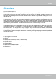
VIVOTEK Physical Description Front Panel Lens IR LED Light Sensor Back Panel Status LED Reset Button Connectors General I/O Terminal Block Ethernet 10/100 RJ45 Plug Power Cord Socket (Black) 4 - User's Manual
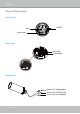
VIVOTEK General I/O Terminal Block This Network Camera provides a general I/O terminal block which is used to connect external input / output devices. The pin definitions are described below. AC24V AC24V DI GND AC24V: 24V+ AC24V: 24VDI : Digital Input GND : Ground Hardware Reset Status LED Reset Button The reset button is used to reset the system or restore the factory default settings. Sometimes resetting the system can return the camera to normal operation.
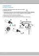
VIVOTEK Installation Hardware Installation 1. Loose the waterproof connector, then remove the rubber. 2. Loose the back cover. 3. Tear down the aluminum foil vacuum bag and take out the moisture absorber. Attach the supplied moisture absorber to the inner side of the Network Camera. (Please replace the moisture absorber with a new one if you open the back cover after installation.) 4. Make sure all cable lines are securely connected. 5. Tighten the back cover, rubber and waterproof connector. 6.
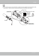
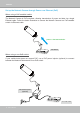
VIVOTEK NOTE ► If you want to use your own cable lines, please loose two supplied screws and take out the power board. Then be careful to make connections as the illustration shown below.
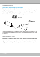
VIVOTEK Network Deployment Setting up the Network Camera over the Internet This section explains how to configure the Network Camera to an Internet connection. 1. If you have external devices such as sensors and alarms, make connections from the general I/O terminal block. 2. Use the supplied RJ45 female/female coupler to connect the Network Camera to a switch. Use a Category 5 Cross Cable when Network Camera is directly connected to PC. 3. Connect the power cable from the Network Camera to a power outlet.
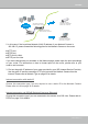
VIVOTEK WAN (Wide Area Network ) Internet Router IP address : from ISP POWER COLLISION 1 2 3 4 5 IP address : 192.168.0.3 Subnet mask : 255.255.255.0 Default router : 192.168.0.1 LINK RECEIVE PARTITION LAN (Local Area Network) Router IP address : 192.168.0.1 Cable or DSL Modem IP address : 192.168.0.2 Subnet mask : 255.255.255.0 Default router : 192.168.0.1 2. In this case, if the Local Area Network (LAN) IP address of your Network Camera is 192.168.0.
VIVOTEK Set up the Network Camera through Power over Ethernet (PoE) When using a PoE-enabled switch The Network Camera is PoE-compliant, allowing transmission of power and data via a single Ethernet cable. Follow the below illustration to connect the Network Camera to a PoE-enabled switch via Ethernet cable.
VIVOTEK Software Installation Installation Wizard 2 (IW2), free-bundled software included on the product CD, helps you set up your Network Camera on the LAN. 1. Install IW2 under the Software Utility directory from the software CD. Double click the IW2 shortcut on your desktop to launch the program. 2. The program will conduct an analysis of your network environment. After your network environment is analyzed, please click Next to continue the program. 3.
VIVOTEK Ready to Use 1. Access the Network Camera on the LAN. 2. Retrieve live video through a web browser or recording software.
VIVOTEK Accessing the Network Camera This chapter explains how to access the Network Camera through web browsers, RTSP players, 3GPP-compatible mobile devices, and VIVOTEK recording software. Using Web Browsers Use Installation Wizard 2 (IW2) to access to the Network Cameras on the LAN. If your network environment is not a LAN, follow these steps to access the Network Camera: 1. Launch your web browser (ex. Microsoft® Internet Explorer, Mozilla Firefox, or Netscape). 2.
VIVOTEK ► By default, the Network Camera is not password-protected. To prevent unauthorized access, it is highly recommended to set a password for the Network Camera. For more information about how to enable password protection, please refer to Security on page 26. ► If you see a dialog box indicating that your security settings prohibit running ActiveX ® Controls, please enable the ActiveX ® Controls for your browser. 1. Choose Tools > Internet Options > Security > Custom Level. 2.
VIVOTEK Using RTSP Players To view the MPEG-4 streaming media using RTSP players, you can use one of the following players that support RTSP streaming. Quick Time Player Real Player VLC media player 1. Launch the RTSP player. mpegable Player 2. Choose File > Open URL. A URL dialog box will pop up. 3.
VIVOTEK Using 3GPP-compatible Mobile Devices To view the streaming media through 3GPP-compatible mobile devices, make sure the Network Camera can be accessed over the Internet. For more information on how to set up the Network Camera over the Internet, please refer to Setup the Network Camera over the Internet on page 8. To utilize this feature, please check the following settings on your Network Camera: 1.
VIVOTEK Using VIVOTEK Recording Software The product software CD also contains recording software, allowing simultaneous monitoring and video recording for multiple Network Cameras. Please install the recording software; then launch the program to add the Network Camera to the Channel list. For detailed information about how to use the recording software, please refer to the user’s manual of the software or download it from http://www.vivotek.com.
VIVOTEK Main Page This chapter explains the layout of the main page. It is composed of the following sections: VIVOTEK INC. Logo, Host Name, Camera Control Area, Configuration Area, Menu, and Live Video Window. VIVOTEK INC. Logo Host Name Camera Control Area Configuration Area Live View Window VIVOTEK INC. Logo Click this logo to visit the VIVOTEK website. Host Name The host name can be customized to fit your needs. For more information, please refer to System on page 24.
VIVOTEK Live Video Window ■ The following window is displayed when the video mode is set to H.264 / MPEG-4: MPEG-4 Protocol and Media Options Video Title Title and Time 2011/05/13 13:44:17 Time Video 13:44:17 2011/05/13 Video Control Buttons Video Title: The video title can be configured. For more information, please refer to Video Settings on page 51. H.264 / MPEG-4 Protocol and Media Options: The transmission protocol and media options for H.264 / MPEG-4 video streaming.
VIVOTEK Full Screen: Click this button to switch to full screen mode. Press the “Esc” key to switch back to normal mode. ■ The following window is displayed when the video mode is set to MJPEG: Video Title Title and Time 2011/05/13 13:44:17 Time Video 13:44:17 2011/05/13 Video Control Buttons Video Title: The video title can be configured. For more information, please refer to Video Settings on page 51. Time: Display the current time. For more information, please refer to Video Settings on page 51.
VIVOTEK Client Settings This chapter explains how to select the stream transmission mode and saving options on the local computer. When completed with the settings on this page, click Save on the page bottom to enable the settings. H.264 / MPEG-4 Protocol Options H.264/MPEG-4 Protocol Options Depending on your network environment, there are four transmission modes of H.264 or MPEG-4 streaming: UDP unicast: This protocol allows for more real-time audio and video streams.
VIVOTEK MP4 Saving Options Users can record live video as they are watching it by clicking page. Here, you can specify the storage destination and file name. Start MP4 Recording on the main Folder: Specify a storage destination for the recorded video files. File name prefix: Enter the text that will be appended to the front of the video file name. Add date and time suffix to the file name: Select this option to append the date and time to the end of the file name.
VIVOTEK Configuration Click Configuration on the main page to enter the camera setting pages. Note that only Administrators can access the configuration page. VIVOTEK offers an easy-to-use user interface that helps you set up your network camera with minimal effort. To simplify the setting procedure, two types of user interfaces are available: Advanced Mode for professional users and Basic Mode for entry-level users.
VIVOTEK Advanced Mode Configuration List Click to switch to Basic Mode Firmware Version Each function on the configuration list will be explained in the following sections. Those functions that are displayed only in Advanced Mode are marked with Advanced Mode . If you want to set up advanced functions, please click [Advanced Mode] on the bottom of the configuration list to quickly switch over.
VIVOTEK System Time Keep current date and time: Select this option to preserve the current date and time of the Network Camera. The Network Camera’s internal real-time clock maintains the date and time even when the power of the system is turned off. Synchronize with computer time: Select this option to synchronize the date and time of the Network Camera with the local computer. The read-only date and time of the PC is displayed as updated. Manual: The administrator can enter the date and time manually.
VIVOTEK Security This section explains how to enable password protection and create multiple accounts. Root Password The administrator account name is “root”, which is permanent and can not be deleted. If you want to add more accounts in the Manage User column, please apply the password for the “root” account first. 1. Type the password identically in both text boxes, then click Save to enable password protection. 2.
VIVOTEK HTTPS (Hypertext Transfer Protocol over SSL) Advanced Mode This section explains how to enable authentication and encrypted communication over SSL (Secure Socket Layer). It helps protect streaming data transmission over the Internet on higher security level. Enable HTTPS Check this item to enable HTTPS communication, then select a connection option: "HTTP & HTTPS" or "HTTPS only". Note that you have to create and install a certificate first in the second column before clicking the Save button.
VIVOTEK 4. The Certificate Information will automatically be displayed in the third column as shown below. You can click Property to view detailed information about the certificate. 5. Click Home to return to the main page. Change the address from “http://” to “https://“ in the address bar and press Enter on your keyboard. Some Security Alert dialogs will pop up. Click OK or Yes to enable HTTPS. https:// https://192.168.5.151/index.
VIVOTEK Create self-signed certificate manually 1. Select this option. 2. Click Create to open the Create Certificate page, then click Save to generate the certificate. 3. The Certificate Information will automatically be displayed in the third column as shown below. You can click Property to see detailed information about the certificate. Create certificate and install : Select this option if you want to create a certificate from a certificate authority. 1. Select this option. 2.
VIVOTEK 3. If you see the following Information bar, click OK and click on the Information bar at the top of the page to allow pop-ups. 4. The pop-up window shows an example of a certificate request.
VIVOTEK 5. Look for a trusted certificate authority that issues digital certificates. Enroll the Network Camera. Wait for the certificate authority to issue a SSL certificate; click Browse... to search for the issued certificate, then click Upload in the second column. NOTE ► How do I cancel the HTTPS settings? 1. Uncheck Enable HTTPS secure connection in the first column and click Save; a warning dialog will pop up. 2. Click OK to disable HTTPS. 3.
VIVOTEK Network This section explains how to configure a wired network connection for the Network Camera. Network Type LAN Select this option when the Network Camera is deployed on a local area network (LAN) and is intended to be accessed by local computers. The default setting for the Network Type is LAN. Rememer to click Save when you complete the Network setting.
VIVOTEK Primary DNS: The primary domain name server that translates hostnames into IP addresses. Secondary DNS: Secondary domain name server that backups the Primary DNS. Primary WINS server: The primary WINS server that maintains the database of computer name and IP address. Secondary WINS server: The secondary WINS server that maintains the database of computer name and IP address.
VIVOTEK NOTE ► If the default ports are already used by other devices connected to the same router, the Network Camera will select other ports for the Network Camera. ► If UPnP TM is not supported by your router, you will see the following message: Error: Router does not support UPnP port forwarding. ► Steps to enable the UPnP TM user interface on your computer: Note that you must log on to the computer as a system administrator to install the UPnP TM components. 1.
VIVOTEK 4. In the Networking Services dialog box, select Universal Plug and Play and click OK. 5. Click Next in the following window. 6. Click Finish. UPnP TM is enabled. ► How does UPnP TM work? UPnP TM networking technology provides automatic IP configuration and dynamic discovery of devices added to a network. Services and capabilities offered by networked devices, such as printing and file sharing, are available among each other without the need for cumbersome network configuration.
VIVOTEK Enable IPv6 Select this option and click Save to enable IPv6 settings. Please note that this only works if your network environment and hardware equipment support IPv6. The browser should be Microsoft® Internet Explorer 6.5, Mozilla Firefox 3.0 or above. When IPv6 is enabled, by default, the network camera will listen to router advertisements and be assigned with a link-local IPv6 address accordingly. IPv6 Information: Click this button to obtain the IPv6 information as shown below.
VIVOTEK Please follow the steps below to link to an IPv6 address: 1. Open your web browser. 2. Enter the link-global or link-local IPv6 address in the address bar of your web browser. 3. The format should be: http://[2001:0c08:2500:0002:0202:d1ff:fe04:65f4]/ IPv6 address 4. Press Enter on the keyboard or click Refresh button to refresh the webpage.
VIVOTEK IEEE 802.1x Advanced Mode Enable this function if your network environment uses IEEE 802.1x, which is a port-based network access control. The network devices, intermediary switch/access point/hub, and RADIUS server must support and enable 802.1x settings. The 802.1x standard is designed to enhance the security of local area networks, which provides authentication to network devices (clients) attached to a network port (wired or wireless).
VIVOTEK 3. When all settings are complete, move the Network Camera to the protected LAN by connecting it to an 802.1x enabled switch. The devices will then start the authentication automatically. NOTE ► The authentication process for 802.1x: 1. The Certificate Authority (CA) provides the required signed certificates to the Network Camera (the supplicant) and the RADIUS Server (the authentication server). 2. A Network Camera requests access to the protected LAN using 802.
VIVOTEK QoS (Quality of Service) Advanced Mode Quality of Service refers to a resource reservation control mechanism, which guarantees a certain quality to different services on the network. Quality of service guarantees are important if the network capacity is insufficient, especially for real-time streaming multimedia applications. Quality can be defined as, for instance, a maintained level of bit rate, low latency, no packet dropping, etc.
VIVOTEK QoS/DSCP (the DiffServ model) DSCP-ECN defines QoS at Layer 3 (Network Layer). The Differentiated Services (DiffServ) model is based on packet marking and router queuing disciplines. The marking is done by adding a field to the IP header, called the DSCP (Differentiated Services Codepoint). This is a 6-bit field that provides 64 different class IDs. It gives an indication of how a given packet is to be forwarded, known as the Per Hop Behavior (PHB).
VIVOTEK HTTP Advanced Mode To utilize HTTP authentication, make sure that your have set a password for the Network Camera first; please refer to Security on page 26 for details. Authentication: Depending on your network security requirements, the Network Camera provides two types of security settings for an HTTP transaction: basic and digest. If basic authentication is selected, the password is sent in plain text format and there can be potential risks of being intercepted.
VIVOTEK URL command -- http://:/ For example, when the Access name for stream 2 is set to video2.mjpg: 1. Launch Mozilla Firefox or Netscape. 2. Type the above URL command in the address bar. Press Enter. 3. The JPEG images will be displayed in your web browser. http://192.168.5.151/video2.
VIVOTEK RTSP Streaming To utilize RTSP streaming authentication, make sure that you have set a password for the Network Camera first; please refer to Security on page 26 for details. Authentication: Depending on your network security requirements, the Network Camera provides three types of security settings for streaming via RTSP protocol: disable, basic, and digest. If basic authentication is selected, the password is sent in plain text format, but there can be potential risks of it being intercepted.
VIVOTEK RTSP port /RTP port for video/ RTCP port for video ■ RTSP (Real-Time Streaming Protocol) controls the delivery of streaming media. By default, the port number is set to 554. ■ The RTP (Real-time Transport Protocol) is used to deliver video data to the clients. By default, the RTP port for video is set to 5556. ■ The RTCP (Real-time Transport Control Protocol) allows the Network Camera to transmit the data by monitoring the Internet traffic volume. By default, the RTCP port for video is set to 5557.
VIVOTEK DDNS This section explains how to configure the dynamic domain name service for the Network Camera. DDNS is a service that allows your Network Camera, especially when assigned with a dynamic IP address, to have a fixed host and domain name. DDNS: Dynamic domain name service Enable DDNS: Select this option to enable the DDNS setting. Provider: Select a DDNS provider from the provider drop-down list. VIVOTEK offers Safe100.net, a free dynamic domain name service, to VIVOTEK customers.
VIVOTEK [Register] Successfully Your account information has been mailed to registered e-mail address 4. Select Enable DDNS and click Save to enable the setting. ■ CustomSafe100 VIVOTEK offers documents to establish a CustomSafe100 DDNS server for distributors and system integrators. You can use CustomSafe100 to register a dynamic domain name if your distributor or system integrators offer such services. 1. In the DDNS column, select CustomSafe100 from the drop-down list. 2.
VIVOTEK Access List Advanced Mode This section explains how to control access permission by verifying the client PC’s IP address. General Settings Maximum number of concurrent streaming connection(s) limited to: Simultaneous live viewing for 1~10 clients (including stream 1 ~ stream 5). The default value is 10. If you modify the value and click Save, all current connections will be disconnected and automatically attempt to re-link (IE Explore or Quick Time Player).
VIVOTEK ■ Refresh: Click this button to refresh all current connections. ■ Add to deny list: You can select entries from the Connection Status list and add them to the Deny List to deny access. Please note that those checked connections will only be disconnected temporarily and will automatically try to re-link again (IE Explore or Quick Time Player). If you want to enable the denied list, please check Enable access list filtering and click Save in the first column.
VIVOTEK Network: This rule allows the user to assign a network address and corresponding subnet mask to the Allow/Deny List. For example: IP address 192.168.2.x will be blocked. Range: This rule allows the user to assign a range of IP addresses to the Allow/Deny List. Note: This rule is only applied to IPv4.
VIVOTEK Video This section explains how to configure the video settings of the Network Camera. Video Settings Video title: Enter a name that will be displayed on the title bar of the live video. Video Title Title and Time 2011/05/13 13:44:17 Video 13:44:17 2011/05/13 Color: Select to display color or black/white video streams. Power line frequency: Set the power line frequency consistent with local utility settings to eliminate image flickering associated with fluorescent lights.
VIVOTEK 2011/05/13 13:44:17 13:44:17 2011/05/13 Indoor Mode: To prevent color rolling effect under fluorescent light, please check this item to adjust the parameter. Image Settings Advanced Mode Click Image Settings to open the Image Settings page. On this page, you can tune the White balance, Brightness, Saturation, Contrast, and Sharpness settings for the video.
VIVOTEK White balance: Adjust the value for the best color temperature. ■ Auto The Network Camera automatically adjusts the color temperature of the light in response to different light sources. The white balance setting defaults to Auto and works well in most situations. ■ Keep current value Follow the steps below to manually set the white balance to compensate for the ambient lighting conditions. 1. Set the White balance to Auto and click Save. 2.
VIVOTEK Video Quality Settings Advanced Mode Click the stream item to display the detailed information. This Network Camera offers real-time H.264, MPEG-4 and MJEPG compression standards (Triple Codec) for real-time viewing. If H.264 / MPEG-4 mode is selected, the video is streamed via RTSP protocol. There are four parameters for you to adjust the video performance: ■ Frame size You can set up different video resolution for different viewing devices.
VIVOTEK ■ Intra frame period Determine how often to plant an I frame. The shorter the duration, the more likely you will get better video quality, but at the cost of higher network bandwidth consumption. Select the intra frame period from the following durations: 1/4 second, 1/2 second, 1 second, 2 seconds, 3 seconds, and 4 seconds. ■ Video quality A complex scene generally produces a larger file size, meaning that higher bandwidth will be needed for data transmission.
VIVOTEK Day/Night Settings Switch to B/W in night mode Select this to enable the Network Camera to automatically switch to B/W during night mode. IR LED With built-in IR illuminators, up to 15m, this Network Camera can make use of IR light during low light conditions. ■ Auto mode The Network Camera automatically control the IR LED by judging the level of ambient light. ■ Day mode Select “Day mode” to turn on the IR LED. ■ Night mode Select “Night mode” to turn off the IR LED.
VIVOTEK Motion Detection This section explains how to configure the Network Camera to enable motion detection. A total of three motion detection windows can be configured. 2011/05/13 13:44:17 Motion Detection Setting 1: For normal situations Follow the steps below to enable motion detection: Follow the steps below to enable motion detection: Motion Detection Setting 2: For special situations 1. Click New to add a new motion detection window. 2.
VIVOTEK A green bar indicates that even though motions have been detected, the event has not been triggered because the image variations still fall under the defined threshold. Percentage = 30% If you want to configure other motion detection settings for day/night/schedule mode, please click Profile to open the Motion Detection Profile Settings page as shown below. A total of three motion detection windows can be configured on this page as well.
VIVOTEK NOTE ► How does motion detection work? A C B D There are two motion detection parameters: Sensitivity and Percentage. In the illustration above, frame A and frame B are two sequential images. Pixel differences between the two frames are detected and highlighted in gray (frame C) and will be compared with the sensitivity setting. Sensitivity is a value that expresses the sensitivity to moving objects.
VIVOTEK Camera Tampering Detection This section explains how to set up camera tamper detection. With tamper detection, the camera is capable of detecting incidents such as redirection, blocking or defocusing, or even spray paint. Please follow the steps below to set up the camera tamper detection function: 1. Check Enable camera tampering detection. 2. Enter the tamper trigger duration. (10 sec. ~ 10 min.
VIVOTEK Homepage Layout Advanced Mode This section explains how to set up your own customized homepage layout. Preview This column shows the settings of your hompage layout. You can manually select the background and font colors in Theme Options (the third column on this page). The settings will be displayed automatically in this Preview field. The following shows the homepage using the default settings: ■ Hide Powered by VIVOTEK: If you check this item, it will be removed from the homepage.
VIVOTEK Theme Options Here you can change the color of your homepage layout. There are three types of preset patterns for you to choose from. The new layout will simultaneously appear in the Preview filed. Click Save to enable the settings.
VIVOTEK ■ Follow the steps below to set up the customed homepage: 1. Click Custom on the left column. 2. Click the field where you want to change the color on the right column. Color Selector Custom Pattern 3. The palette window will pop up as shown below. 2 3 1 4 4. Drag the slider bar and click on the left square to select a desired color. 5. The selected color will be displayed in the corresponding fields and in the Preview column. 6. Click Save to enable the settings.
VIVOTEK Application Advanced Mode This section explains how to configure the Network Camera to responds to particular situations (event). A typical application is that when a motion is detected, the Network Camera sends buffered images to an FTP server or e-mail address as notifications. In the illustration on the right, an event can be triggered by many sources, such as motion detection Event Trigger Action or external digital input devices. When an event is ex.
VIVOTEK Event Settings In the Event Settings column, click Add to open the Event Settings page. On this page, you can arrange three elements -- Trigger, Schedule, and Action to set an event. A total of 3 event settings can be configured. Event name: Enter a name for the event setting. Enable this event: Select this option to enable the event setting. Priority: Select the relative importance of this event (High, Normal, or Low). Events with a higher priority setting will be executed first.
VIVOTEK An event is an action initiated by a user-defined trigger source; it is the causal arrangement of the following three elements: Trigger, Event Schedule, and Action. Trigger This is the cause or stimulus which defines when to trigger the Network Camera. The trigger source can be configured to use the Network Camera’s built-in motion detection mechanism or external digital input devices. There are several choices of trigger sources as shown below.
VIVOTEK ■ Manual Trigger This option allows user to enable event triggers manually by clicking the on/off button on the homepage. Please configure 1 ~ 3 events before using this function. Event Schedule Specify the period for the event. ■ Select the days of the week. ■ Select the recording schedule in 24-hr time format. Action Define the actions to be performed by the Network Camera when a trigger is activated.
VIVOTEK Here is an example of the Event Settings page: When completed, click Save to enable the settings and click Close to exit Event Settings page. The new event settings / server settings / media settings will appear in the event drop-down list on the Application page.
VIVOTEK Here is an example of the Application page with an event setting: When the Event Status is ON, once an event is triggered by motion detection, the Network Camera will automatically send snapshots via e-mail. If you want to stop the event trigger, you can click ON to turn it to OFF status or click Delete to remove the event setting. To remove a server setting from the list, select a server name from the drop-down list and click Delete.
VIVOTEK Server Settings Click Add Server on Event Settings page to open the Server Setting page. On this page, you can specify where the notification messages are sent when a trigger is activated. A total of 5 server settings can be configured. Server name: Enter a name for the server setting. Server Type There are four choices of server types available: Email, FTP, HTTP, and Network storage. Select the item to display the detailed configuration options. You can configure either one or all of them.
VIVOTEK FTP: Select to send the media files to an FTP server when a trigger is activated. ■ Server address: Enter the domain name or IP address of the FTP server. ■ Server port By default, the FTP server port is set to 21. It can also be assigned to another port number between 1025 and 65535. ■ User name: Enter the login name of the FTP account. ■ Password: Enter the password of the FTP account. ■ FTP folder name Enter the folder where the media file will be placed.
VIVOTEK HTTP: Select to send the media files to an HTTP server when a trigger is activated. ■ URL: Enter the URL of the HTTP server. ■ User name: Enter the user name if necessary. ■ Password: Enter the password if necessary. To verify if the HTTP settings are correctly configured, click Test. The result will be shown in a pop-up window as below. If successful, you will receive a test.txt file on the HTTP server. Click Save to enable the settings, then click Close to exit the page.
VIVOTEK Media Settings Click Add Media on the Event Settings page to open the Media Settings page. On this page, you can specify the type of media that will be sent when a trigger is activated. A total of 5 media settings can be configured. Media name: Enter a name for the media setting. Media Type There are three choices of media types available: Snapshot, Video Clip, and System log. Select the item to display the detailed configuration options. You can configure either one or all of them.
VIVOTEK Video clip: Select to send video clips when a trigger is activated. ■ Source: Select a source of video clip. ■ Pre-event recording The Network Camera has a buffer area; it temporarily holds data up to a certain limit. Enter a number to decide the duration of recording before a trigger is activated. Up to 9 seconds can be set. ■ Maximum duration Specify the maximum recording duration in seconds. Up to 10 seconds can be set.
VIVOTEK You can continue to select a server and media type for the event. Please go back to page 66 for detailed information. ■ Create folders by date, time, and hour automatically: If you check this item, the system will generate folders automatically by date. ■ View: Click this button to open a file list window. This function is only for Network Storage. If you click View button of Network storage, a file directory window will pop up for you to view recorded data on Network storage.
VIVOTEK The following is an example of a file destination with video clips: The format is: YYYYMMDD Click to open the directory 20110515 20110516 20110517 Click to delete all recorded data Click to delete selected items Click 20110515 to open the directory: The format is: HH (24r) Click to open the file list for that hour Video Clip_58.mp4 2011/05/15 Video Clip_59.
VIVOTEK Recording Advanced Mode This section explains how to configure the recording settings for the Network Camera. Recording Settings NOTE ► Before setting up this page, please set up the Network Storage on the Server Settings page first. Network Storage Setting Click Server to open the Server Settings page and follow the steps below to set up: 1. Fill in the information for your server.
VIVOTEK If successful, you will receive a test.txt file on the network storage server. 3. Enter a server name. 4. Click Save to complete the settings and click Close to exit the page. Recording Settings Click Add to open the recording setting page. In this page, you can define the recording source, recording schedule, and recording capacity. A total of 2 recording settings can be configured.
VIVOTEK Recording name: Enter a name for the recording setting. Enable this recording: Select this option to enable video recording. With adaptive recording: Select this option will activate the frame rate control according to alarm trigger. The frame rate control means that when there is alarm trigger, the frame rate will raise up to the value you’ve set on Video quality setting page. Please refer to page 54 for more information.
VIVOTEK When completed, select Enable this recording. Click Save to enable the setting and click Close to exit this page. When the system begins recording, it will send the recorded files to the Network Storage. The new recording name will appear in the drop-down list on the recording page as shown below. To remove a recording setting from the list, select a recording name from the drop-down list and click Delete. ■ Click Video (Name): Opens the Recording Settings page to modify.
VIVOTEK System Log Advanced Mode This section explains how to configure the Network Camera to send the system log to the remote server as backup. Remote Log You can configure the Network Camera to send the system log file to a remote server as a log backup. Before utilizing this feature, it is suggested that the user install a log-recording tool to receive system log messages from the Network Camera. An example is Kiwi Syslog Daemon. Visit http://www.kiwisyslog. com/kiwi-syslog-daemon-overview/.
VIVOTEK View Parameters Advanced Mode The View Parameters page lists the entire system’s parameters in alphabetical order. If you need technical assistance, please provide the information listed on this page.
VIVOTEK Maintenance This chapter explains how to restore the Network Camera to factory default, upgrade firmware version, etc. Reboot This feature allows you to reboot the Network Camera, which takes about one minute to complete. When completed, the live video page will be displayed in your browser. The following message will be displayed during the reboot process. If the connection fails after rebooting, manually enter the IP address of the Network Camera in the address field to resume the connection.
VIVOTEK Export / Upload Files Advanced Mode This feature allows you to Export / Upload daylight saving time rules, custom language files, and setting backup files. Export daylight saving time configuration file: Click to set the start and end time of DST. Follow the steps below to export: 1. In the Export files column, click Export to export the daylight saving time configuration file from the Network Camera. 2. A file download dialog will pop up as shown below.
VIVOTEK Upload daylight saving time rule: Click Browse… and specify the XML file to upload. If the incorrect date and time are assigned, you will see the following warning message when uploading the file to the Network Camera. The following message is displayed when attempting to upload an incorrect file format. Export language file: Click to export language strings. VIVOTEK provides nine languages: English, Deutsch, Español, Français, Italiano, 日本語 , Português, 簡体中文 , and 繁體中文 .
VIVOTEK The following message is displayed when the upgrade has succeeded. Reboot system now!! This connection will close. The following message is displayed when you have selected an incorrect firmware file. Starting firmware upgrade... Do not power down the server during the upgrade. The server will restart automatically after the upgrade is completed. This will take about 1 - 5 minutes.
VIVOTEK Appendix URL Commands for the Network Camera Overview For some customers who already have their own web site or web control application, the Network Camera/Video Server can be easily integrated through URL syntax. This section specifies the external HTTP-based application programming interface. The HTTP-based camera interface provides the functionality to request a single image, control camera functions (PTZ, output relay etc.), and get and set internal parameter values.
VIVOTEK 3. General CGI URL Syntax and Parameters CGI parameters are written in lower-case and as one word without any underscores or other separators. When the CGI request includes internal camera parameters, these parameters must be written exactly as they are named in the camera or video server. The CGIs are organized in functionally-related directories under the cgi-bin directory. The file extension .cgi is required. Syntax: http:///cgi-bin/[/...]/.
VIVOTEK http:///cgi-bin/viewer/getparam.cgi?[] [&…] http:///cgi-bin/operator/getparam.cgi?[] [&…] http:///cgi-bin/admin/getparam.cgi?[] [&…] Where the should be [_] or [.]. If you do not specify any parameters, all the parameters on the server will be returned. If you specify only , the parameters of the related group will be returned.
VIVOTEK 6. Set Server Parameter Values Note: The access right depends on the URL directory. Method: GET/POST Syntax: http:///cgi-bin/anonymous/setparam.cgi? = [&=…][&update=][&return=] http:///cgi-bin/viewer/setparam.cgi? = [&=…][&update=] [&return=] http:///cgi-bin/operator/setparam.
VIVOTEK =\r\n [] Only the parameters that you set and are readable will be returned. Example: Set the IP address of server to 192.168.0.123: Request: http://myserver/cgi-bin/admin/setparam.cgi?network_ipaddress=192.168.0.123 Response: HTTP/1.0 200 OK\r\n Content-Type: text/html\r\n Context-Length: 33\r\n \r\n network.ipaddress=192.168.0.123\r\n 7.
VIVOTEK integer primary key SQLite data type. A 32-bit signed integer. The value is assigned a unique integer by the server. text SQLite data type. The value is a text string, stored using the database encoding (UTF-8, UTF-16BE or UTF-16-LE). coordinate x, y coordinate (eg. 0,0) window size window width and height (eg. 800x600) NOTE: The camera should not be restarted when parameters are changed. 7.
VIVOTEK -240: GMT-06:00 Central America, Central Time, Mexico City, Saskatchewan -200: GMT-05:00 Eastern Time, New York, Toronto -201: GMT-05:00 Bogota, Lima, Quito, Indiana -180: GMT-04:30 Caracas -160: GMT-04:00 Atlantic Time, Canada, La Paz, Santiago -140: GMT-03:30 Newfoundland -120: GMT-03:00 Brasilia, Buenos Aires, Georgetown, Greenland -80: GMT-02:00 Mid-Atlantic -40: GMT-01:00 Azores, Cape_Verde_IS.
VIVOTEK 360: GMT 09:00 Osaka, Sapporo, Tokyo, Seoul, Yakutsk 380: GMT 09:30 Adelaide, Darwin 400: GMT 10:00 Brisbane, Canberra, Melbourne, Sydney, Guam, Vladivostok 440: GMT 11:00 Magadan, Solomon Is., New Caledonia 480: GMT 12:00 Aucklan, Wellington, Fiji, Kamchatka, Marshall Is. 520: GMT 13:00 Nuku'Alofa daylight_enable 6/6 Enable automatic daylight saving time in time zone. daylight_dstact 6/7 Check if current time is under daylight saving time.
VIVOTEK “restoreexceptXYZ” commands. When cooperating with others, the system parameters will be restored to default values except for a union of combined results. restoreexceptla 7/6 Restore the system parameters to default values ng except the custom language file the user has uploaded. This command can cooperate with other “restoreexceptXYZ” commands. When cooperating with others, the system parameters will be restored to the default value except for a union of the combined results. 7.
VIVOTEK 7.2 status Group: status NAME VALUE SECURITY DESCRIPTION (get/set) di_i<0~(ndi-1)> 1/7 0 => Inactive, normal 1 => Active, triggered daynight day, night 7/7 Current status of day, night. onlinenum_rtsp integer 6/7 Current number of RTSP connections. onlinenum_httppush integer 6/7 Current number of HTTP push server connections. vi_i<0~(nvi-1)> 1/7 Virtual input 0 => Inactive 1 => Active 7.3 digital input behavior define Group: di_i<0~(ndi-1)> (capability.
VIVOTEK 7.5 network Group: network NAME VALUE SECURITY DESCRIPTION (get/set) preproces 7/6 An 32-bit integer, each bit can be set separately as follows: Bit 0 => HTTP service; Bit 1=> HTTPS service; Bit 2=> FTP service; Bit 3 => Two way audio and RTSP Streaming service; To stop service before changing its port settings. It’s recommended to set this parameter when change a service port to the port occupied by another service currently. Otherwise, the service may fail.
VIVOTEK 7.5.1 802.1x Subgroup of network: ieee8021x NAME VALUE SECURITY DESCRIPTION (get/set) enable 6/6 Enable/disable IEEE 802.1x eapmethod eap-peap, eap-tls 6/6 Selected EAP method identity_peap String[64] 6/6 PEAP identity identity_tls String[64] 6/6 TLS identity password String[254] 6/6 Password for TLS privatekeypassword String[254] 6/6 Password for PEAP ca_exist 6/6 CA installed flag ca_time 6/7 CA installed time.
VIVOTEK Subgroup of network: qos_dscp NAME VALUE SECURITY DESCRIPTION (get/set) enable 6/6 Enable/disable DSCP video 0~63 6/6 Video channel for DSCP audio 0~63 6/6 Audio channel for DSCP (capability.naudio > 0) eventalarm 0~63 6/6 Event/alarm channel for DSCP management 0~63 6/6 Management channel for DSCP eventtunnel 0~63 6/6 Event/Control channel for DSCP 7.5.
VIVOTEK s0_accessname string[32] 1/6 HTTP server push access name for stream 1. s1_accessname string[32] 1/6 HTTP server push access name for stream 2. anonymousviewing 1/6 Enable anoymous streaming viewing. 7.5.6 HTTPS port Subgroup of network: https_port NAME VALUE SECURITY DESCRIPTION (get/set) port 443, 1025 ~ 65535 1/6 HTTPS port. 7.5.7 RTSP Subgroup of network: rtsp (capability.protocol.
VIVOTEK 7.5.9 RTP port Subgroup of network: rtp NAME VALUE SECURITY DESCRIPTION (get/set) videoport 1025 ~ 65535 6/6 Video channel port for RTP. 7.5.10 PPPoE Subgroup of network: pppoe (capability.protocol.pppoe > 0) NAME VALUE SECURITY DESCRIPTION (get/set) user string[128] 6/6 PPPoE account user name. pass password[64] 6/6 PPPoE account password. 7.6 IP Filter Group: ipfilter NAME VALUE SECURITY DESCRIPTION (get/set) enable 6/6 Enable access list filtering.
VIVOTEK 7.7 Video input Group: videoin NAME VALUE SECURITY DESCRIPTION (get/set) cmosfreq 50, 60 4/4 CMOS frequency. whitebalance auto, manual 4/4 “auto” indicates auto white balance. “manual” indicates keep current value. 7.7.
VIVOTEK s<0~(m-1)>_mpeg4_bitra 1000~4000000 4/4 te Set bit rate in bps when choosing cbr in “ratecontrolmode”. s<0~(m-1)>_mpeg4_max 1~25, frame 26~30 (only for 1/4 Set maximum frame rate in fps (for MPEG-4). NTSC or 60Hz CMOS) s<0~(m-1)>_h264_intrap 250, 500, 1000, eriod 2000, 3000, 4/4 Intra frame period in milliseconds.
VIVOTEK 7.10 Image setting per channel Group: image_c<0~(n-1)> for n channel products NAME VALUE SECURITY DESCRIPTION (get/set) brightness -5~5 4/4 Adjust brightness of image according to mode settings. saturation -5~5 4/4 Adjust saturation of image according to mode settings. contrast -5 ~ 5 4/4 Adjust contrast of image according to mode settings. sharpness -3 ~ 3 4/4 Adjust sharpness of image according to mode settings. 7.
VIVOTEK i<0~(m-1)>_policy day, 4/4 night, The mode which the profile is applied to. schedule i<0~(m-1)>_begintime hh:mm 4/4 Begin time of schedule mode. i<0~(m-1)>_endtime hh:mm 4/4 End time of schedule mode. i<0~(m-1)>_win_i<0~2>_enable 4/4 Enable motion window. i<0~(m-1)>_win_i<0~2>_name string[14] 4/4 Name of motion window. i<0~(m-1)>_win_i<0~2>_left 0 ~ 320 4/4 Left coordinate of window position.
VIVOTEK _ho string[128] 6/6 Your DDNS hostname. string[64] 6/6 Your user name or email to login to the DDNS service stname _us ernameemail _pa provider string[64] 6/6 sswordkey _se Your password or key to login to the DDNS service provider. string[128] 6/6 rvername The server name for safe100. (This field only exists if the provider is customsafe100) 7.
VIVOTEK level 0~7 6/6 Levels used to distinguish the importance of the information: 0: LOG_EMERG 1: LOG_ALERT 2: LOG_CRIT 3: LOG_ERR 4: LOG_WARNING 5: LOG_NOTICE 6: LOG_INFO 7: LOG_DEBUG 7.
VIVOTEK 7.27 Privacy mask Group: privacymask_c<0~(n-1)> for n channel product NAME VALUE SECURITY DESCRIPTION (get/set) enable 4/4 Enable privacy mask. win_i<0~4>_enable 4/4 Enable privacy mask window. win_i<0~4>_name string[14] 4/4 Name of the privacy mask window. win_i<0~4>_left 0 ~ 320/352 4/4 Left coordinate of window position. win_i<0~4>_top 0 ~ 240/288 4/4 Top coordinate of window position. win_i<0~4>_width 0 ~ 320/352 4/4 Width of privacy mask window.
VIVOTEK nvideoinprofile 0/7 Number of video input profiles. nmotionprofile 0, 0/7 Number of motion profiles.
VIVOTEK protocol_maxmegac 0/7 onnection protocol_rtp_multica connections. 0/7 st_scalable protocol_rtp_multica The maximum megapixel streaming Indicate whether to support scalable multicast. 0/7 st_backchannel Indicate whether to support backchannel multicast. protocol_rtp_tcp 0/7 Indicate whether to support RTP over TCP. protocol_rtp_http 0/7 Indicate whether to support RTP over HTTP.
VIVOTEK input. (It will be replaced by audio_mic and audio_extmic.) audio_lineout 0/7 Indicate whether to support line output. audio_headphoneout 0/7 Indicate whether to support headphone output. audioin_codec aac4, gamr, g711 0/7 Available codec list for audio input. 0/7 Available codec list for SIP. audioout_codec g711 camctrl_httptunnel 0/7 Indicate whether to support httptunnel.
VIVOTEK wireless_endchannel 1 ~ 14 0/7 Indicate the end channel of wireless network derivative_brand 0/7 Indicate whether to support the upgrade function for the derivative brand. For example, if the value is true, the VVTK product can be upgraded to VVXX. (TCVV<->TCXX is excepted) npreset 0, 0/7 Number of preset locations eptz 0, 0/7 A 32-bit integer, each bit can be set separately as follows: Bit 0 => stream 1 supports ePTZ or not.
VIVOTEK priority 0, 1, 2 6/6 Indicate the priority of this event: “0” = low priority “1” = normal priority “2” = high priority delay 1~999 6/6 Delay in seconds before detecting the next event. trigger boot, 6/6 Indicate the trigger condition: di, “boot” = System boot motion, “di”= Digital input seq, “motion” = Video motion detection recnotify, “seq” = Periodic condition tampering, “recnotify” = Recording notification. vi “tampering” = Tamper detection.
VIVOTEK weekday 0~127 6/6 Indicate which weekday is scheduled. One bit represents one weekday. bit0 (LSB) = Saturday bit1 = Friday bit2 = Thursday bit3 = Wednesday bit4 = Tuesday bit5 = Monday bit6 = Sunday For example, to detect events on Friday and Sunday, set weekday as 66. begintime hh:mm 6/6 Begin time of the weekly schedule. endtime hh:mm 6/6 End time of the weekly schedule. (00:00 ~ 24:00 sets schedule as always on) action_server_i<0~4>_e 0, 1 6/6 Enable or disable this server action.
VIVOTEK ftp_location string[128] 6/6 Location to upload or store the media. ftp_passive 0, 1 6/6 Enable or disable passive mode. 0 = disable passive mode 1 = enable passive mode email_address string[128] 6/6 Email server address. email_sslmode 0, 1 6/6 Enable support SSL. email_port 0~65535 6/6 Port to connect to the server. email_username string[64] 6/6 Username to log in to the server. email_passwd string[64] 6/6 Password of the user.
VIVOTEK videoclip_preevent 0~9 6/6 Indicates the time for pre-event recording in seconds. videoclip_maxduration 1 ~ 10 6/6 Maximum duration of one video clip in seconds. videoclip_maxsize 50 ~ 1024 6/6 Maximum size of one video clip file in Kbytes. 7.33 Recording Group: recording_i<0~1> PARAMETER VALUE SECURITY DESCRIPTION (get/set) name string[40] 6/6 Identification of this entry. enable 0, 1 6/6 Enable or disable this recording.
VIVOTEK weekday 0~127 6/6 Indicate which weekday is scheduled. One bit represents one weekday. bit0 (LSB) = Saturday bit1 = Friday bit2 = Thursday bit3 = Wednesday bit4 = Tuesday bit5 = Monday bit6 = Sunday For example, to detect events on Friday and Sunday, set weekday as 66. begintime hh:mm 6/6 Start time of the weekly schedule. endtime hh:mm 6/6 End time of the weekly schedule. (00:00~24:00 indicates schedule always on) prefix string[16] 6/6 Indicate the prefix of the filename.
VIVOTEK status -3 ~ 1 6/7 Specify the https status. -3 = Certificate not installed -2 = Invalid public key -1 = Waiting for certificate 0 = Not installed 1 = Active countryname string[2] 6/6 Country name in the certificate information. stateorprovincename string[128] 6/6 State or province name in the certificate information. localityname string[128] 6/6 The locality name in the certificate information. organizationname string[64] 6/6 Organization name in the certificate information.
VIVOTEK 8. Useful Functions 8.1 Query Status of the Digital Input Note: This request requires Viewer privileges Method: GET/POST Syntax: http:///cgi-bin/dido/getdi.cgi?[di0] If no parameter is specified, all of the digital input statuses will be returned. Return: HTTP/1.0 200 OK\r\n Content-Type: text/plain\r\n Content-Length: \r\n \r\n [di0=]\r\n where can be 0 or 1. Example: Query the status of digital input 1. Request: http://myserver/cgi-bin/dido/getdi.
VIVOTEK If the user requests a size larger than all stream settings on the server, this request will fail. PARAMETER VALUE DEFAULT DESCRIPTION channel 0~(n-1) 0 The channel number of the video source. resolution 0 The resolution of the image. quality 1~5 3 The quality of the image. streamid 0~(m-1) The stream number. The server will return the most up-to-date snapshot of the selected channel and stream in JPEG format.
VIVOTEK Return viewer Viewer privilege. operator Operator privilege. admin Administrator privilege. Redirect to the page after the parameter is assigned. The can be a full URL path or relative path according to the current path. If you omit this parameter, it will redirect to an empty page. 8.7 System Logs Note: This request require Administrator privileges. Method: GET/POST Syntax: http:///cgi-bin/admin/syslog.
VIVOTEK 8.15 IP Filtering Note: This request requires Administrator access privileges. Method: GET/POST Syntax: http:///cgi-bin/admin/ipfilter.cgi?type[=] http:///cgi-bin/admin/ipfilter.cgi?method=add&ip=[&index=] [&return=] http:///cgi-bin/admin/ipfilter.
VIVOTEK cache-control: no-cache ------------------------------------------------------------------------POST /cgi-bin/admin/ ctrlevent.cgi x-sessioncookie: string[22] content-type: application/x-vvtk-tunnelled pragma : no-cache cache-control : no-cache content-length: 32767 expires: Sun, 9 Jam 1972 00:00:00 GMT User must use GET and POST to establish two channels for downstream and upstream. The x-sessioncookie in GET and POST should be the same to be recognized as a pair for one session.
VIVOTEK http:///_accessname> For RTSP (MP4), the user needs to input the URL below into an RTSP compatible player. rtsp:///_accessname> “m” is the stream number. For details on streaming protocol, please refer to the “control signaling” and “data format” documents. 8.22 Virtual input Note: Change virtual input (manual trigger) status. Method: GET Syntax: http:///cgi-bin/admin/setvi.
VIVOTEK No VI index is specified. 503 The resource is unavailable, ex. Virtual input is waiting for next state. Examples: setvi.cgi?vi0=0(15000)1 setvi.cgi?vi0=1 Request 2 will not be accepted during the execution time(15 seconds).
Technical Specifications Models .IP8331 (PoE) System .CPU: Mozart 325 SoC .Flash: 16MB .RAM: 128MB .Embedded OS: Linux 2.6 Lens Ver. 1.0 VIVOTEK Specifications Users .Live viewing for up to 10 clients Dimension .Camera: Ø 60 mm x 150 mm .Cable length: 400 mm .Cable diameter: Ø 12 mm; Max width: Ø 18 mm .Board lens, dual-band, f = 4.0 mm, F1.
VIVOTEK Technology License Notice MPEG-4 AAC Technology THIS PRODUCT IS LICENSED UNDER THE MPEG-4 AAC AUDIO PATENT LICENSE. THIS PRODUCT MAY NOT BE DECOMPILED, REVERSE-ENGINEERED OR COPIED, EXCEPT WITH REGARD TO PC SOFTWARE, OF WHICH YOU MAY MAKE SINGLE COPIES FOR ARCHIVAL PURPOSES. FOR MORE INFORMATION, PLEASE REFER TO HTTP://WWW.VIALICENSING.COM.
VIVOTEK Electromagnetic Compatibility (EMC) FCC Statement This device compiles with FCC Rules Part 15. Operation is subject to the following two conditions. ■ This device may not cause harmful interference, and ■ This device must accept any interference received, including interference that may cause undesired operation. This equipment has been tested and found to comply with the limits for a Class A digital device, pursuant to Part 15 of the FCC Rules.