VIVOTEK Table of Contents Overview ������������������������������������������������������������������������������������������������������������������������������������������������������3 Read Before Use �������������������������������������������������������������������������������������������������������������������������������������3 Package Contents �����������������������������������������������������������������������������������������������������������������������������������3 Physical Description �
VIVOTEK Overview VIVOTEK IP7160 is a cost-effective 2-megapixel network camera ideal for locations and situations requiring accurate identification such as banks and airports. With a 2-megapixel sensor, the IP7160 can deliver extremely clear and detailed images for accurate video content analysis. Additionally, the camera can capture a more comprehensive area of a scene than a standard VGA camera, significantly reducing the number of cameras required.
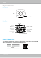
VIVOTEK Physical Description Front Panel Lens Built-in Microphone Back Panel Audio Out Status LED Microphone In SD/SDHC Card Slot Ethernet 10/100 RJ45 Socket Power Cord Socket Recessed Reset Button General I/O Terminal Block External/Internal MIC Switch General I/O Terminal Block This Network Camera provides a general I/O terminal block which is used to connect external input / output devices. The pin definitions are described below.
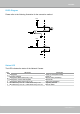
VIVOTEK DI/DO Diagram Please refer to the following illustration for the connection method. 12V PIN 1 Power+12V PIN 2 Digital output +12V PIN 3 Digital input PIN 4 Ground Status LED The LED indicates the status of the Network Camera. Item 1 2 3 4 5 LED status Steady Red Red LED unlighted Steady Red + Blink Green every 1 sec. Steady Red + Green LED unlighted Steady Red + Blink Green every 2 sec. Blink Red every 0.15 sec. + Blink Green every 1 sec. Blink Red every 0.15 sec. + Blink Green every 0.
VIVOTEK Hardware Reset Status LED Recessed Reset Button The reset button is used to reset the system or restore the factory default settings. Sometimes resetting the system can return the camera to normal operation. If the system problems remain after reset, restore the factory settings and install again. Reset: Press and release the recessed reset button with a paper clip or thin object. Wait for the Network Camera to reboot.
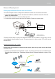
VIVOTEK Network Deployment Setting up the Network Camera over the Internet This section explains how to configure the Network Camera over an Internet connection. 1. If you have external devices such as sensors and alarms, make the connection from the general I/O terminal block. 2. Connect the camera to a switch via Ethernet cable. 3. Connect the supplied power cable from the Network Camera to a power outlet.
VIVOTEK 2. In this case, if the Local Area Network (LAN) IP address of your Network Camera is 192.168.0.3, please forward the following ports for the Network Camera on the router. ■ HTTP port ■ RTSP port ■ RTP port for audio ■ RTCP port for audio ■ RTP port for video ■ RTCP port for video If you have changed the port numbers on the Network page, please open the ports accordingly on your router. For information on how to forward ports on the router, please refer to your router’s user’s manual. 3.
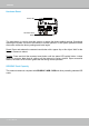
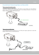
VIVOTEK Set up the Network Camera through Power over Ethernet (PoE) When using a PoE-enabled switch The Network Camera is PoE-compliant, which allows it to be powered via a single Ethernet cable. If your switch/router supports PoE, refer to the following illustration to connect the Network Camera to a PoE-enabled switch/router.
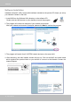
VIVOTEK Software Installation Installation Wizard 2 (IW2), free-bundled software included on the product CD, helps you set up your Network Camera on the LAN. 1. Install IW2 from the Software Utility directory on the software CD. Double click the IW2 shortcut on your desktop to launch the program. 2. The program will conduct an analysis of your network environment. After your network environment is analyzed, please click Next to continue the program. 3.
VIVOTEK Ready to Use 1. Access the Network Camera from the LAN. 2. Retrieve live video through a web browser or recording software.
VIVOTEK Accessing the Network Camera This chapter explains how to access the Network Camera through web browsers, RTSP players, 3GPP-compatible mobile devices, and VIVOTEK recording software. Using Web Browsers Use Installation Wizard 2 (IW2) to access to the Network Cameras installed on the LAN. If your network environment is not a LAN, follow these steps to access the Network Camera: 1. Launch your web browser (eg. Microsoft® Internet Explorer, Mozilla Firefox, or Netscape). 2.
VIVOTEK ► By default, the Network Camera is not password-protected. To prevent unauthorized access, it is highly recommended to set a password for the Network Camera. For more information about how to enable password protection, please refer to Security on page 26. ► If you see a dialog box indicating that your security settings prohibit running ActiveX ® Controls, please enable the ActiveX ® Controls for your browser. 1. Choose Tools > Internet Options > Security > Custom Level. 2.
VIVOTEK Using RTSP Players To view the MPEG-4 streaming media using RTSP players, you can use one of the following applications that support RTSP streaming. Quick Time Player Real Player VLC media player 1. Launch the RTSP player. mpegable Player 2. Choose File > Open URL. A URL dialog box will pop up. 3.
VIVOTEK Using 3GPP-compatible Mobile Devices To view the streaming media through 3GPP-compatible mobile devices, make sure the Network Camera can be accessed over the Internet. For more information on how to set up the Network Camera over the Internet, please refer to Setting up the Network Camera over the Internet on page 7. To utilize this feature, please check the following settings on your Network Camera: 1.
VIVOTEK Using VIVOTEK Recording Software The product software CD also contains VIVOTEK’s recording software, allowing simultaneous monitoring and video recording for multiple Network Cameras. Please install the recording software, then launch the program to add the Network Camera to the Channel list. For detailed information about how to use the recording software, please refer to the user’s manual of the software or download the manual from http://www.vivotek.com.
VIVOTEK Main Page This chapter explains the layout of the main page. It is composed of the following sections: VIVOTEK INC. Logo, Host Name, Camera Control Area, Configuration Area, Menu, and Live Video Window. VIVOTEK INC. Logo Host Name Camera Control Area Live View Window Configuration Area VIVOTEK INC. Logo Click this logo to visit the VIVOTEK website. Host Name The host name can be customized to fit your needs. For more information, please refer to System on page 24.
VIVOTEK Configuration Area Client Settings: Click this button to access the client setting page. For more information, please refer to Client Settings on page 21. Configuration: Click this button to access the configuration page of the Network Camera. It is suggested that a password be applied to the Network Camera so that only the administrator can configure the Network Camera. For more information, please refer to Configuration on page 23.
VIVOTEK Pause: Pause the transmission of the streaming media. The button becomes the after clicking the Pause button. Stop: Stop the transmission of the streaming media. Click the transmission. Resume button Resume button to continue Start MP4 Recording: Click this button to record video clips in MP4 file format. Press the Stop MP4 Recording button to end recording. When you exit the web browser, video recording stops accordingly.
VIVOTEK Snapshot: Click this button to capture and save still images. The captured images will be displayed in a pop-up window. Right-click the image and choose Save Picture As to save it in JPEG (*.jpg) or BMP (*.bmp) format. Digital Zoom: Click and uncheck “Disable digital zoom” to enable the zoom operation. The navigation screen indicates the part of the image being magnified. To control the zoom level, drag the slider bar. To move to a different area you want to magnify, drag the navigation screen.
VIVOTEK Client Settings This chapter explains how to select the stream transmission mode and saving options on the local computer. When finished with the settings on this page, click Save on the page bottom to enable the settings. MPEG-4 Media Options Select to stream video or audio data or both. This is enabled only when the video mode is set to MPEG-4.
VIVOTEK MP4 Saving Options Users can record live video as they are watching by clicking Here, you can specify the storage destination and file name. Start MP4 Recording on the main page. Folder: Specify the storage destination for the recorded video files. File name prefix: Enter the text that will be appended to the front of the video file name. Add date and time suffix to the file name: Select this option to append the date and time to the end of the file name.
VIVOTEK Configuration Click Configuration on the main page to enter the camera setting pages. Note that only Administrators can access the configuration page. VIVOTEK offers an easy-to-use user interface that helps you set up your network camera with minimal effort. To simplify the setting procedure, two types of user interfaces are available: Advanced Mode for professional users and Basic Mode for entry-level users.
VIVOTEK Advanced Mode Configuration List Click to switch to Basic Mode Firmware Version Each function on the configuration list will be explained in the following sections. Those functions that are displayed only in Advanced Mode are marked with Advanced Mode . If you want to set up advanced functions, please click [Advanced Mode] on the bottom of the configuration list to quickly switch over.
VIVOTEK System Time Keep current date and time: Select this option to preserve the current date and time of the Network Camera. The Network Camera’s internal real-time clock maintains the date and time even when the system power is turned off. Sync with computer time: Select this option to synchronize the date and time of the Network Camera with the local computer. The read-only date and time of the PC is displayed when updated. Manual: The administrator can enter the date and time manually.
VIVOTEK Security This section explains how to enable password protection and create multiple accounts. Root Password The administrator account name is “root”, which is permanent and can not be deleted. If you want to add more accounts in the Manage User section, please set the password for the “root” account first. 1. Type the password in both text boxes, then click Save to enable password protection. 2.
VIVOTEK HTTPS (Hypertext Transfer Protocol over SSL) Advanced Mode This section explains how to enable authentication and encrypted communication over SSL (Secure Socket Layer). It helps protect streaming data transmission over the Internet on higher security level. Enable HTTPS Check this item to enable HTTPS communication, then select a connection option: "HTTP & HTTPS" or "HTTPS only". Note that you have to create and install a certificate first in the second section before clicking the Save button.
VIVOTEK 4. The Certificate Information will automatically de displayed in the third section as shown below. You can click Property to view detailed information about the certificate. 5. Click Home to return to the main page. Change the address from “http://” to “https://“ in the address bar and press Enter on your keyboard. A Security Alert dialog box will pop up. Click OK or Yes to enable HTTPS. https:// https://192.168.5.151/index.
VIVOTEK Create a self-signed certificate manually 1. Select this option. 2. Click Create to open the Create Certificate page, then click Save to generate the certificate. 3. The Certificate Information will automatically be displayed in the third column as shown below. You can click Property to see detailed information about the certificate. Create a certificate and install : Select this option if you want to create a certificate from a certificate authority. 1. Select this option. 2.
VIVOTEK 3. If you see the following Information bar, click OK on click on the Information bar at the top of the page to allow pop-ups. 4. The pop-up window shows an example of a certificate request.
VIVOTEK 5. Look for a trusted certificate authority that issues digital certificates. Enroll the Network Camera. Wait for the certificate authority to issue an SSL certificate; click Browse... to search for the issued certificate, then click Upload in the second section. NOTE ► How do I cancel the HTTPS settings? 1. Uncheck Enable HTTPS secure connection in the first column and click Save; a warning dialog box will pop up. 2. Click OK to disable HTTPS. 3.
VIVOTEK SNMP (Simple Network Management Protocol) Advanced Mode This section explains how to use the SNMP on the network camera. The Simple Network Management Protocol is an application layer protocol that facilitates the exchange of management information between network devices. It helps network administrators to remotely manage network devices and find, solve network problems with ease. ■ The SNMP consists of the following three key components: 1.
VIVOTEK Network This section explains how to configure a wired network connection for the Network Camera. Network Type LAN Select this option when the Network Camera is deployed on a local area network (LAN) and is intended to be accessed by local computers. The default setting for the Network Type is LAN. Rememer to click Save when you complete the Network setting.
VIVOTEK Mega-pixel Network Camera (192.168.5.151) Enable UPnP port forwarding: To access the Network Camera from the Internet, select this option to allow the Network Camera to open ports on the router automatically so that video streams can be sent from the LAN. To utilize this feature, make sure that your router supports UPnPTM and it is activated. PPPoE (Point-to-point over Ethernet) Select this option to configure your Network Camera to make it accessible from anywhere with an Internet connection.
VIVOTEK ► Steps to enable the UPnP TM user interface on your computer: Note that you must log on to the computer as a system administrator to install the UPnP TM components. 1. Go to Start, click Control Panel, then click Add or Remove Programs. 2. In the Add or Remove Programs dialog box, click Add/Remove Windows Components. 3. In the Windows Components Wizard dialog box, select Networking Services and click Details.
VIVOTEK 4. In the Networking Services dialog box, select Universal Plug and Play and click OK. 5. Click Next in the following window. 6. Click Finish. UPnP TM is enabled. ► How does UPnP TM work? UPnP TM networking technology provides automatic IP configuration and dynamic discovery of devices added to a network. Services and capabilities offered by networked devices, such as printing and file sharing, are available to each other without the need for cumbersome network configuration.
VIVOTEK Enable IPv6 Select this option and click Save to enable IPv6 settings. Please note that this only works if your network environment and hardware equipment support IPv6. The browser should be Microsoft® Internet Explorer 6.5, Mozilla Firefox 3.0 or above. When IPv6 is enabled, by default, the network camera will listen to router advertisements and be assigned with a link-local IPv6 address accordingly. IPv6 Information: Click this button to obtain the IPv6 information as shown below.
VIVOTEK Please follow the steps below to link to an IPv6 address: 1. Open your web browser. 2. Enter the link-global or link-local IPv6 address in the address bar of your web browser. 3. The format should be: http://[2001:0c08:2500:0002:0202:d1ff:fe04:65f4]/ IPv6 address 4. Press Enter on the keyboard or click Refresh button to refresh the webpage.
VIVOTEK IEEE 802.1x Advanced Mode Enable this function if your network environment uses IEEE 802.1x, which is a port-based network access control. The network devices, intermediary switch/access point/hub, and RADIUS server must support and enable 802.1x settings. The 802.1x standard is designed to enhance the security of local area networks, which provides authentication to network devices (clients) attached to a network port (wired or wireless).
VIVOTEK 3. When all settings are complete, move the Network Camera to the protected LAN by connecting it to an 802.1x enabled switch. The devices will then start the authentication automatically. NOTE ► The authentication process for 802.1x: 1. The Certificate Authority (CA) provides the required signed certificates to the Network Camera (the supplicant) and the RADIUS Server (the authentication server). 2. A Network Camera requests access to the protected LAN using 802.
VIVOTEK QoS (Quality of Service) Advanced Mode Quality of Service refers to a resource reservation control mechanism, which guarantees a certain quality to different services on the network. Quality of service guarantees are important if the network capacity is insufficient, especially for real-time streaming multimedia applications. Quality can be defined as, for instance, a maintained level of bit rate, low latency, no packet dropping, etc.
VIVOTEK QoS/DSCP (the DiffServ model) DSCP-ECN defines QoS at Layer 3 (Network Layer). The Differentiated Services (DiffServ) model is based on packet marking and router queuing disciplines. The marking is done by adding a field to the IP header, called the DSCP (Differentiated Services Codepoint). This is a 6-bit field that provides 64 different class IDs. It gives an indication of how a given packet is to be forwarded, known as the Per Hop Behavior (PHB).
VIVOTEK HTTP Advanced Mode To utilize HTTP authentication, make sure that your have set a password for the Network Camera first; please refer to Security on page 26 for details. Authentication: Depending on your network security requirements, the Network Camera provides two types of security settings for an HTTP transaction: basic and digest. If basic authentication is selected, the password is sent in plain text format, where there is a potential risk of being intercepted.
VIVOTEK URL command -- http://:/ For example, when the Access name for stream 2 is set to video2.mjpg: 1. Launch Mozilla Firefox or Netscape. 2. Type the URL command in the address bar. Press Enter. 3. The JPEG images will be displayed in your web browser. http://192.168.5.151/video2.
VIVOTEK Note that as JPEG only transmits a series of JPEG images to the client; to enable the two-way audio function, make sure the video mode is set to “MPEG-4” on the Audio and Video Settings page and the media option is set to “Video and Audio” on the Client Settings page. Please refer to Client Settings on page 21 and Audio and Video Settings on page 48.
VIVOTEK RTSP Streaming To utilize RTSP streaming authentication, make sure that you have set a password for the Network Camera first; please refer to Security on page 26 for details. Authentication: Depending on your network security requirements, the Network Camera provides three types of security settings for streaming via RTSP protocol: disable, basic, and digest. If basic authentication is selected, the password is sent in plain text format, but there can be potential risks of it being intercepted.
VIVOTEK RTSP port /RTP port for video, audio/ RTCP port for video, audio ■ RTSP (Real-Time Streaming Protocol) controls the delivery of streaming media. By default, the port number is set to 554. ■ The RTP (Real-time Transport Protocol) is used to deliver video and audio data to the clients. By default, the RTP port for video is set to 5556 and the RTP port for audio is set to 5558.
VIVOTEK DDNS This section explains how to configure the dynamic domain name service for the Network Camera. DDNS is a service that allows your Network Camera, especially when assigned with a dynamic IP address, to have a fixed host and domain name. DDNS: Dynamic Domain Name Service Enable DDNS: Select this option to enable the DDNS setting. Provider: Select a DDNS provider from the provider drop-down list. VIVOTEK offers Safe100.net, a free dynamic domain name service, to VIVOTEK customers.
VIVOTEK [Register] Successfully Your account information has been mailed to registered e-mail address 4. Select Enable DDNS and click Save to enable the setting. ■ CustomSafe100 VIVOTEK offers documents to establish a CustomSafe100 DDNS server for distributors and system integrators. You can use CustomSafe100 to register a dynamic domain name if your distributor or system integrators offer such services. 1. In the DDNS column, select CustomSafe100 from the drop-down list. 2.
VIVOTEK Access List Advanced Mode This section explains how to control access permission by verifying the client PC’s IP address. General Settings Maximum number of concurrent streaming connection(s) limited to: Simultaneous live viewing for 1~10 clients (including stream 1 and stream 2). The default value is 10. If you modify the value and click Save, all current connections will be disconnected and automatically attempt to re-link (IE Explore or Quick Time Player).
VIVOTEK ■ Refresh: Click this button to refresh all current connections. ■ Add to deny list: You can select entries from the Connection Status list and add them to the Deny List to deny access. Please note that those checked connections will only be disconnected temporarily and will automatically try to re-link again (IE Explore or Quick Time Player). If you want to enable the denied list, please check Enable access list filtering and click Save in the first column.
VIVOTEK Network: This rule allows the user to assign a network address and corresponding subnet mask to the Allow/Deny List. For example: IP address 192.168.2.x will be blocked. Range: This rule allows the user to assign a range of IP addresses to the Allow/Deny List. This rule is only applied to IPv4. For example: ■ Delete Allowed/Denied list: In the Delete Allowed List or Delete Denied List column, make a selection and click Delete.
VIVOTEK Audio and Video This section explains how to cofigure the audio and video settings of the Network Camera. It is composed of the following two columns: Video Settings and Audio Settings. Video Settings Video title: Enter a name that will be displayed on the title bar of the live video. Video Title Title and Time Video 17:08:56 2008/06/25 Color: Select to display color or black/white video streams.
VIVOTEK Overlay title and time stamp on video: Select this option to place the video title and time on the video streams. Note that when the frame size is set to 176 x 144 as shown in the picture below, only the time will be stamped on the video streams. 17:08:56 2008/06/25 Image Settings Advanced Mode Click Image settings to open the Image Settings page. On this page, you can tune the White balance, Brightness, Saturation, Contrast, and Sharpness settings for the video.
VIVOTEK ■ Auto The Network Camera automatically adjusts the color temperature of the light in response to different light sources. The white balance setting defaults to Auto and works well in most situations. ■ Keep current value Follow the steps below to manually set the white balance to compensate for the ambient lighting conditions. 1. Set the White balance to Auto and click Save. 2.
VIVOTEK Privacy Mask Advanced Mode Click Privacy Mask to open the settings page. On this page, you can block out sensitive zones to address privacy concerns. ■ To set the privacy mask windows, follow the steps below: 1. Click New to add a new window. 2. Use the mouse to size and drag-drop the window, which is recommended to be at least twice the size of the object (height and width) you want to cover. 3. Enter a Window Name and click Save to enable the setting. 4.
VIVOTEK Sensor Settings Advanced Mode Click Sensor Settings to open the Sensor Settings page. On this page, you can set the maximum exposure time, exposure level, and AGC (Auto Gain Control) settings. You can configure two sets of sensor settings: one for normal situations, the other for special situations, such as day/night/schedule mode. Exposure ■ Maximum Exposure Time: Select a proper maximum exposure time according to the light source of the surroundings.
VIVOTEK Viewing Window Advanced Mode This Network Camera supports multiple streams with frame size ranging from 176 x 144 to 1600 x 1200. The definition of multiple streams: ■ Stream 1: Users can define the "Region of Interest" (viewing region) and the "Output Frame Rate" (size of the live view window). ■ Stream 2: Users can define the "Region of Interest" (viewing region) and the "Output Frame Rate" (size of the live view window).
VIVOTEK Click Viewing Window to open the viewing region settings page. On this page, you can set the Region of Interest and the Output Frame Size for stream 1 ~ 3. Please follow the steps below to set up those settings for a stream: 1. Select a stream which you want to set up the viewing region. If you want to stream out the video to a mobile device, please select stream 3. 2. Select a Region of Interest from the drop-down list.
VIVOTEK Options of Video Choose either Video quality first or Video frame rate first for the video streams. Note: Select Video quality first will reduce the maximum frame rate to 15 fps. Select Video frame rate first will limit the frame size to 800x600 and clear the settings in the Viewing Window. Video quality settings for stream 1 ~ 4 Advanced Mode Click the items to display the detailed video quality settings.
VIVOTEK ■ Frame size You can set up different video resolution for different viewing devices. For example, set a smaller frame size and lower bit rate for remote viewing on mobile phones and a larger video size and a higher bit rate for live viewing on web browsers. Note that a larger frame size takes up more bandwidth. ■ Maximum frame rate This limits the maximum refresh frame rate per second. Set the frame rate higher for smoother video quality.
VIVOTEK ■ Video quality The video quality can be adjusted to the following settings: Medium, Standard, Good, Detailed, and Excellent. You can also select Customize and manually enter a value. NOTE ► Video quality and fixed quality refers to the compression rate, so a lower value will produce higher quality. Audio Settings Mute: Select this option to disable audio transmission from the Network Camera to all clients.
VIVOTEK Motion Detection This section explains how to configure the Network Camera to enable motion detection. A total of three motion detection windows can be configured. Follow the steps below to enable motion detection: 1. Click New to add a new motion detection window. 2. In the Window Name text box, enter a name for the motion detection window. ■ To move and resize the window, drag and drop your mouse on the window. ■ To delete window, click X on the top right corner of the window. 3.
VIVOTEK A green bar indicates that even though motions have been detected, the event has not been triggered because the image variations still fall under the defined threshold. Percentage = 30% This motion detection window will also be displayed on the Event Settings page. You can go to Application > Event Settings > Trigger to choose it as a trigger source. Please refer to page 75 for detailed information.
VIVOTEK Camera Tampering Detection This section explains how to set up camera temper detection. With tamper detection, the camera is capable of detecting incidents such as redirection, blocking or defocusing, or even spray paint. Please follow the steps below to set up the camera tamper detection function: 1. Check Enable camera tampering detection. 2. Enter the tamper trigger duration. (10 sec. ~ 10 min.
VIVOTEK Camera Control This section explains how to control the Network Camera’s e-Pan/Tilt/Zoom operation. It allows users to quickly move the focus to a target area for close-up viewing without moving the camera physically. Select Stream: Select one of the stream 1~3 to set up the e-PTZ control. Please note that each stream can be set up with its own e-preset positions and e-patrol settings.
VIVOTEK E-Preset Positions A total of 20 preset positions can be configured. You can select preset positions for the camera to patrol. Please follow the steps below to preset a position: 1. Adjust the shooting area to the desired position using the buttons on the right side of the window. 2. Enter a name for the preset position, which allows for up to forty characters. Click Add to enable the settings. The preset positions will be displayed under the Preset Location list on the left-hand side. 3.
VIVOTEK E-Patrol Settings You can select some e-preset positions for the Network Camera to patrol. Please follow the steps below to set up a patrol schedule: 1. Click a preset location on the list and click Select. 2. The selected preset location will be displayed on the Source list. 3. Set the Dwelling time for the preset location during auto patrol. You can also manually enter a value in the blank and click Update. 4. Repeat step 1 and 3 to select additional preset locations. 5.
VIVOTEK Home page x1.0 ■ The e-Preset Positions will also be displayed on the home page. Select one from the drop-down list, and the Network Camera will move to the selected e-preset position. ■ If you have set up different e-preset positions for stream 1~3, you can select one of the video streams to display its separate e-preset positions. Global View In addition to using the e-PTZ control panel, you can also use the mouse to drag or resize the floating frame to pan/tilt/zoom the viewing region.
VIVOTEK Homepage Layout Advanced Mode This section explains how to set up your own customized homepage layout. Preview This column shows the settings of your homepage layout. You can manually select the background and font colors in Theme Options (the third column on this page). The settings will be displayed automatically in this Preview field. The following shows the homepage using the default settings: ■ Hide Powered by VIVOTEK: If you check this item, it will be removed from the homepage.
VIVOTEK Theme Options Here you can change the color of your homepage layout. There are three types of preset patterns for you to choose from. The new layout will simultaneously appear in the Preview filed. Click Save to enable the settings.
VIVOTEK ■ Follow the steps below to set up a customized homepage: 1. Click Custom on the left column. 2. Click the field where you want to change the color on the right column. Color Selector Custom Pattern 3. The palette window will pop up as shown below. 2 3 1 4 4. Drag the slider bar and click on the left square to select a desired color. 5. The selected color will be displayed in the corresponding fields and in the Preview column. 6. Click Save to enable the settings.
VIVOTEK Application Advanced Mode This section explains how to configure the Network Camera to responds to particular situations (events). A typical application is that when a motion is detected, the Network Camera sends buffered images to an FTP server or e-mail address as notifications. In the illustration on the right, an event can be Action triggered by many sources, such as motion detection Event Trigger or external digital input devices. When an event is ex.
VIVOTEK Event Settings In the Event Settings column, click Add to open the Event Settings page. On this page, you can arrange three elements -- Trigger, Schedule, and Action to set an event. A total of 3 event settings can be configured. Event name: Enter a name for the event setting. Enable this event: Select this option to enable the event setting. Priority: Select the relative importance of this event (High, Normal, or Low). Events with a higher priority setting will be executed first.
VIVOTEK An event is an action initiated by a user-defined trigger source; it is the causal arrangement of the following three elements: Trigger, Event Schedule, and Action. Trigger This is the cause or stimulus which defines when to trigger the Network Camera. The trigger source can be configured to use the Network Camera’s built-in motion detection mechanism or external digital input devices. There are several choices of trigger sources as shown below.
VIVOTEK ■ Recording notify This option allows the Network Camera to trigger when the recording disk is full or when recording starts to rewrite older data. If you want receive Recording notify message, please refer to page 84 for detailed information. ■ Camera tampering detection This option allows the Network Camera to trigger when the camera detects that is is being tampered with. To enable this function, you need to configure the Tampering Detection option first.
VIVOTEK To set an event with recorded video or snapshots, it is necessary to configure the server and media settings so that the Network Camera will know what action to take (such as which server to send the media files to) when a trigger is activated. ■ Add Server / Add Media Click Add Server to configure Server Settings. For more information, please refer to Server Settings on page 79. Click Add Media to configure Media Settings. For more information, please refer to Media Settings on page 82.
VIVOTEK When completed, click Save to enable the settings and click Close to exit the Event Settings page. The new event settings / server settings / media settings will appear in the event drop-down list on the Application page. Here is an example of the Application page with an event setting: When the Event Status is ON, once an event is triggered by motion detection, the Network Camera will automatically send snapshots via e-mail.
VIVOTEK Server Settings Click Add Server on Event Settings page to open the Server Setting page. On this page, you can specify where the notification messages are sent when a trigger is activated. A total of 5 server settings can be configured. Server name: Enter a name for the server setting. Server Type There are four choices of server types available: Email, FTP, HTTP, and Network storage. Select the item to display the detailed configuration options. You can configure either one or all of them.
VIVOTEK FTP: Select to send the media files to an FTP server when a trigger is activated. ■ Server address: Enter the domain name or IP address of the FTP server. ■ Server port By default, the FTP server port is set to 21. It can also be assigned to another port number between 1025 and 65535. ■ User name: Enter the login name of the FTP account. ■ Password: Enter the password of the FTP account. ■ Remote folder name Enter the folder where the media file will be placed.
VIVOTEK HTTP: Select to send the media files to an HTTP server when a trigger is activated. ■ URL: Enter the URL of the HTTP server. ■ User name: Enter the user name if necessary. ■ Password: Enter the password if necessary. To verify if the HTTP settings are correctly configured, click Test. The result will be shown in a pop-up window as below. If successful, you will receive a test.txt file on the HTTP server. Click Save to enable the settings, then click Close to exit the page.
VIVOTEK Media Settings Click Add Media on the Event Settings page to open the Media Settings page. On this page, you can specify the type of media that will be sent when a trigger is activated. A total of 5 media settings can be configured. Media name: Enter a name for the media setting. Media Type There are three media types available: Snapshot, Video Clip, and System log. Select the item to display the detailed configuration options. You can configure either or all of them.
VIVOTEK Video clip: Select to send video clips when a trigger is activated. ■ Source: Select to record video clips from stream 1 ~ 4. ■ Pre-event recording The Network Camera has a buffer area; it temporarily holds data up to a certain limit. Enter a number to decide the duration of recording before a trigger is activated. Up to 9 seconds can be set. ■ Maximum duration Specify the maximum recording duration in seconds. Up to 10 seconds can be set.
VIVOTEK Recording notify message: Select to send a recording notification message when a trigger is activated. The following is an example of a recording notification message (.txt file), which shows a list of deleted previously-recorded data due to cycle recording. When completed, click Save to enable the settings and click Close to exit this page. The new media settings will appear on the Event Settings page. You can continue to select a server and media type for the event.
VIVOTEK The following is an example of a file destination with video clips: The format is: YYYYMMDD Click to open the directory 20081120 20081121 20081122 Click to delete all recorded data Click to delete selected items Click 20081120 to open the directory: The format is: HH (24r) Click to open the file list for that hour Click to go back to the previous level of the directory Click to delete selected items Click to delete all recorded data The format is: File name prefix + Minute (mm) You can set u
VIVOTEK Recording Advanced Mode This section explains how to configure the recording settings for the Network Camera. Recording Settings Insert your SD card and click here to test NOTE ► Before setting up this page, please set up the Network Storage on the Server Settings page first. ► Please remember to format your SD card when using for the first time. Please refer to page 89 for detailed information. Network Storage Setting Click Server to open the Server Settings page and follow the steps below: 1.
VIVOTEK If successful, you will receive a test.txt file on the network storage server. 3. Enter a server name. 4. Click Save to enable the settings and click Close to exit the page. Recording Settings Click Add to open the recording setting page. On this page, you can define the recording source, recording schedule and recording capacity. A total of 2 recording settings can be configured. Recording name: Enter a name for the recording setting.
VIVOTEK Source: Select the recording source (stream 1 or stream 2). Recording Schedule: Specify the recording duration. ■ Select the days of the week. ■ Select the recording start and end times in 24-hr time format. Destination: You can select the SD card or network storage to strore the recorded video files. Capacity: You can choose either the entire free space available or limit the recording size. The recording size limit must be larger than the reserved amount for cyclic recording.
VIVOTEK Local Storage Advanced Mode This section explains how to manage the local storage on the Network Camera. Here you can view SD card status, search for recorded files to playback, download, etc. no SD card SD Card Management SD card status: This column shows the status and reserved space of your SD card. Please remember to format the SD card when using for the first time.
VIVOTEK SD card control ■ Enable cyclic storage: Check this item if you want to enable cyclic recording. When the maximum capacity is reached, the oldest file will be overwritten by the latest one. ■ Enable automatic disk cleanup: Check this item and enter the number of days you wish to retain a file. For example, if you enter “7 days”, the recorded files will be stored on the SD card for 7 days. Click Save to enable your settings.
VIVOTEK Search Results The following is an example of search results. There are four columns: Trigger time, Media type, Trigger type, and Locked. Click to sort the search results in either direction. Enter a key word to filter the Numbers of entries displayed on one page search results Highlight an item Click to switch pages View: Click on a search result which will highlight the selected item in purple as shown above. Click the View button and a media window will pop up to play back the selected file.
VIVOTEK Download: Click on a search result to highlight the selected item in purple as shown above. Then click the Download button and a file download window will pop up for you to save the file. JPEGs to AVI: This functions only applies to “JPEG“ format files such as snapshots. You can select several snapshots from the list, then click this button. Those snapshots will be converted into an AVI file. Lock/Unlock: Select the desired search results, then click this button.
VIVOTEK System Log Advanced Mode This section explains how to configure the Network Camera to send the system log to the remote server as backup. Remote Log You can configure the Network Camera to send the system log file to a remote server as a log backup. Before utilizing this feature, it is suggested that the user install a log-recording tool to receive system log messages from the Network Camera. An example is Kiwi Syslog Daemon. Visit http://www.kiwisyslog. com/kiwi-syslog-daemon-overview/.
VIVOTEK View Parameters Advanced Mode The View Parameters page lists the entire system’s parameters in alphabetical order. If you need technical assistance, please provide the information listed on this page.
VIVOTEK Maintenance This chapter explains how to restore the Network Camera to factory default, upgrade firmware version, etc. Reboot This feature allows you to reboot the Network Camera, which takes about one minute to complete. When completed, the live video page will be displayed in your browser. The following message will be displayed during the reboot process. If the connection fails after rebooting, manually enter the IP address of the Network Camera in the address field to resume the connection.
VIVOTEK Export / Upload Files Advanced Mode This feature allows you to Export / Upload daylight saving time rules, custom language files, and setting backup files. Export daylight saving time configuration file: Click to set the start and end time of DST. Follow the steps below to export: 1. In the Export files column, click Export to export the daylight saving time configuration file from the Network Camera. 2. A file download dialog will pop up as shown below.
VIVOTEK Upload daylight saving time rule: Click Browse… and specify the XML file to upload. If the incorrect date and time are assigned, you will see the following warning message when uploading the file to the Network Camera. The following message is displayed when attempting to upload an incorrect file format. Export language file: Click to export language strings. VIVOTEK provides nine languages: English, Deutsch, Español, Français, Italiano, 日本語, Português, 簡体中文, and 繁體中文.
VIVOTEK The following message is displayed when the upgrade has succeeded. Reboot system now!! This connection will close. The following message is displayed when you have selected an incorrect firmware file. Starting firmware upgrade... Do not power down the server during the upgrade. The server will restart automatically after the upgrade is completed. This will take about 1 - 5 minutes.
VIVOTEK Appendix URL Commands for the Network Camera Overview For some customers who already have their own web site or web control application, the Network Camera/Video Server can be easily integrated through URL syntax. This section specifies the external HTTP-based application programming interface. The HTTP-based camera interface provides the functionality to request a single image, control camera functions (PTZ, output relay etc.), and get and set internal parameter values.
VIVOTEK General CGI URL Syntax and Parameters CGI parameters are written in lower-case and as one word without any underscores or other separators. When the CGI request includes internal camera parameters, these parameters must be written exactly as they are named in the camera or video server. The CGIs are organized in functionally-related directories under the cgi-bin directory. The file extension .cgi is required. Syntax: http:///cgi-bin/[/...]/.
VIVOTEK http:///cgi-bin/viewer/getparam.cgi?[] [&…] http:///cgi-bin/operator/getparam.cgi?[] [&…] http:///cgi-bin/admin/getparam.cgi?[] [&…] Where the should be [_] or [.]. If you do not specify any parameters, all the parameters on the server will be returned. If you specify only , the parameters of the related group will be returned.
VIVOTEK Set Server Parameter Values Note: The access right depends on the URL directory. Method: GET/POST Syntax: http:///cgi-bin/anonymous/setparam.cgi? = [&=…][&update=][&return=] http:///cgi-bin/viewer/setparam.cgi? = [&=…][&update=] [&return=] http:///cgi-bin/operator/setparam.
VIVOTEK =\r\n [] Only the parameters that you set and are readable will be returned. Example: Set the IP address of server to 192.168.0.123: Request: http://myserver/cgi-bin/admin/setparam.cgi?network_ipaddress=192.168.0.123 Response: HTTP/1.0 200 OK\r\n Content-Type: text/html\r\n Context-Length: 33\r\n \r\n network.ipaddress=192.168.0.
VIVOTEK positive Integer Any number between 0 and (232 – 1) integer primary key SQLite data type. A 32-bit signed integer. The value is assigned a unique integer by the server. text SQLite data type. The value is a text string, stored using the database encoding (UTF-8, UTF-16BE or UTF-16-LE). NOTE: The camera should not be restarted when parameters are changed.
VIVOTEK -200: GMT-05:00 Eastern Time, New York, Toronto -201: GMT-05:00 Bogota, Lima, Quito, Indiana -180: GMT-04:30 Caracas -160: GMT-04:00 Atlantic Time, Canada, La Paz, Santiago -140: GMT-03:30 Newfoundland -120: GMT-03:00 Brasilia, Buenos Aires, Georgetown, Greenland -80: GMT-02:00 Mid-Atlantic -40: GMT-01:00 Azores, Cape_Verde_IS.
VIVOTEK Kong, Kuala Lumpur, Singapore, Taipei 360: GMT 09:00 Osaka, Sapporo, Tokyo, Seoul, Yakutsk 380: GMT 09:30 Adelaide, Darwin 400: GMT 10:00 Brisbane, Canberra, Melbourne, Sydney, Guam, Vladivostok 440: GMT 11:00 Magadan, Solomon Is., New Caledonia 480: GMT 12:00 Aucklan, Wellington, Fiji, Kamchatka, Marshall Is. 520: GMT 13:00 Nuku'Alofa formertimezonein -489 ~ 529 6/6 dex daylight_enable Record the last time zone for time jump when changing time zones.
VIVOTEK restoreexceptnet 7/6 Restore the system parameters to default values except (ipaddress, subnet, router, dns1, dns2, pppoe). This command can cooperate with other “restoreexceptXYZ” commands. When cooperating with others, the system parameters will be restored to the default value except for a union of the combined results. restoreexceptdst 7/6 Restore the system parameters to default values except all daylight saving time settings.
VIVOTEK IP7133-SECN). If there is no specific value, this field should not be added. supportscriptversion string[40] 0/7 The version of the supported script language. scriptversion string[40] 0/7 Current script language version. webpageversion string[40] 0/7 Current webpage version. language_count 0/7 Number of webpage languages available on the server. language_i<0~(count string[16] 0/7 Available language lists.
VIVOTEK Group: do_i<0~(ndo-1)> (capability.ndo > 0) NAME VALUE SECURITY DESCRIPTION (get/set) normalstate open, 1/1 Indicate open circuit or closed circuit grounded (inactive status) Group: viewmode NAME VALUE SECURITY DESCRIPTION (get/set) busymode 1/1 Enable snapshot mode to allow more users to view video. refreshinterval 1~99 1/1 The interval for busy mode video refresh in seconds. defaultsource 0~(n-1), quad 1/1 Default channel of video source (capability.
VIVOTEK dns2. ipaddress 6/6 IP address of server. subnet 6/6 Subnet mask. router 6/6 Default gateway. dns1 6/6 Primary DNS server. dns2 6/6 Secondary DNS server. wins1 6/6 Primary WINS server. wins2 6/6 Secondary WINS server. SECURITY DESCRIPTION Subgroup of network: ieee8021x NAME VALUE (get/set) enable 6/6 Enable/disable IEEE 802.
VIVOTEK dscp_video 0~7 6/6 Video channel for DSCP dscp_audio 0~7 6/6 Audio channel for DSCP dscp_eventalarm 0~7 6/6 Event/alarm channel for DSCP dscp_management 0~7 6/6 Management channel for DSCP Subgroup of network: ipv6 NAME VALUE SECURITY DESCRIPTION (get/set) enable 6/6 Enable IPv6. addonipaddress 6/6 IPv6 IP address. addonprefixlen 0~128 6/6 IPv6 prefix length. addonrouter 6/6 IPv6 router address.
VIVOTEK s4_accessname string[32] 1/6 Http server push access name for stream 5 (capability.protocol.spush_mjpeg =1 and video.stream.count>4) anonymousviewing 1/6 Enable anoymous streaming viewing. Subgroup of network: https NAME VALUE SECURITY DESCRIPTION (get/set) port 443, 1025 ~ 65535 6/6 HTTPS port. Subgroup of network: rtsp NAME VALUE SECURITY DESCRIPTION (get/set) port 554, 1025 ~ 65535 1/6 RTSP port. (capability.protocol.
VIVOTEK Subgroup of network_rtsp_s<0~(n-1)>: multicast, n is stream count (capability.protocol.rtp.multicast=1) NAME VALUE SECURITY DESCRIPTION (get/set) alwaysmulticast 4/4 Enable always multicast. ipaddress 4/4 Multicast IP address. videoport 1025 ~ 65535 4/4 Multicast video port. audioport 1025 ~ 65535 4/4 Multicast audio port. ttl 1 ~ 255 4/4 Mutlicast time to live value.
VIVOTEK 255.255.255.255 allow_i<0~9>_end 1.0.0.0 ~ 6/6 Allowed ending IPv4 address for connection. 6/6 Denied starting IPv4 address for connection. 6/6 Denied ending IPv4 address for connection. 255.255.255.255 deny_i<0~9>_start 1.0.0.0 ~ 255.255.255.255 deny_i<0~9>_end 1.0.0.0 ~ 255.255.255.255 ipv6_allow_i<0~9> String[44] 6/6 Allowed IPv6 address for connection. ipv6_deny_i<0~9> String[44] 6/6 Denied IPv6 address for connection.
VIVOTEK Bit 0 => Support camera control function; 0(not support), 1(support) Bit 1 => Built-in or external camera; 0 (external), 1(built-in) Bit 2 => Support pan operation; 0(not support), 1(support) Bit 3 => Support tilt operation; 0(not support), 1(support) Bit 4 => Support zoom operation; 0(not support), 1(support) Bit 5 => Support focus operation; 0(not support), 1(support) text string[16] 1/4 Enclose caption. imprinttimestamp 4/4 Overlay time stamp on video.
VIVOTEK 8: brightness (capability_nvideoinprofile > 0) profile_i<0~(k-1)>_ 0~2 4/4 agc Set auto gain control to: 0: 2X level 1: 4X level 2: 8X level (capability_nvideoinprofile > 0) profile_i<0~(k-1)>_ 4/4 autoiris s<0~(m-1)>_codec Enable auto Iris (capability_nvideoinprofile > 0) mpeg4, mjpeg 4/4 Video codec type. s<0~(m-1)>_resolu 176x144, 4/4 Video resolution in pixels. tion 320x240, 4/4 Intra frame period in milliseconds.
VIVOTEK Group: audio (product dependent) NAME VALUE SECURITY DESCRIPTION (get/set) duplexmode full, 4/4 Full => full-duplex half, Half => half-duplex post, Post => simplex talk only get Get => simplex listen only (capability.audioput>0 and capability.audioin>0) sendclientaudio 4/4 Enable audio send from active client to all other clients. (capability.audioput>0 and capability.audioin>0) lowbandwidth 4/4 Improve low bandwidth environment support.
VIVOTEK Group: image_c<0~(n-1)> for n channel products NAME VALUE SECURITY DESCRIPTION (get/set) brightness -5 ~ 5 4/4 Adjust brightness of image according to mode settings. saturation -5 ~ 5 4/4 Adjust saturation of image according to mode settings. contrast -5 ~ 5 4/4 Adjust contrast of image according to mode settings. sharpness -5 ~ 5 4/4 Adjust sharpness of image according to mode settings. IBPE_edgeenable 4/4 Enable edge enhancement.
VIVOTEK IBPE_nrenable 4/4 Preview of adjusting enabling noise reduction. IBPE_nrmode 1~3 4/4 Preview of adjusting noise reduction mode. 1 => DeGaussian 2 => DeImpulse 3 => DeGaussian + DeImpulse IBPE_nrstrength 1 ~ 63 4/4 Preview of adjusting noise reduction strength. 1 is minimum and 63 is maximum. videoin_whitebalance auto, 4/4 Preview of white balance adjustment of image manual videoin_restoreatwb according to mode settings.
VIVOTEK profile_i<0~(m-1)>_win_i<0~2> string[14] 4/4 Name of motion window. 0 ~ 320 4/4 Left coordinate of window position. 0 ~ 240 4/4 Top coordinate of window position. 0 ~ 320 4/4 Width of motion detection window. 0 ~ 240 4/4 Height of motion detection window. 0 ~ 100 4/4 Percent of motion detection window. 0 ~ 100 4/4 Sensitivity of motion detection window.
VIVOTEK key _serverna service provider. string[128] 6/6 The server name for safe100. me (This field only exists if the provider is customsafe100) Group: upnppresentation NAME VALUE SECURITY DESCRIPTION (get/set) enable 6/6 Enable or disable the UPNP presentation service. Group: upnpportforwarding NAME VALUE SECURITY DESCRIPTION (get/set) enable 6/6 Enable or disable the UPNP port forwarding service.
VIVOTEK rocomm string[14] 6/6 V1, V2c Read only community. rwcomm string[14] 6/6 V1, V2c Read write community. adminauthtype 0~2 6/6 Authority type for root authentication. admindpvcy string[64] 6/6 Root data encryption key. enableadpvcy 6/6 Enable root data encryption key. userauthtype 0~2 6/6 User authority authentication. userdpvcy string[64] 6/6 User data encryption key. enableudpvcy 6/6 Enable user data encryption key.
VIVOTEK win_i<0~4>_width 0 ~ 320/352 4/4 Width of privacy mask window. win_i<0~4>_height 0 ~ 240/288 4/4 Height of privacy mask window. win_i<0~4>_color 0 ~ 13 4/4 Color of privacy mask window. Group: capability NAME VALUE SECURITY DESCRIPTION (get/set) api_httpversion 0200a 0/7 The HTTP API version. bootuptime 0/7 Server bootup time. nir 0, 0/7 Number of IR interfaces. 0/7 Number of PIRs. 0/7 Number of digital inputs. 0/7 Number of digital outputs.
VIVOTEK 0(not support), 1(support) Bit 5 => Support focus operation; 0(not support), 1(support) Bit 6 => Support iris operation; 0(not support), 1(support) Bit 7 => External or built-in PT; 0(built-in), 1(external) Bit 8 => Invalidate bit 1 ~ 7; 0(bit 1 ~ 7 are valid), 1(bit 1 ~ 7 are invalid) Bit 9 => Reserved bit; Invalidate lens_pan, Lens_tilt, lens_zoon, lens_focus, len_iris.
VIVOTEK Bit 1 => Support focus in UI. Bit 2 => External or built-in focus function; 0(built-in), 1(external). Bit 3 => Support auto focus in UI. lens_iris 0/7 A 32-bit integer, each bit can be set separately as follows: Bit 0 => Support iris. Bit 1 => Support iris in UI. Bit 2 => External or build-in iris function; 0(build-in), 1(external). Bit 3 => Support auto iris in UI. npreset 0/7 Number of preset locations.
VIVOTEK maximum frame rate separated by commas> videoin_codec videoout_codec cancellation. audio_extmic 0/7 Indicate whether to support external microphone input. audio_linein 0/7 Indicate whether to support external line input.
VIVOTEK wireless_802dot11g 0/7 Indicate whether to support wireless 802.11g. wireless_encrypt_wep 0/7 Indicate whether to support wireless WEP. wireless_encrypt_wpa 0/7 Indicate whether to support wireless WPA. wireless_encrypt_wpa 0/7 Indicate whether to support wireless WPA2. 0/7 Indicate whether to support the upgrade 2 derivative_brand function for the derivative brand.
VIVOTEK trigger boot, 6/6 Indicate the trigger condition: di, “boot” = System boot motion, “di”= Digital input seq, “motion” = Video motion detection visignal, “seq” = Periodic condition pir, “visignal” = Video input signal loss. recnotify, “pir” = PIR detection. audioswitch, “recnotify” = Recording notification. tampering “audioswitch” = Audio switch. “tampering” = Tamper detection. di 6/6 Indicate which DI detects. This field is required when trigger condition is “di”.
VIVOTEK action_do_i<0~(ndo-1) 0, 1 6/6 Enable or disable trigger digital output. 1~999 6/6 Duration of the digital output trigger in seconds. action_cf_enable 0. 1 6/6 Enable media write on CF. action_cf_folder string[128] 6/6 Path to store media. action_cf_media NULL, 0~4 6/6 Index of the attached media. action_cf_datefolder 6/6 Enable this to create folders by date, time, and hour >_enable action_do_i<0~(ndo-1) >_duration automatically.
VIVOTEK email_username string[64] 6/6 Username to log in to the server. email_passwd string[64] 6/6 Password of the user. email_senderemail string[128] 6/6 Email address of the sender. email_recipientemail string[128] 6/6 Email address of the recipient. ns_location string[128] 6/6 Location to upload or store the media. ns_username string[64] 6/6 Username to log in to the server. ns_passwd string[64] 6/6 Password of the user.
VIVOTEK Group: recording_i<0~1> PARAMETER VALUE SECURITY DESCRIPTION (get/set) name string[40] 6/6 Identification of this entry. enable 0, 1 6/6 Enable or disable this recording. priority 0, 1, 2 6/6 Indicate the priority of this recording: “0” indicates low priority. “1” indicates normal priority. “2” indicates high priority. source 6/6 Indicate the source of the media stream. 0 = First stream. 1 = Second stream 2 = Third stream 3 = Fourth stream, etc.
VIVOTEK weekday 6/6 Indicate which weekday is scheduled. One bit represents one weekday. bit0 (LSB) = Saturday bit1 = Friday bit2 = Thursday bit3 = Wednesday bit4 = Tuesday bit5 = Monday bit6 = Sunday For example, to detect events on Friday and Sunday, set weekday as 66. begintime hh:mm 6/6 Start time of the weekly schedule. endtime hh:mm 6/6 End time of the weekly schedule. (00:00~24:00 indicates schedule always on) prefix string[16] 6/6 Indicate the prefix of the filename.
VIVOTEK enable 6/6 To enable or disable secure HTTP. policy 6/6 If the value is 1, it will force HTTP connection redirect to HTTPS connection method auto, 6/6 auto => Create self-signed certificate manual, automatically. install manual => Create self-signed certificate manually. install => Create certificate request and install. status -2 ~ 1 6/6 Specify the https status.
VIVOTEK Group: eptz_c<0~(n-1)> for n channel product. PARAMETER VALUE SECURITY DESCRIPTION (get/set) osdzoom 1/4 Indicates multiple of zoom in is “on-screen display” or not smooth 1/4 Indicates ePTZ is smooth or not. tiltspeed -5 ~ 5 1/7 Tilt speed (It should be set by eCamCtrl.cgi rather than by setparam.cgi.) panspeed -5 ~ 5 1/7 Pan speed (It should be set by eCamCtrl.cgi rather than by setparam.cgi.) zoomspeed -5 ~ 5 1/7 Zoom speed (It should be set by eCamCtrl.
VIVOTEK [&do3=][&do4=][&return=] Where state is 0 or 1; “0” means inactive or normal state, while “1” means active or triggered state. PARAMETER VALUE DESCRIPTION do 0, 1 0 – Inactive, normal state 1 – Active, triggered state return Redirect to the page after the parameter is assigned. The can be a full URL path or relative path according to the current path. If you omit this parameter, it will redirect to an empty page.
VIVOTEK Request: http://myserver/cgi-bin/dido/getdi.cgi?di1 Response: HTTP/1.0 200 OK\r\n Content-Type: text/plain\r\n Content-Length: 7\r\n \r\n di1=1\r\n Query Status of the Digital Output Note: This request requires Viewer privileges. Method: GET/POST Syntax: http:///cgi-bin/dido/getdo.cgi?[do0][&do1][&do2][&do3] If no parameter is specified, all the digital output statuses will be returned. Return: HTTP/1.
VIVOTEK Content-Length: 7\r\n \r\n do1=1\r\n Capture Single Snapshot Note: This request requires Normal User privileges. Method: GET/POST Syntax: http:///cgi-bin/viewer/video.jpg?[channel=][&resolution=] [&quality=] If the user requests a size larger than all stream settings on the server, this request will fail. PARAMETER VALUE DEFAULT DESCRIPTION channel 0~(n-1) 0 The channel number of the video source. resolution
VIVOTEK method=&username=[&userpass=][&privilege=] [&privilege=][…][&return=] PARAMETER VALUE DESCRIPTION method Add Add an account to the server. When using this method, the “username” field is necessary. It will use the default value of other fields if not specified. Delete Remove an account from the server. When using this method, the “username” field is necessary, and others are ignored. edit Modify the account password and privilege.
VIVOTEK \r\n \r\n Configuration File (optional) Note: This request requires Administrator privileges. Method: GET/POST Syntax: http:///cgi-bin/admin/configfile.cgi?[format=] Server will return the most up-to-date configuration file. PARAMETER VALUE DEFAULT DESCRIPTION format xml xml Format for the config file. Return: HTTP/1.
VIVOTEK Server will accept the file named to upgrade the firmware and return with if indicated. ePTZ Camera Control Note: This request requires camctrl privileges. Method: GET/POST Syntax: http:///cgi-bin/camctrl/eCamCtrl.
VIVOTEK speedapp 1~5 Set the auto pan/patrol speed. return Redirect to the page after the parameter is assigned. The can be a full URL path or relative path according to the current path. ePTZ Preset Locations Note: This request requires Operator privileges. Method: GET/POST Syntax: http:///cgi-bin/operator/ePreset.
VIVOTEK HTTP/1.0 200 OK\r\n Content-Type: text/plain\r\n Content-Length: \r\n \r\n Model=\r\n CapVersion=0200\r\n PARAMETER(supported VALUE DESCRIPTION system.firmwareversion Model name of the server. capability version) Model Ex:IP3133-VVTK-0100a CapVersion MMmm, MM is major version from 00 ~ 99 Capability field version. mm is minor version from 00 ~ 99 ex: 0100 IP Filtering Note: This request requires Administrator access privileges.
VIVOTEK deleteallow Remove allowed IP address range from server. If start and end parameters are specified, it will try to remove the matched IP address. If index is specified, it will try to remove the address from given index position. [start, end] parameters have higher priority then the [index] parameter. deletedeny Remove denied IP address range from server. If start and end parameters are specified, it will try to remove the matched IP address.
VIVOTEK http:///_accessname> For RTSP (MP4), the user needs to input the URL below into an RTSP compatible player. rtsp:///_accessname> “m” is the stream number. For details on streaming protocol, please refer to the “control signaling” and “data format” documents. Storage managements (capability.storage.dbenabled=1) Note: This request requires administrator privileges.
VIVOTEK destPath Optional. Indicate the file location in camera. Please embrace your input value with single quotes. Ex. destPath =’/mnt/auto/CF/NCMF/abc.mp4’ resolution Optional. Indicate the media file resolution. Please embrace your input value with single quotes. Ex. resolution=’800x600’ isLocked Optional. Indicate if the file is locked or not. 0: file is not locked. 1: file is locked. A locked file would not be removed from UI or cyclic storage.
VIVOTEK Ex. label=1 Ex. Delete records whose key numbers are 1, 4, and 8. http:///cgi-bin/admin/lsctrl.cgi?cmd=delete&label=1&label=4&label=8 Command: update PARAMETER VALUE DESCRIPTION label Required. Identify the designated record. Ex. label=1 isLocked Required. Indicate if the file is locked or not. Ex. Update records whose key numbers are 1 and 5 to be locked status. http:///cgi-bin/admin/lsctrl.
Technical Specifications Specifications System .CPU: Mozart 120 SoC .Flash: 16MB .RAM: 128MB + 128MB .Embedded OS: Linux 2.6 Lens .CS-mount, f = 4.2 mm, F1.8, Fixed Angle of View .71.2° (horizontal) Shutter Time .1/5 sec. to 1/40,000 sec. Image Sensor .1/3.2” CMOS sensor in 1600x1200 resolution Minimum Illumination .0.3 Lux / F1.
VIVOTEK Technology License Notice MPEG-4 AAC Technology THIS PRODUCT IS LICENSED UNDER THE MPEG-4 AAC AUDIO PATENT LICENSE. THIS PRODUCT MAY NOT BE DECOMPILED, REVERSE-ENGINEERED OR COPIED, EXCEPT WITH REGARD TO PC SOFTWARE, OF WHICH YOU MAY MAKE SINGLE COPIES FOR ARCHIVAL PURPOSES. FOR MORE INFORMATION, PLEASE REFER TO HTTP://WWW.VIALICENSING.COM.
VIVOTEK Electromagnetic Compatibility (EMC) FCC Statement This device compiles with FCC Rules Part 15. Operation is subject to the following two conditions. ■ This device may not cause harmful interference, and ■ This device must accept any interference received, including interference that may cause undesired operation. This equipment has been tested and found to comply with the limits for a Class B digital device, pursuant to Part 15 of the FCC Rules.