IP8152 Fixed Network Camera User’s Manual 1.3MP • Compact Size • Supreme Night Visibility Rev. 1.
VIVOTEK Table of Contents Overview ����������������������������������������������������������������������������������������������������������������������������������������������������� 4 Revision History �������������������������������������������������������������������������������������������������������������������������������������� 4 Read Before Use ������������������������������������������������������������������������������������������������������������������������������������� 5 Package Contents �
VIVOTEK Appendix ���������������������������������������������������������������������������������������������������������������������������������������������������� 125 URL Commands for the Network Camera ������������������������������������������������������������������������������������������������ 125 Technical Specifications ��������������������������������������������������������������������������������������������������������������������������� 211 Technology License Notice ������������������������
VIVOTEK Overview VIVOTEK IP8152 features a brand new box camera design concept from VIVOTEK, with a compact size and a multitude of features. The small size makes it an easy to fit into different types of enclosures with different lens options, with the ability to fit a CS-mount lens making it a flexible solution for all types of surveillance.
VIVOTEK Read Before Use The use of surveillance devices may be prohibited by law in your country. The Network Camera is not only a high-performance web-ready camera but can also be part of a flexible surveillance system. It is the user’s responsibility to ensure that the operation of such devices is legal before installing this unit for its intended use. It is important to first verify that all contents received are complete according to the Package Contents listed below.
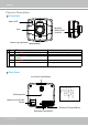
VIVOTEK Physical Description Front Panel Status LED MicroSD/ SDHC/SDXC Card Slot Lens Mount ring adjustment LED Definitions Item LED status Description 4 5 Network failed Restoring defaults 1 2 3 Steady Red Green LED blinks every 1 sec. Green and RED blink consecutively every 0.15 sec. Steady Red Orange blinks every 0.15 sec.
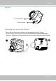
VIVOTEK Lens Focus Controller Zoom Controller Mounting the Lens to the Camera 1. Mount the lens by turning it clockwise onto the camera mount until it stops. 2. Connect the iris control cable to the socket. Connect the iris control cable before power-on. Otherwise, you will not be able to access the exposure-related settings.
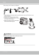
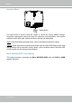
VIVOTEK Mounting the Camera to Stand 1. Use the holes on the camera stand to mark drill holes on the wall. Drill holes on your preferred location. 2. Hammer in the included plastic anchors. 3. Install the camera stand to wall or ceiling by driving screws through it. 4. Attach the camera to stand by turning the stand and the fastening rings. IMPORTANT: Record the MAC address before installing the camera.
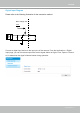
VIVOTEK Digital Input Diagram Please refer to the following illustration for the connection method. Max. voltage: 40V 3.3V DI+ Digital input DIDI-: Ground Connect a digital input device to the input pins of the camera. From the Applications > Digital Input page, you can let camera report the current signal status as High or Low, Open or Grounded, to determine the signal’s Normal status during operation.
VIVOTEK Hardware Reset Reset Button The reset button is used to reset the system or restore the factory default settings. Sometimes resetting the system can return the camera to normal operation. If the system problems remain after reset, restore the factory settings and install again. Reset: Press and release the reset button. Wait for the Network Camera to reboot. Restore: Press and hold the recessed reset button until the status LED rapidly blinks.
VIVOTEK Network Deployment Power over Ethernet (PoE) When using a PoE-enabled switch The Network Camera is PoE-compliant, allowing transmission of power and data via a single Ethernet cable. Follow the below illustration to connect the Network Camera to a PoE-enabled switch via Ethernet cable. PoE Switch POWER COLLISION 1 2 3 4 5 LINK RECEIVE PARTITION When using a non-PoE switch Use a PoE power injector (optional) to connect between the Network Camera and a non-PoE switch.
VIVOTEK Internet connection via a router Before setting up the Network Camera over the Internet, make sure you have a router and follow the steps below. 1. Connect your Network Camera behind a router, the Internet environment is illustrated below. Regarding how to obtain your IP address, please refer to Software Installation on page 14 for details. WAN (Wide Area Network ) Internet Router IP address : from ISP POWER COLLISION 1 2 3 4 5 IP address : 192.168.0.3 Subnet mask : 255.255.255.
VIVOTEK Configure the router, virtual server or firewall, so that the router can forward any data coming into a preconfigured port number to a network camera on the private network, and allow data from the camera to be transmitted to the outside of the network over the same path. From Forward to 122.146.57.120:8000 192.168.2.10:80 122.146.57.120:8001 192.168.2.11:80 ... ... When properly configured, you can access a camera behind the router using the HTTP request as follows: http://122.146.57.
VIVOTEK Software Installation Installation Wizard 2 (IW2), free-bundled software included on the product CD, helps you set up your Network Camera on the LAN. IW2 1. Install IW2 under the Software Utility directory from the software CD. Double-click the IW2 shortcut on your desktop to launch the program. Installation Wizard 2 2. The program will conduct an analysis of your network environment. After your network environment is analyzed, please click Next to continue the program. 3.
VIVOTEK Ready to Use 1. A browser session with the Network Camera should prompt as shown below. 2. You should be able to see live video from your camera. You may also install the 32-channel recording software from the software CD in a deployment consisting of multiple cameras. For its installation details, please refer to its related documents. 3. Unscrew the zoom controller to adjust the zoom factor. Upon completion, tighten the zoom controller. 4. Unscrew the focus controller to adjust the focus range.
VIVOTEK NOTE: If you prefer other lens for your IP8152, please notice the specifications below. 1. If you select a different lens, the distance between the flange of the lens and the IR cut filter on the camera should be smaller than 7.5mm. If the lens protrudes too much from the bottom of the lens module, it may hit the IR Cut Filter, or result in out of focus when adjusting the focus controller. 2. A vari-focal lens may protrude from the bottom of screw mount when tuning the focus puller.
VIVOTEK Installed into Housing 1. Attach the bracket to the back of the camera by resting the foam pads on the top and to the back of the camera. Secure the bracket by driving a hex socket screw. The camera can be installed into VIVOTEK's housings, such as the AE-211/-232/-233/-234/-235 series. 2. Attach the T-bracket and the camera to the camera bracket. Place the camera lens in the front as close as possible to the enclosure's tempered glass window.
VIVOTEK Accessing the Network Camera This chapter explains how to access the Network Camera through web browsers, RTSP players, 3GPP-compatible mobile devices, and VIVOTEK recording software. Using Web Browsers Use Installation Wizard 2 (IW2) to access the Network Cameras on LAN. If your network environment is not a LAN, follow these steps to access the Netwotk Camera: 1. Launch your web browser (e.g., Microsoft® Internet Explorer or Mozilla Firefox). 2.
VIVOTEK ► By default, the Network Camera is not password-protected. To prevent unauthorized access, it is highly recommended to set a password for the Network Camera. For more information about how to enable password protection, please refer to Security on page 78. ► If you see a dialog box indicating that your security settings prohibit running ActiveX ® Controls, please enable the ActiveX ® Controls for your browser. 1. Choose Tools > Internet Options > Security > Custom Level. 2.
VIVOTEK IMPORTANT: • Currently the Network Camera utilizes 32-bit ActiveX plugin. You CAN NOT open a management/view session with the camera using a 64-bit IE browser. • If you encounter this problem, try execute the Iexplore.exe program from C:\ Windows\SysWOW64. A 32-bit version of IE browser will be installed. • On Windows 7, the 32-bit explorer browser can be accessed from here: C:\Program Files (x86)\Internet Explorer\iexplore.
VIVOTEK Using RTSP Players To view the MPEG-4 streaming media using RTSP players, you can use one of the following players that support RTSP streaming. Quick Time Player VLC VLC media player 1. Launch the RTSP player you prefer. mpegable Player 2. Choose File > Open URL. A URL dialog box will prompt. 3. The address format is: rtsp://:/ VIVOTEK’s network cameras support simultaneous playback of 2 to 5 video streams.
VIVOTEK Using 3GPP-compatible Mobile Devices To view the streaming media through 3GPP-compatible mobile devices, make sure the Network Camera can be accessed over the Internet. For more information on how to set up the Network Camera over the Internet, please refer to Setup the Network Camera over the Internet on page 12. To utilize this feature, please check the following settings on your Network Camera: 1.
VIVOTEK Using VIVOTEK Recording Software The product software CD also contains an ST7501 recording software, allowing simultaneous monitoring and video recording for multiple Network Cameras. Please install the recording software; then launch the program to add the Network Camera to the Channel list. For detailed information about how to use the recording software, please refer to the user’s manual of the software or download it from http://www.vivotek.com.
VIVOTEK Main Page This chapter explains the layout of the main page. It is composed of the following sections: VIVOTEK INC. Logo, Host Name, Camera Control Area, Configuration Area, Menu, and Live Video Window. VIVOTEK INC. Logo Resize Buttons Host Name Configuration Area Camera Control Area Live View Window Hide Button VIVOTEK INC. Logo Click this logo to visit the VIVOTEK website. Host Name The host name can be customized to fit your needs. For more information, please refer to System on page 33.
VIVOTEK Configuration Area Client Settings: Click this button to access the client setting page. For more information, please refer to Client Settings on page 28. Configuration: Click this button to access the configuration page of the Network Camera. It is suggested that a password be applied to the Network Camera so that only the administrator can configure the Network Camera. For more information, please refer to Configuration on page 32.
VIVOTEK Global View: Click on this item to display the Global View window. The Global View window contains a full view image (the largest frame size of the captured video) and a floating frame (the viewing region of the current video stream). The floating frame allows users to control the e-PTZ function (Electronic Pan/ Tilt/Zoom). For more information about e-PTZ operation, please refer to E-PTZ Operation on page 91.
VIVOTEK ■ The following window is displayed when the video mode is set to MJPEG: Video Title Title and Time Video (HTTP-V) 2012/06/25 17:08:56 Time Video 17:08:56 2012/06/25 Video Control Buttons Video Title: The video title can be configured. For more information, please refer to Media > Image on page 45. Time: Display the current time. For more information, please refer to Media > Image on page 45. Title and Time: Video title and time can be stamped on the streaming video.
VIVOTEK Client Settings This chapter explains how to select the stream transmission mode and saving options on the local computer. When completed with the settings on this page, click Save on the page bottom to enable the settings. H.264 / MPEG-4 Media Options H.264/MPEG-4 Media Options Select to stream video or audio data or both. This is enabled only when the video mode is set to H.264 or MPEG-4. H.264 / MPEG-4 Protocol Options H.
VIVOTEK MP4 Saving Options Users can record live video as they are watching it by clicking page. Here you can specify the storage destination and file name. Start MP4 Recording on the main Folder: Specify a storage destination for the recorded video files. File name prefix: Enter the text that will be appended to the front of the video file name. Add date and time suffix to the file name: Select this option to append the date and time to the end of the file name.
VIVOTEK Joystick settings Enable Joystick Connect a joystick to a USB port on your management computer. Supported by the plug-in (Microsoft’s DirectX), once the plug-in for the web console is loaded, it will automatically detect if there is any joystick on the computer. The joystick should work properly without installing any other driver or software. Then you can begin to configure the joystick settings of connected devices. Please follow the instructions below to enable joystick settings. 1.
VIVOTEK Buttons Configuration Click the Configure Buttons button, a window will prompt as shown below. Please follow the steps below to configure your joystick buttons: 1. Select a button number from the Button # pull-down menu. Tips If you are not sure of the locations of each button, use the Properties window in the Game Controllers utility. 2. Select a corresponding action, such as Patrol or Preset#. 3. Click the Assign button to assign an action to the button.
VIVOTEK Configuration Click Configuration on the main page to enter the camera setting pages. Note that only Administrators can access the configuration page. VIVOTEK offers an easy-to-use user interface that helps you set up your network camera with minimal effort. To simplify the setting procedure, two types of user interfaces are available: Advanced Mode for professional users and Basic Mode for entry-level users.
VIVOTEK Advanced Mode Navigation Area Configuration List Click to switch to Basic Mode Firmware Ver- Each function on the configuration list will be explained in the following sections. Those functions that are displayed only in Advanced Mode are marked with Advanced Mode . If you want to set up advanced functions, please click [Advanced Mode] on the bottom of the configuration list to quickly switch over.
VIVOTEK System time Keep current date and time: Select this option to preserve the current date and time of the Network Camera. The Network Camera’s internal real-time clock maintains the date and time even when the power of the system is turned off. Synchronize with computer time: Select this option to synchronize the date and time of the Network Camera with the local computer. The read-only date and time of the PC is displayed as updated. Manual: The administrator can enter the date and time manually.
VIVOTEK System > Homepage layout Advanced Mode This section explains how to set up your own customized homepage layout. General settings This column shows the settings of your hompage layout. You can manually select the background and font colors in Theme Options (the second tab on this page). The settings will be displayed automatically in this Preview field.
VIVOTEK Theme Options Here you can change the color of your homepage layout. There are three types of preset patterns for you to choose from. The new layout will simultaneously appear in the Preview filed. Click Save to enable the settings.
VIVOTEK ■ Follow the steps below to set up the customed homepage: 1. Click Custom on the left column. 2. Click the field where you want to change the color on the right column. Color Selector Custom Pattern 3. The palette window will pop up as shown below. 2 3 1 4 4. Drag the slider bar and click on a spot on the left square to select a desired color. 5. The selected color will be displayed in the corresponding fields and in the Preview column. 6. Click Save to enable the settings.
VIVOTEK System > Logs Advanced Mode This section explains how to configure the Network Camera to send the system log to a remote server as backup. Log server settings Follow the steps below to set up the remote log: 1. Select Enable remote log. 2. In the IP address text box, enter the IP address of the remote server. 2. In the port text box, enter the port number of the remote server. 3. When completed, click Save to enable the setting.
VIVOTEK You can install the included ST7501 recording software, which provides an Event Management function group for delivering event messages via emails, GSM short messages, onscreen event panel, or to trigger an alarm, etc. For more information, refer to the ST7501 User Manual.
VIVOTEK Access log Access log displays the access time and IP address of all viewers (including operators and administrators) in a chronological order. The access log is stored in the Network Camera’s buffer area and will be overwritten when reaching a certain limit. System > Parameters Advanced Mode The View Parameters page lists the entire system’s parameters. If you need technical assistance, please provide the information listed on this page.
VIVOTEK System > Maintenance This chapter explains how to restore the Network Camera to factory default, upgrade firmware version, etc. General settings > Upgrade firmware This feature allows you to upgrade the firmware of your Network Camera. It takes a few minutes to complete the process. Note: Do not power off the Network Camera during the upgrade! Follow the steps below to upgrade the firmware: 1. Download the latest firmware file from the VIVOTEK website. The file is in .pkg file format. 2.
VIVOTEK General settings > Restore This feature allows you to restore the Network Camera to factory default settings. Network: Select this option to retain the Network Type settings (please refer to Network Type on page 59). Daylight Saving Time: Select this option to retain the Daylight Saving Time settings (please refer to Import/Export files below on this page). Custom Language: Select this option to retain the Custom Language settings.
VIVOTEK 3. Open the file with Microsoft® Notepad and locate your time zone; set the start and end time of DST. When completed, save the file. In the example below, DST begins each year at 2:00 a.m. on the second Sunday in March and ends at 2:00 a.m. on the first Sunday in November. Update daylight saving time rules: Click Browse… and specify the XML file to update. If the incorrect date and time are assigned, you will see the following warning message when uploading the file to the Network Camera.
VIVOTEK The following message is displayed when attempting to upload an incorrect file format. Export language file: Click to export language strings. VIVOTEK provides nine languages: English, Deutsch, Español, Français, Italiano, 日本語, Português, 簡体中文, and 繁體中文. Update custom language file: Click Browse… and specify your own custom language file to upload. Export configuration file: Click to export all parameters for the device and user-defined scripts.
VIVOTEK Media > Image Advanced Mode This section explains how to configure the image settings of the Network Camera. It is composed of the following four columns: General settings, Image settings, Exposure, and Privacy mask. General settings Video title: Enter a name that will be displayed on the title bar of the live video as the picture shown below.
VIVOTEK Day/Night Settings Switch to B/W in night mode Select this to enable the Network Camera to automatically switch to Black/White display during night mode. IR cut filter With a removable IR-cut filter, this Network Camera can automatically remove the filter to let IR light into the sensor during low light conditions. ■ Auto mode The Network Camera automatically removes the filter by judging the level of ambient light.
VIVOTEK Image settings On this page, you can tune the White balance, Image adjustment and low light compensation. Image Setting 1: For normal situations Image Setting 2: For special situations White balance: Adjust the value for the best color temperature. ■ You may follow the steps below to adjust the white balance to the best color temperature. 1.
VIVOTEK Activated period: Select the period of time this profile setting will apply to. Please manually enter a range of time in a day, tune the White Balance and Image adjustment settings as previously described, and then check Save for the configuration to take effect. Exposure Advanced Mode On this page, you can set the Measurement window, Exposure level, Exposure time, and Gain control settings.
VIVOTEK Measurement Window: This function allows user to set measurement window(s) for low light compesation. ■ Full view: Calculate the full range of view and offer appropriate light compesation. ■ BLC (Back Light Compensation): This option allows you to use the center of the current view as the measuring area. The measuring window refers to “weighted window“ where the lighting condition within the particular area is taken into account.
VIVOTEK ■ Iris mode (available for IP8152 using a DC-iris lens): Select Indoor or Outdoor iris mode to adapt to the installation. The preset iris aperture setting will apply. You can click Restore to recall the original settings without incorporating the changes. When completed with the settings on this page, click Save to enable the settings. If you want to configure another sensor setting for the schedule mode, please click Profile to open the Profile of exposure settings page as shown below.
VIVOTEK Privacy mask Advanced Mode Click Privacy Mask to open the settings page. On this page, you can block out sensitive zones to address privacy concerns. 2010/12/09 17:08:56 2010/12/09 17:08:56 ■ To set the privacy mask windows, follow the steps below: 1. Click New to add a new window. 2. You can use the mouse cursor to size and drag-drop the window, which is recommended to be at least twice the size of the object (height and width) you want to cover. 3.
VIVOTEK Media > Video Advanced Mode Stream settings This Network Camera supports multiple streams with a frame size ranging from 176 x 144 to 1280 x 1024. The definition of multiple streams: ■ Stream 1: Users can define the "Region of Interest" (viewing region) and the "Output Frame Size" (size of the live view window). It is like selecting a portion of the image captured by sensor to display only the selection portion.
VIVOTEK Media > Video NOTE: ► All the items in the “Region of Interest” should not be larger than the “Output Frame Size“ (current maximum resolution). ■ The parameters of the multiple streams: Stream 1 Stream 2 Region of Interest Output frame size 1280 X 1024 ~ 176 x 144 (Selectable) fixed 1280 X 1024 ~ 176 x 144 (Selectable) fixed When completed with the settings in the Viewing Window, click Save to enable the settings and click Close to exit the window.
VIVOTEK Click the stream item to display the detailed information. The maximum frame size will follow your settings in the Viewing Window sections. This Network Camera offers real-time H.264 and MJPEG compression standards (Dual Codec) for real-time viewing. If H.264 mode is selected, the video is streamed via RTSP protocol. There are several parameters for you to adjust the video performance: ■ Frame size You can set up different video resolution for different viewing devices.
VIVOTEK The frame rate will decrease if you select a higher resolution. ■ Intra frame period Determine how often to plant an I frame. The shorter the duration, the more likely you will get better video quality, but at the cost of higher network bandwidth consumption. Select the intra frame period from the following durations: 1/4 second, 1/2 second, 1 second, 2 seconds, 3 seconds, and 4 seconds.
VIVOTEK If JPEG mode is selected, the Network Camera sends consecutive JPEG images to the client, producing a moving effect similar to a filmstrip. Every single JPEG image transmitted guarantees the same image quality, which in turn comes at the expense of variable bandwidth usage. Because the media contents are a combination of JPEG images, no audio data is transmitted to the client.
VIVOTEK The bandwidth utilization is configurable to match a selected level, resulting in mutable video quality performance. The bit rates are selectable at the following rates: 20Kbps, 30Kbps, 40Kbps, 50Kbps, 64Kbps, 128Kbps, 256Kbps, 512Kbps, 768Kbps, 1Mbps, 2Mbps, 3Mbps, 4Mbps, 6Mbps, and 8Mbps. You can also select Customize and manually enter a value.
VIVOTEK Media > Audio Advanced Mode Audio Settings Mute: Select this option to disable audio transmission from the Network Camera to all clients. Note that if muted, no audio data will be transmitted even if audio transmission is enabled on the Client Settings page. In that case, the following message is displayed: External microphone input gain: Select the gain of the external audio input according to ambient conditions by dragging the pointer on the slide bar. Audio type: Advanced Mode . ■ G.
VIVOTEK Network > General settings This section explains how to configure a wired network connection for the Network Camera. Network Type LAN Select this option when the Network Camera is deployed on a local area network (LAN) and is intended to be accessed by local computers. The default setting for the Network Type is LAN. Please remember to click Save when you complete the Network setting.
VIVOTEK Primary DNS: The primary domain name server that translates hostnames into IP addresses. Secondary DNS: Secondary domain name server that backups the Primary DNS. Primary WINS server: The primary WINS server that maintains the database of computer names and IP addresses. Secondary WINS server: The secondary WINS server that maintains the database of computer names and IP addresses.
VIVOTEK NOTENOTE: ► If the default ports are already used by other devices connected to the same router, the Network Camera will select other ports for the Network Camera. ► If UPnP TM is not supported by your router, you will see the following message: Error: Router does not support UPnP port forwarding. ► Steps to enable the UPnP TM user interface on your computer: Note that you must log on to the computer as a system administrator to install the UPnP TM components. 1.
VIVOTEK 4. In the Networking Services dialog box, select Universal Plug and Play and click OK. 5. Click Next in the following window. 6. Click Finish. UPnP TM is enabled. ► How does UPnP TM work? UPnP TM networking technology provides automatic IP configuration and dynamic discovery of devices added to a network. Services and capabilities offered by networked devices, such as printing and file sharing, are available among each other without the need for cumbersome network configuration.
VIVOTEK PPPoE (Point-to-point over Ethernet) Select this option to configure your Network Camera to make it accessible from anywhere as long as there is an Internet connection. Note that to utilize this feature, it requires an account provided by your ISP. Follow the steps below to acquire your Network Camera’s public IP address. 1. Set up the Network Camera on the LAN. 2. Go to Configuration > Event > Event settings > Add server (please refer to Add server on page 104) to add a new email or FTP server. 3.
VIVOTEK Enable IPv6 Select this option and click Save to enable IPv6 settings. Please note that this only works if your network environment and hardware equipment support IPv6. The browser should be Microsoft® Internet Explorer 6.5, Mozilla Firefox 3.0 or above. When IPv6 is enabled, by default, the network camera will listen to router advertisements and be assigned with a link-local IPv6 address accordingly. IPv6 Information: Click this button to obtain the IPv6 information as shown below.
VIVOTEK Please follow the steps below to link to an IPv6 address: 1. Open your web browser. 2. Enter the link-global or link-local IPv6 address in the address bar of your web browser. 3. The format should be: http://[2001:0c08:2500:0002:0202:d1ff:fe04:65f4]/ IPv6 address 4. Press Enter on the keyboard or click Refresh button to refresh the webpage.
VIVOTEK Port HTTPS port: By default, the HTTPS port is set to 443. It can also be assigned to another port number between 1025 and 65535. FTP port: The FTP server allows the user to save recorded video clips. You can utilize VIVOTEK's Installation Wizard 2 to upgrade the firmware via FTP server. By default, the FTP port is set to 21. The FTP port can also be assigned to another port number between 1025 and 65535. Two way audio port: By default, the two way audio port is set to 5060.
VIVOTEK Audio is being transmitted to the Network Camera 2012/08/09 17:08:56 Mute Talk Button Mic Volume Click to enable audio transmission to the Network Camera; click to adjust the volume of to turn off the audio. To stop talking, click again. microphone; click FTP port: The FTP server allows the user to save recorded video clips. You can utilize VIVOTEK's Installation Wizard 2 to upgrade the firmware via FTP server. By default, the FTP port is set to 21.
VIVOTEK Network > Streaming protocols Advanced Mode HTTP streaming To utilize HTTP authentication, make sure that your have set a password for the Network Camera first; please refer to Security > User account on page 78 for details. Authentication: Depending on your network security requirements, the Network Camera provides two types of security settings for an HTTP transaction: basic and digest.
VIVOTEK URL command -- http://:/ For example, when the Access name for stream 2 is set to video2.mjpg: 1. Launch Mozilla Firefox. 2. Enter the above URL command in the address bar. Press Enter. 3. The JPEG images will be displayed in your web browser. http://192.168.5.151/video2.
VIVOTEK Authentication: Depending on your network security requirements, the Network Camera provides three types of security settings for streaming via RTSP protocol: disable, basic, and digest. If basic authentication is selected, the password is sent in plain text format, but there can be potential risks of it being intercepted. If digest authentication is selected, user credentials are encrypted using MD5 algorithm, thus providing better protection against unauthorized access.
VIVOTEK Multicast settings for stream 1 & 2: Click the items to display the detailed configuration information. Select the Always multicast option to enable multicast for stream 1 or 2. Unicast video transmission delivers a stream through point-to-point transmission; multicast, on the other hand, sends a stream to the multicast group address and allows multiple clients to acquire the stream at the same time by requesting a copy from the multicast group address.
VIVOTEK Network > DDNS This section explains how to configure the dynamic domain name service for the Network Camera. DDNS is a service that allows your Network Camera, especially when assigned with a dynamic IP address, to have a fixed host and domain name. Express link Express Link is a free service provided by VIVOTEK server, which allows users to register a domain name for a network device. One URL can only be mapped to one MAC address of a network camera.
VIVOTEK Manual setup DDNS: Dynamic domain name service Enable DDNS: Select this option to enable the DDNS setting. Provider: Select a DDNS provider from the provider drop-down list. VIVOTEK offers Safe100.net, a free dynamic domain name service, to VIVOTEK customers. It is recommended that you register Safe100.net to access VIVOTEK’s Network Cameras from the Internet. Additionally, we offer other DDNS providers, such as Dyndns.org(Dynamic), Dyndns. org(Custom), CustomSafe100, dyn-interfree.it.
VIVOTEK [Register] Successfully Your account information has been mailed to registered e-mail address 4. Select Enable DDNS and click Save to enable the setting. ■ CustomSafe100 VIVOTEK offers documents to establish a CustomSafe100 DDNS server for distributors and system integrators. You can use CustomSafe100 to register a dynamic domain name if your distributor or system integrators offer such services. 1. In the DDNS column, select CustomSafe100 from the drop-down list. 2.
VIVOTEK Network > QoS (Quality of Service) Advanced Mode Quality of Service refers to a resource reservation control mechanism, which guarantees a certain quality to different services on the network. Quality of service guarantees are important if the network capacity is insufficient, especially for real-time streaming multimedia applications. Quality can be defined as, for instance, a maintained level of bit rate, low latency, no packet dropping, etc.
VIVOTEK QoS/DSCP (the DiffServ model) DSCP-ECN defines QoS at Layer 3 (Network Layer). The Differentiated Services (DiffServ) model is based on packet marking and router queuing disciplines. The marking is done by adding a field to the IP header, called the DSCP (Differentiated Services Codepoint). This is a 6-bit field that provides 64 different class IDs. It gives an indication of how a given packet is to be forwarded, known as the Per Hop Behavior (PHB).
VIVOTEK Network > SNMP (Simple Network Management Protocol) Advanced Mode This section explains how to use the SNMP on the network camera. The Simple Network Management Protocol is an application layer protocol that facilitates the exchange of management information between network devices. It helps network administrators to remotely manage network devices and find, solve network problems with ease.
VIVOTEK Security > User Account This section explains how to enable password protection and create multiple accounts. Root Password The administrator account name is “root”, which is permanent and can not be deleted. If you want to add more accounts in the Manage User column, please apply the password for the “root” account first. 1. Type the password identically in both text boxes, then click Save to enable password protection. 2.
VIVOTEK Security > HTTPS (Hypertext Transfer Protocol over SSL) Advanced Mode This section explains how to enable authentication and encrypted communication over SSL (Secure Socket Layer). It helps protect streaming data transmission over the Internet on higher security level. Create and Install Certificate Method Before using HTTPS for communication with the Network Camera, a Certificate must be created first.
VIVOTEK 5. Click Save to preserve your configuration, and your current session with the camera will change to the encrypted connection. 6. If your web session does not automatically change to an encrypted HTTPS session, click Home to return to the main page. Change the URL address from “http://” to “https://“ in the address bar and press Enter on your keyboard. Some Security Alert dialogs will pop up. Click OK or Yes to enable HTTPS. https:// https://192.168.5.151/index.
VIVOTEK Create certificate request and install 1. Select the option from the Method pull-down menu. 2. Click Create certificate to proceed. 3. The following information will show up in a pop-up window after clicking Create. Then click Save to generate the certificate request. 4. The Certificate request window will prompt. If you see the following Information bar, click OK and click on the Information bar at the top of the page to allow pop-ups.
VIVOTEK 5. Look for a trusted certificate authority, such as Symantec’s VeriSign Authentication Services, that issues digital certificates. Sign in and purchase the SSL certification service. Copy the certificate request from your request prompt and paste it in the CA’s signing request window. Proceed with the rest of the process as CA’s instructions on their webpage. 6. Once completed, your SSL certificate should be delivered to you via an email or other means.
VIVOTEK 7. Open a new edit, paste the certificate contents, and press ENTER at the end of the contents to add an empty line. 8. Convert file format from DOS to UNIX. Open File menu > Conversions > DOS to Unix.
VIVOTEK 9. Save the edit using the “.crt” extension, using a file name like “CAcert.crt.” 10. Return to the original firmware session, use the Browse button to locate the crt certificate file, and click Upload to enable the certification.
VIVOTEK 11. When the certifice file is successfully loaded, its status will be stated as Active. Note that a certificate must have been created and installed before you can click on the “Save" button for the configuration to take effect. 12.To begin an encrypted HTTPS session, click Home to return to the main page. Change the URL address from “http://” to “https://“ in the address bar and press Enter on your keyboard. Some Security Alert dialogs will pop up. Click OK or Yes to enable HTTPS.
VIVOTEK Security > Access List Advanced Mode This section explains how to control access permission by verifying the client PC’s IP address. General Settings Maximum number of concurrent streaming connection(s) limited to: Simultaneous live viewing for 1~10 clients (including stream 1 and stream 2). The default value is 10. If you modify the value and click Save, all current connections will be disconnected and automatically attempt to re-link (IE Explore or Quick Time Player).
VIVOTEK ■ Refresh: Click this button to refresh all current connections. ■ Add to deny list: You can select entries from the Connection Status list and add them to the Deny List to deny access. Please note that those checked connections will only be disconnected temporarily and will automatically try to re-link again (IE Explore or Quick Time Player). If you want to enable the denied list, please check Enable access list filtering and click Save in the first column.
VIVOTEK There are three types of rules: Single: This rule allows the user to add an IP address to the Allowed/Denied list. For example: 192.168.2.1 Network: This rule allows the user to assign a network address and corresponding subnet mask to the Allow/Deny List. The address and network mask are written in CIDR format. For example: IP addresses 192.168.2.x will be bolcked. Range: This rule allows the user to assign a range of IP addresses to the Allow/Deny List. Note: This rule is only applied to IPv4.
VIVOTEK Security > IEEE 802.1X Advanced Mode Enable this function if your network environment uses IEEE 802.1x, which is a port-based network access control. The network devices, intermediary switch/access point/hub, and RADIUS server must support and enable 802.1x settings. The 802.1x standard is designed to enhance the security of local area networks, which provides authentication to network devices (clients) attached to a network port (wired or wireless).
VIVOTEK 3. When all settings are complete, move the Network Camera to the protected LAN by connecting it to an 802.1x enabled switch. The devices will then start the authentication automatically. NOTE: ► The authentication process for 802.1x: 1. The Certificate Authority (CA) provides the required signed certificates to the Network Camera (the supplicant) and the RADIUS Server (the authentication server). 2. A Network Camera requests access to the protected LAN using 802.
VIVOTEK PTZ > PTZ settings Advanced Mode This section explains how to control the Network Camera’s Pan/Tilt/Zoom operation. There are two ways to enable the function: The Digital name tag refers to the e-PTZ operation. It allows users to quickly move the focus to a target area for close-up viewing when the current field of view is smaller than the camera’s maximum output frame size. Digital PTZ Operation (E-PTZ Operation) 2012/03/10 17:08:56 x1.
VIVOTEK Home page in E-PTZ Mode x3.1 x1.2 x3.1 ■ The e-Preset Positions will also be displayed on the home page. Select one from the drop-down list, and the Network Camera will move to the selected e-preset position. ■ If you have set up different e-preset positions for different streams, you can select one of the video streams to display its separate e-preset positions.
VIVOTEK Patrol settings You can select some preset positions for the Network Camera to patrol. Please follow the steps below to set up a patrol schedule: 1. Select the preset locations on the list, and click . 2. The selected preset locations will be displayed on the Patrol locations list. 3. Set the Dwelling time for the preset location during auto patrol. 4. If you want to delete a preset location from the Patrol locations list, select it and click Remove. 5.
VIVOTEK Home page in the e-PTZ Mode The Preset positions will also be displayed on the home page. Select one from the Go to drop-down list, and the Network Camera will move to the selected preset position. Patrol button: Click this button, then the Network Camera will patrol among the selected preset positions continuously. X 2.1 X2.1 NOTE: NOTE ► The Preset Positions will also be displayed on the home page.
VIVOTEK PTZ Mechanical PTZ Operation If you select “Mechanical“, the RS485 Settings section will be displayed as shown below: RS485 Settings Disable: Select this option to disable this function. PTZ camera: Select this option to enable PTZ operation. To utilize this feature, please connect the Network Camera to a PTZ driver or scanner via RS485 serial interface first. Then you can configure the PTZ driver and RS485 port with the following settings.
VIVOTEK Transparent HTTP Tunnel: If you want to use your own RS-485 device, you can use UART commands to build a Transparent HTTP Tunnel. The UART commands will be sent through HTTP tunnel established between the RS-485 device and the camera. For detailed application notes, please refer to URL Commands started on page 125 or http://www.vivotek.com/downloadfiles/support/ appnote/14_document_1.pdf.
VIVOTEK Home page in Mechanical PTZ Mode The Preset Positions will also be displayed on the home page. Select one from the drop-down list, and the Network Camera will move to the selected preset position.
VIVOTEK Custom Command If Custom Camera (scanner) is selected as the PTZ driver, you will need to configure command buttons to control the PTZ scanner. Click Custom Command to open the Custom Command page to set the commands in the Control Settings session. Please refer to your PTZ scanner's documentation to enter the commands in the following fields. Click Save to enable the settings and click Close to exit the page.
VIVOTEK Event > Event settings Advanced Mode This section explains how to configure the Network Camera to responds to particular situations (event). A typical application is that when a motion is detected, the Network Camera sends buffered images to an FTP server or e-mail address as notifications. Click on Help, there is an illustration shown in the pop-up window explaining that an event can be triggered by many sources, such as motion detection or external digital input devices.
VIVOTEK ■ Event name: Enter a name for the event setting. ■ Enable this event: Select this option to enable the event setting. ■ Priority: Select the relative importance of this event (High, Normal, or Low). Events with a higher priority setting will be executed first. seconds: Enter the duration in seconds to pause ■ Detect next motion detection or digital input after motion detection after a motion is detected. This can prevent event-related actions to be too frequently performed. 1.
VIVOTEK ■ Camera tampering detection This option allows the Network Camera to trigger when the camera detects that is is being tampered with. To enable this function, you need to configure the Tampering Detection option first. Please refer to page 115 for detailed information. 14 ■ Manual Trigger This option allows users to enable event triggers manually by clicking the on/off button on the homepage. Please configure 1 to 3 associated events before using this function. 3.
VIVOTEK Add server To set an event that will be recorded in videos or snapshots, it is necessary to configure the server and media settings so that the Network Camera will know what action to take (such as which server to send the media files to) when a trigger is activated. Click Add server to open the server setting window. You can specify where the notification messages are sent when a trigger is activated. A total of 5 server settings can be configured.
VIVOTEK To verify if the email settings are correctly configured, click Test. The result will be shown in a pop-up window. If successful, you will also receive an email indicating the result. Click Save server to enable the settings. Note that after you set up the first event server, the new event server will automatically display on the Server list. If you wish to add other server options, click Add server again.
VIVOTEK ■ Passive mode Most firewalls do not accept new connections initiated from external requests. If the FTP server supports passive mode, select this option to enable passive mode FTP and allow data transmission to pass through the firewall. The firmware default has the Passive mode checkbox selected. To verify if the FTP settings are correctly configured, click Test. The result will be shown in a pop-up window as shown below. If successful, you will also receive a test.txt file on the FTP server.
VIVOTEK Network storage: Select to send the media files to a network storage location when a trigger is activated. Please refer to NAS server on page 119 for details. Click Save server to enable the settings. ■ SD Test: Click to test your SD card. The system will display a message indicating success or failure. If you want to use your SD card for local storage, please format it before use. Please refer to page 107 for detailed information. ■ View: Click this button to open a file list window.
VIVOTEK Click 20110220 to open the directory: The format is: HH (24r) Click to open the file list for that hour 2011/02/20 2011/02/20 Click to go back to the previous level of the directory Click to delete selected items Click to delete all recorded data 2011/02/20 2011/02/20 The format is: File name prefix + Minute (mm) You can set up the file name prefix on Add media page. Please refer to next page for detailed information.
VIVOTEK Add media Click Add media to open the media setting window. You can specify the type of media that will be sent when a trigger is activated. A total of 5 media settings can be configured. There are three choices of media types available: Snapshot, Video Clip, and System log. Select the item to display the detailed configuration options. You can configure either one or all of them. Media type - Snapshot Select to send snapshots when a trigger is activated.
VIVOTEK ■ Add date and time suffix to the file name Select this option to add a date/time suffix to the file name. For example: Snapshot_20101213_100341 File name prefix Date and time suffix The format is: YYYYMMDD_HHMMSS Click Save media to enable the settings. To note that after you set up the first media server, a new column for media server will automatically show up on the Media list. If you wish to add more other media options, click Add media.
VIVOTEK ■ Maximum file size Specify the maximum file size allowed. ■ File name prefix Enter the text that will be appended to the front of the file name. For example: Video_20101213_100341 File name prefix Date and time suffix The format is: YYYYMMDD_HHMMSS Click Save media to enable the settings. Media type - System log Select to send a system log when a trigger is activated. Click Save media to enable the settings, then click Close to exit the page.
VIVOTEK In the Event settings column, the Servers and Medias you configured will be listed; please make sure the Event -> Status is indicated as ON, in order to enable the event triggering action. When completed, click Save event to enable the settings and click Close to exit Event Settings page. The new Event / Server settings / Media will appear in the event drop-down list on the Event setting page.
VIVOTEK Customized Script This function allows you to upload a sample script (.xml file) to the webpage, which will save your time on configuring the settings. Please note that there is a limited number of customized scripts you can upload; if the current amount of customized scripts has reached the limit, an alert message will prompt. If you need more information, please contact VIVOTEK technical support.
VIVOTEK Applications > Motion detection This section explains how to configure the Network Camera to enable motion detection. A total of three motion detection windows can be configured. 2010/12/10 17:08:56 Motion Detection Setting 1: For normal situations Follow the steps below to enable motion detection: Follow the steps below to enable motion detection: Motion Detection Setting 2: For special situations 1. Click New to add a new motion detection window. 2.
VIVOTEK A green bar indicates that even though motions have been detected, the event has not been triggered because the image variations still fall under the defined threshold. Percentage = 30% If you want to configure other motion detection settings for a different time period within a day, please click Profile to open the Motion Detection Profile Settings page as shown below. A total of three motion detection windows can be configured on this page as well.
VIVOTEK NOTE: ► How does motion detection work? A C B D There are two motion detection parameters: Sensitivity and Percentage. In the illustration above, frame A and frame B are two sequential images. Pixel differences between the two frames are detected and highlighted in gray (frame C) and will be compared with the sensitivity setting. Sensitivity is a value that expresses the sensitivity to moving objects.
VIVOTEK Applications > Digital Input Advanced Mode Connect a DI device to the camera's push-in type terminal block, the camera will automatically detect the current connection state as pulled-high or pulled-low. You may then define the triggering condition. Normal status: Select High or Low to define the "Normal status" for the digital input. The Network Camera will report the current status below. Applications > Tampering detection This section explains how to set up camera tamper detection.
VIVOTEK Recording > Recording settings Advanced Mode This section explains how to configure the recording settings for the Network Camera. Recording Settings NOTE Insert your SD card and click here to test NOTE: ► Please remember to format your SD card when using it for the first time. Please refer to page 121 for detailed information. Recording Settings Click Add to open the recording setting window.
VIVOTEK If you enable adaptive recording on Camera A, only when an event is triggered on Camera A will the server record the full frame rate streaming data; otherwise, it will only request the I frame data during normal monitoring, thus effectively save lots of bandwidth and storage space. NOTE: ► To enable adaptive recording, please make sure you’ve set up the trigger source such as Motion Detection, DI Device, or Manual Trigger.
VIVOTEK 2. Destination You can select the SD card or network storage (NAS) for the recorded video files. NAS server If you have not configured a NAS server, click Add NAS server to open the server setting window and follow the steps below to set up: 1. Fill in the information for your server. For example: 3 Network storage path (\\server name or IP address\folder name) 1 2 4 User name and password for your server 2. Click Test to check the setting. The result will be shown in the pop-up window.
VIVOTEK If successful, you will receive a test.txt file on the network storage server. NOTE: To edit or remove an existing NAS setting, you have to turn OFF all related event or recording configuration. 3. Enter a server name. 4. Click Save to complete the settings and click Close to exit the page. Back to the Recording setup page, you can now record videos to the networked storage. ■ Capacity: You can choose either the entire free space available or limit the reserved space.
VIVOTEK Recording file management ■ Maximum duration (minutes): Specifies the length of each of the recorded videos. ■ Maximum file size: (MB - Megabytes): Specifies the file size limitation of each recorded video. The duration and size are the upper thresholds. The limitation is imposed when either the length or the file size is reached. The recording then continues by creating other video files. ■ File name prefix: You may enter a file name prefix for the recorded files.
VIVOTEK Local storage > SD card management Advanced Mode This section explains how to manage the local storage on the Network Camera. Here you can view SD card status, and implement SD card control. SD card staus This column shows the status and reserved space of your SD card. Please remember to format the SD card when using for the first time. no SD card SD card control ■ Enable cyclic storage: Check this item if you want to enable cyclic recording.
VIVOTEK Local storage > Content management Advanced Mode This section explains how to manage the content of recorded videos on the Network Camera. Here you can search and view the records and view the searched results. Searching and Viewing the Records This column allows the user to set up search criteria for recorded data. If you do not select any criteria and click Search button, all recorded data will be listed in the Search Results column.
VIVOTEK Search Results The following is an example of search results. There are four columns: Trigger time, Media type, Trigger type, and Locked. Click to sort the search results in either direction. Numbers of entries displayed on one page Enter a key word to filter the search results Highlight an item ■ View: Click on the checkbox of a search result tol highlight the selected item in purple as shown above. Click the View button and a media window will pop up to play back the selected file.
VIVOTEK ■ Lock/Unlock: Select the desired search results, then click this button. The selected items will become Locked, which will not be deleted during cyclic recording. You can click again to unlock the selections. For example: Click to switch pages ■ Remove: Select the desired search results, then click this button to delete the files.
VIVOTEK Appendix URL Commands for the Network Camera 1. Overview For some customers who already have their own web site or web control application, the Network Camera/Video Server can be easily integrated through URL syntax. This section specifies the external HTTP-based application programming interface. The HTTP-based camera interface provides the functionality to request a single image, control camera functions (PTZ, output relay etc.), and get and set internal parameter values.
VIVOTEK 3. General CGI URL Syntax and Parameters When the CGI request includes internal camera parameters, these parameters must be written exactly as they are named in the camera or video server. The CGIs are organized in functionally-related directories under the cgi-bin directory. The file extension .cgi is required. Syntax: http:///cgi-bin/[/...]/. [?=[&=...
VIVOTEK 4. Security Level SECURITY LEVEL SUB-DIRECTORY DESCRIPTION 0 anonymous Unprotected. 1 [view] anonymous, viewer, dido, camctrl 1. Can view, listen, talk to camera. 2. Can control DI/DO, PTZ of the camera. 4 [operator] anonymous, viewer, dido, camctrl, operator Operator access rights can modify most of the camera’s parameters except some privileges and network options.
VIVOTEK 5. Get Server Parameter Values Note: The access right depends on the URL directory. Method: GET/POST Syntax: http:///cgi-bin/anonymous/getparam.cgi?[] [&…] http:///cgi-bin/viewer/getparam.cgi?[] [&…] http:///cgi-bin/operator/getparam.cgi?[] [&…] http:///cgi-bin/admin/getparam.cgi?[] [&…] Where the should be [_].
VIVOTEK Response: HTTP/1.0 200 OK\r\n Content-Type: text/html\r\n Context-Length: 33\r\n \r\n network_ipaddress=192.168.0.
VIVOTEK 6. Set Server Parameter Values Note: The access right depends on the URL directory. Method: GET/POST Syntax: http:///cgi-bin/anonymous/setparam.cgi? = [&=…][&return=] http:///cgi-bin/viewer/setparam.cgi? = [&=…][&return=] http:///cgi-bin/operator/setparam.
VIVOTEK Only the parameters that you set and are readable will be returned. Example: Set the IP address of server to 192.168.0.123: Request: http://myserver/cgi-bin/admin/setparam.cgi?network_ipaddress=192.168.0.123 Response: HTTP/1.0 200 OK\r\n Content-Type: text/html\r\n Context-Length: 33\r\n \r\n network_ipaddress=192.168.0.
VIVOTEK 7. Available parameters on the server This chapter defines all the parameters which can be configured or retrieved from VIVOTEK network camera or video server. The general format of description is listed in the table below Valid values: VALID VALUES DESCRIPTION string[] Text strings shorter than ‘n’ characters. The characters “,’, <,>,& are invalid. string[n~m] Text strings longer than `n’ characters and shorter than `m’ characters. The characters “,’, <,>,& are invalid.
VIVOTEK 7.1 system Group: system NAME VALUE DEFAULT SECURITY DESCRIPTION (get/set) hostname string[64] Mega-Pixel 1/6 Host name of server Network (Network Camera, Camera Wireless Network Camera, Video Server, Wireless Video Server). ledoff 0 6/6 Turn on (0) or turn off (1) all led indicators. date time , date> 6/6 Current date of system. Set to ‘keep’ to keep date keep, unchanged. Set to ‘auto’ to auto use NTP to synchronize date.
VIVOTEK Time, Denver -281: GMT-07:00 Arizona -240: GMT-06:00 Central America, Central Time, Mexico City, Saskatchewan -200: GMT-05:00 Eastern Time, New York, Toronto -201: GMT-05:00 Bogota, Lima, Quito, Indiana -180: GMT-04:30 Caracas -160: GMT-04:00 Atlantic Time, Canada, La Paz, Santiago -140: GMT-03:30 Newfoundland -120: GMT-03:00 Brasilia, Buenos Aires, Georgetown, Greenland -80: GMT-02:00 Mid-Atlantic -40: GMT-01:00 Azores, Cape_Verde_IS.
VIVOTEK 121: GMT 03:00 Iraq 140: GMT 03:30 Tehran 160: GMT 04:00 Abu Dhabi, Muscat, Baku, Tbilisi, Yerevan 180: GMT 04:30 Kabul 200: GMT 05:00 Ekaterinburg, Islamabad, Karachi, Tashkent 220: GMT 05:30 Calcutta, Chennai, Mumbai, New Delhi 230: GMT 05:45 Kathmandu 240: GMT 06:00 Almaty, Novosibirsk, Astana, Dhaka, Sri Jayawardenepura 260: GMT 06:30 Rangoon 280: GMT 07:00 Bangkok, Hanoi, Jakarta, Krasnoyarsk 320: GMT 08:00 Beijing, Chongging, Hong Kong, Kuala Lumpur, Singapore, Taipei 360: GMT 09:00 Osaka, Sa
VIVOTEK saving start time. daylight_auto_endtime string[19] NONE 6/7 Display the current daylight saving end time. daylight_timezones string ,-360,-320, 6/6 List time zone index which support daylight saving time.
VIVOTEK parameters to default values except all daylight saving time settings. This command can cooperate with other “restoreexceptXYZ” commands. When cooperating with others, the system parameters will be restored to default values except for a union of combined results. restoreexceptlang N/A 7/6 Restore the system parameters to default values except the custom language file the user has uploaded. This command can cooperate with other “restoreexceptXYZ” commands.
VIVOTEK address> mac (without hyphens). address> firmwareversion string[40] model, company, and version number in the format: language_count language_i<0~(count-1)> string[16]
VIVOTEK 0 => Inactive 1 => Active (capability.nvi > 0) signal_c<0~(nvideoin-1)> 0 1/7 0=> No signal. 1=> Signal detected. videomode_c<0~(nvideoin-1)> ntsc, dependent> pal 1/7 Video modulation type 7.3 digital input behavior define Group: di_i<0~(ndi-1)> (capability.
VIVOTEK admin 7.6 network Group: network NAME VALUE DEFAULT SECURITY DESCRIPTION (get/set) preprocess follows: Bit 0 => HTTP service; Bit 1=> HTTPS service; Bit 2=> FTP service; Bit 3 => Two way audio and RTSP Streaming service; To stop service before changing its port settings. It’s recommended to set this parameter when change a service port to the port occupied by another service currently.
VIVOTEK router 6/6 Default gateway. 6/6 Primary DNS server. 6/6 Secondary DNS server. 6/6 Primary WINS server. 6/6 Secondary WINS server. address> dns1 dns2 wins1 wins2 7.6.1 802.1x Subgroup of network: ieee8021x (capability.protocol.ieee8021x > 0) NAME VALUE DEFAULT SECURITY DESCRIPTION (get/set) enable 0 6/6 Enable/disable IEEE 802.
VIVOTEK 7.6.2 QOS Subgroup of network: qos_cos (capability.protocol.qos.cos > 0) NAME VALUE DEFAULT SECURITY DESCRIPTION (get/set) enable 0 6/6 Enable/disable CoS (IEEE 802.1p) vlanid 1~4095 1 6/6 VLAN ID video 0~7 0 6/6 Video channel for CoS audio 0~7 0 6/6 Audio channel for CoS (capability.
VIVOTEK 7.6.4 FTP Subgroup of network: ftp NAME VALUE DEFAULT SECURITY DESCRIPTION (get/set) port 21, 1025~65535 21 6/6 Local ftp server port. 7.6.5 HTTP Subgroup of network: http NAME VALUE DEFAULT SECURITY DESCRIPTION (get/set) port 80, 1025 ~ 80 6/6 HTTP port. 65535 alternateport 1025~65535 8080 6/6 Alternate HTTP port. authmode basic, basic 1/6 HTTP authentication mode. video.mjpg 1/6 HTTP server push access name for digest s0_accessname string[32] stream 1.
VIVOTEK 7.6.7 RTSP Subgroup of network: rtsp (capability.protocol.rtsp > 0) NAME VALUE DEFAULT SECURITY DESCRIPTION (get/set) port 554, 1025 ~ 554 1/6 65535 anonymousviewing RTSP port. (capability.protocol.rtsp=1) 0 1/6 Enable anoymous streaming viewing. authmode disable disable, 1/6 RTSP authentication mode. (capability.protocol.rtsp=1) basic, digest s0_accessname string[32] live.sdp 1/6 RTSP access name for stream1. (capability.protocol.rtsp=1 and capability.
VIVOTEK 7.6.8 SIP port Subgroup of network: sip (capability.protocol.sip> 0) NAME VALUE DEFAULT SECURITY DESCRIPTION (get/set) port 1025 ~ 65535 5060 1/6 SIP port. DEFAULT SECURIT 7.6.9 RTP port Subgroup of network: rtp NAME VALUE DESCRIPTION Y (get/set) videoport 1025 ~ 65535 5556 6/6 Video channel port for RTP. (capability.protocol.rtp_unicast=1) audioport 1025 ~ 65535 5558 6/6 Audio channel port for RTP. (capability.protocol.rtp_unicast=1) 7.6.
VIVOTEK concurrent streaming connection(s). type 0, 1 1 6/6 Ipfilter policy : 0 => allow 1 => deny ipv4list_i<0~9> Single address: Network address: Range address: 6/6 IPv4 address list. ipv6list_i<0~9> String[44] 6/6 IPv6 address list. 7.8 video input Group: videoin NAME VALUE DEFAULT SECURITY DESCRIPTION (get/set) cmosfreq 50, 60 60 4/4 CMOS frequency. (capability.videoin.
VIVOTEK manual, balance. “manual” indicates keep current value. rgain 0~100 30 4/4 Red gain bgain 0~100 30 4/4 Blue gain exposurelevel 0~12 6 4/4 Exposure level irismode fixed fixed 4/4 Video Iris mode for DC Iris. maxgain 0~100 100 4/4 Manual set maximum gain value. mingain 0~100 0 4/4 Manual set minimum gain value. color 0, 1 1 4/4 0 =>monochrome 1 => color flip 0 4/4 Flip the image. mirror 0 4/4 Mirror the image.
VIVOTEK Enable flickless mode will limit the parameters: minexposure and maxexposure between 5~120. minexposure 5,15,25,30,50,6 32000 4/4 Minimum exposure time. 30 4/4 Maximum exposure time. 0 4/4 Enable backlight 0,100,120,240, 250,480,500,10 00,2000,4000,8 000,16000,320 00 maxexposure 5,15,25,30,50,6 0,100,120,240, 250,480,500,10 00,2000,4000,8 000,16000,320 00 enableblc 0~1 compensation s<0~(m-1)>_codectype mjpeg, h264 h264 1/4 Video codec type. svc is only supported with stream 0.
VIVOTEK 100: Best quality (s<0~(m-1)>_mjpeg_quant = 100) s<0~(m-1)>_ mjpeg_ 1000~4000000 40M 4/4 Maximum vbr bitrate maxvbrbitrate 0 s<0~(m-1)>_h264_intraper iod 250, 500, 1000, 2000, 3000, 4000 1000 4/4 Intra frame period in milliseconds. s<0~(m-1)>_h264_ratecontro cbr, vbr cbr 4/4 cbr, constant bitrate lmode s<0~(m-1)>_h264_quant vbr, fix quality 1~5,99,100 3 4/4 Quality of video when choosing vbr in “ratecontrolmode”. 99,100 is the customized manual input setting.
VIVOTEK s<0~(m-1)>_forcei 1 N/A 7/6 Force I frame. maxgain 1~100 100 4/4 Manual set maximum gain value mingain 1~100 0 4/4 Manual set minimum gain value 7.8.1.1 Alternative video input profiles per channel In addition to the primary setting of video input, there can be alternative profile video input setting for each channel which might be for different scene of light (daytime or nighttime). Group: videoin_profile_i<0~(m-1)> (capability.
VIVOTEK enableblc 0 4/4 Enable backlight compensation. whitebalance auto, manual manual 4/4 “auto” indicates auto white balance. “manual” indicates keep current value. irismode fixed fixed 4/4 Video Iris mode for DC Iris. maxgain 0~100 100 4/4 Manual set maximum gain value mingain 0~100 0 4/4 Manual set minimum gain value DEFAULT SECURITY DESCRIPTION 7.
VIVOTEK 7.10 image setting per channel Group: image_c<0~(n-1)> for n channel products NAME VALUE DEFAULT SECURITY DESCRIPTION (get/set) brightness -5 ~ 5 -5 4/4 Adjust brightness of image according to mode settings. saturation -5~5,100 100 4/4 Adjust saturation of image according to mode settings. 100 means using the parameter “saturationpercent”. contrast -5 ~ 5 0 4/4 Adjust contrast of image according to mode settings.
VIVOTEK “saturationpercent” contrast -5 ~ 5 0 4/4 Preview of contrast adjustment of image according to mode settings. sharpness -3~3,100 100 4/4 Preview of sharpness adjustment of image according to mode settings. 100 means using the parameter “sharpnesspercent” saturationpercent 0 ~ 100 50 4/4 Adjust saturation of image by percentage. Less 0 <-> 100 More saturation sharpnesspercent 0~100 50 4/4 Adjust sharpness of image by percentage.
VIVOTEK 7.14 Motion detection settings Group: motion_c<0~(n-1)> for n channel product NAME VALUE DEFAULT SECURITY DESCRIPTION (get/set) enable 0 4/4 Enable motion detection. win_i<0~2>_enable 0 4/4 Enable motion window 1~3. win_i<0~2>_name string[40] 4/4 Name of motion window 1~3. win_i<0~2>_left 0 ~ 320 0 4/4 Left coordinate of window position. win_i<0~2>_top 0 ~ 240 0 4/4 Top coordinate of window position.
VIVOTEK i<0~(m-1)>_win_i<0~2>_left 0 ~ 320 0 4/4 Left coordinate of window position. i<0~(m-1)>_win_i<0~2>_top 0 ~ 240 0 4/4 Top coordinate of window position. i<0~(m-1)>_win_i<0~2>_width 0 ~ 320 0 4/4 Width of motion detection window. i<0~(m-1)>_win_i<0~2>_height 0 ~ 240 0 4/4 Height of motion detection window. i<0~(m-1)>_win_i<0~2>_objsize 0 ~ 100 0 4/4 Percent of motion detection window. i<0~(m-1)>_win_i<0~2>_sensitivity 0 ~ 100 0 4/4 Sensitivity of motion detection window.
VIVOTEK DynInterfree, dependent> DyndnsCustom => dyndns.org CustomSafe100, (custom) DynInterfree =>dyn-interfree.it CustomSafe100 => Custom server using safe100 method _h ostname string[128] 6/6 Your DDNS hostname. _use string[64] 6/6 Your user name or email to login to rnameemail _pas the DDNS service provider string[64] 6/6 swordkey _ser Your password or key to login to the DDNS service provider.
VIVOTEK 7.17 UPnP presentation Group: upnppresentation NAME VALUE DEFAULT SECURITY DESCRIPTION (get/set) enable 1 6/6 Enable or disable the UPnP presentation service. 7.18 UPnP port forwarding Group: upnpportforwarding NAME VALUE DEFAULT SECURITY DESCRIPTION (get/set) enable 0 6/6 Enable or disable the UPnP port forwarding service. upnpnatstatus 0~3 0 6/7 The status of UPnP port forwarding, used internally.
VIVOTEK setparamlevel 0~2 0 6/6 Show log of parameter setting. 0: disable 1: Show log of parameter setting set from external. 2. Show log of parameter setting set from external and internal. 7.20 SNMP Group: snmp (capability.snmp > 0) NAME VALUE DEFAULT SECURITY DESCRIPTION (get/set) v2 0~1 0 6/6 SNMP v2 enabled. 0 for disable, 1 for enable v3 0~1 0 6/6 SNMP v3 enabled.
VIVOTEK 7.21 Layout configuration Group: layout NAME VALUE DEFAULT SECURIT DESCRIPTION Y (get/set) logo_default 1 1/6 0 => Custom logo 1 => Default logo logo_link string[64] http://www. 1/6 Hyperlink of the logo vivotek.co m logo_powerbyvvtk_hidden 0 1/6 0 => display the power by vivotek logo 1 => hide the power by vivotek logo theme_option 1~4 1 1/6 1~3: One of the default themes. 4: Custom definition.
VIVOTEK 7.22 Privacy mask Group: privacymask_c<0~(n-1)> for n channel product NAME VALUE DEFAULT SECURITY DESCRIPTION (get/set) enable 0 4/4 Enable privacy mask. win_i<0~4>_enable 0 4/4 Enable privacy mask window. win_i<0~4>_name string[40] 4/4 Name of the privacy mask window. win_i<0~4>_left 0 ~ 320 0 4/4 Left coordinate of window position. win_i<0~4>_top 0 ~ 240 0 4/4 Top coordinate of window position.
VIVOTEK ndo 0, 0 0/7 Number of digital outputs. 1 0/7 Number of audio inputs. 0 0/7 Number of audio outputs. naudioin 0, naudioout 0, nvideoin 1 0/7 Number of video inputs. nvideoinprofile 1 0/7 Number of video input profiles. nmediastream 2 0/7 Number of media stream per channels. nvideosetting 2 0/7 Number of video settings per channel.
VIVOTEK 0(not support), 1(support) Bit 6 => Support iris operation; 0(not support), 1(support) Bit 7 => External or built-in PT; 0(built-in), 1(external) Bit 8 => Invalidate bit 1 ~ 7; 0(bit 1 ~ 7 are valid), 1(bit 1 ~ 7 are invalid) Bit 9 => Reserved bit; Invalidate lens_pan, Lens_tilt, lens_zoon, lens_focus, len_iris. 0(fields are valid), 1(fields are invalid) windowless 1 0/7 Indicate whether to support windowless plug-in.
VIVOTEK can be set separately as follows: Bit 0 => Support tilt. Bit 1 => Support tilt in UI. Bit 2 => External or built-in tilt function; 0(built-in), 1(external). lens_zoom 0, 0 0/7 A 32-bit integer, each bit can be set separately as follows: Bit 0 => Support zoom Bit 1 => Support zoom in UI Bit 2 => External or built-in zoom function; 0(built-in), 1(external).
VIVOTEK npreset 0, 20 0/7 Number of preset locations. protocol_https < boolean > 1 0/7 Indicate whether to support HTTP over SSL. protocol_rtsp < boolean > 1 0/7 Indicate whether to support RTSP. protocol_sip 1 0/7 Indicate whether to support SIP. protocol_maxconnection 10 0/7 The maximum allowed simultaneous connections. protocol_maxgenconnecti 10 0/7 on protocol_maxmegaconnec streaming connections .
VIVOTEK videoin_maxframerate 30, 0/7 Available maximum frame list. 30 videoin_codec mjpeg, h264 mjpeg, 0/7 Available codec list. 7,7 0/7 Available codec list. g711 0/7 Available codec list for h264 videoout_codec 0 0/7 Indicate whether to support HTTP tunnel for UART transfer.
VIVOTEK box, Both = DVR. network_wire 1 0/7 Indicate whether to support Ethernet. network_wireless 0 0/7 Indicate whether to support wireless. wireless_s802dot11b 0 0/7 Indicate whether to support wireless 802.11b+. wireless_s802dot11g 0 0/7 Indicate whether to support wireless 802.11g. wireless_encrypt_wep 0 0/7 Indicate whether to support wireless WEP.
VIVOTEK tampering 1 0/7 Indicate whether to support tampering detection. image_wdrc 0 0/7 Indicate whether to support WDRC image_ iristype dciris 0/7 Indicate iris type. image_ focusassist 0 0/7 Indicate whether to support focus assist. adaptiverecording 1 0/7 Indicate whether to support adaptive recording. adaptivestreaming 1 0/7 Indicate whether to support adaptive streaming. 7.
VIVOTEK trigger boot, boot 6/6 Indicate the trigger condition: di, “boot” = System boot motion, “di”= Digital input seq, “motion” = Video motion detection recnotify, “seq” = Periodic condition tampering, “recnotify” = Recording notification. vi “tampering” = Tamper detection. “vi”= Virtual input (Manual trigger) triggerstatus String[40] trigger 6/6 The status for event trigger di 1 6/6 Indicate the source id of di trigger.
VIVOTEK weekday 0~127 127 6/6 Indicate which weekday is scheduled. One bit represents one weekday. bit0 (LSB) = Saturday bit1 = Friday bit2 = Thursday bit3 = Wednesday bit4 = Tuesday bit5 = Monday bit6 = Sunday For example, to detect events on Friday and Sunday, set weekday as 66. begintime hh:mm 00:00 6/6 Begin time of the weekly schedule. endtime hh:mm 24:00 6/6 End time of the weekly schedule.
VIVOTEK 7.26 Server setting for event action Group: server_i<0~4> PARAMETER VALUE DEFAULT SECURITY DESCRIPTION (get/set) name string[40] NULL 6/6 Identification of this entry type email, email 6/6 Indicate the server type: ftp, “email” = email server http, “ftp” = FTP server ns “http” = HTTP server “ns” = network storage http_url string[128] http:// 6/6 URL of the HTTP server to upload. http_username string[64] NULL 6/6 Username to log in to the server.
VIVOTEK 7.27 Media setting for event action Group: media_i<0~4> (media_freespace is used internally.) PARAMETER VALUE DEFAULT SECURITY DESCRIPTION (get/set) name string[40] NULL 6/6 Identification of this entry type snapshot, snapshot 6/6 Media type to send to the server or store on the server. systemlog, videoclip, recordmsg snapshot_source 0 6/6 Indicate the source of media stream. 0 means the first stream. 1 means the second stream and etc. 2 means the third stream and etc.
VIVOTEK 7.28 Recording Group: recording_i<0~1> PARAMETER VALUE DEFAULT SECURITY DESCRIPTION (get/set) name string[40] NULL 6/6 Identification of this entry. enable 0, 1 0 6/6 Enable or disable this recording. priority 0, 1, 2 1 6/6 Indicate the priority of this recording: “0” indicates low priority. “1” indicates normal priority. “2” indicates high priority. source 0,1 0 6/6 Indicate the source of media stream. 0 means the first stream. 1 means the second stream and so on.
VIVOTEK weekday 0~127 127 6/6 Indicate which weekday is scheduled. One bit represents one weekday. bit0 (LSB) = Saturday bit1 = Friday bit2 = Thursday bit3 = Wednesday bit4 = Tuesday bit5 = Monday bit6 = Sunday For example, to detect events on Friday and Sunday, set weekday as 66. begintime hh:mm 00:00 6/6 Start time of the weekly schedule. endtime hh:mm 24:00 6/6 End time of the weekly schedule.
VIVOTEK trigger schedule, schedule 6/6 networkfail The event trigger type schedule: The event is triggered by schedule networkfail: The event is triggered by the failure of network connection.
VIVOTEK certificate information. localityname string[128] localityname 6/6 The locality name in the certificate information. organizationname string[64] VIVOTEK 6/6 Inc. unit string[32] certificate information. >VIVOTEK 6/6 Inc. commonname string[64] www.vivotek 0 ~ 3650 Organizational unit name in the certificate information. 6/6 .com validdays Organization name in the Common name in the certificate information. 3650 6/6 Valid period for the certification. 7.
VIVOTEK 7.32 ePTZ setting Group: eptz_c<0~(n-1)> for n channel product. (capability.eptz > 0) PARAMETER VALUE Default SECURITY DESCRIPTION (get/set) osdzoom 1 1/4 Indicates multiple of zoom in is “on-screen display” or not smooth 1 1/4 Enable the ePTZ "move smoothly" feature tiltspeed -5 ~ 5 0 1/7 Tilt speed (It should be set by eCamCtrl.cgi rather than by setparam.cgi.) panspeed -5 ~ 5 0 1/7 Pan speed (It should be set by eCamCtrl.cgi rather than by setparam.cgi.
VIVOTEK preset_i<0~19>_size 1/7 Width and height of the preset. (It should be set by ePreset.cgi rather than by setparam.cgi.) 7.33 IR cut control Group: ircutcontrol (capability.
VIVOTEK 600,115200 databit 5,6,7,8 6,7,8 8 4/4 Data bits in a character frame. paritybit none, odd, even none 4/4 For error checking. stopbit 1,2 1 4/4 1 2-1.5 , data bit is 5 2-2 uartmode rs485, rs232 rs485 4/4 RS485 or RS232. customdrvcmd_i<0 ~9> string[128] 1/4 PTZ command for custom camera. speedlink_i<0~4>_ name string[40] 1/4 Additional PTZ command name. speedlink_i<0~4>_ cmd string[128] 1/4 Additional PTZ command list.
VIVOTEK 8. Useful Functions 8.1 Drive the Digital Output (capability.ndo > 0) Note: This request requires Viewer privileges. Method: GET/POST Syntax: http:///cgi-bin/dido/setdo.cgi?do1=[&do2=] [&do3=][&do4=] Where state is 0 or 1; “0” means inactive or normal state, while “1” means active or triggered state.
VIVOTEK where can be 0 or 1. Example: Query the status of digital input 1 . Request: http://myserver/cgi-bin/dido/getdi.cgi?di1 Response: HTTP/1.0 200 OK\r\n Content-Type: text/plain\r\n Content-Length: 7\r\n \r\n di1=1\r\n 8.3 Query Status of the Digital Output (capability.ndo > 0) Note: This request requires Viewer privileges Method: GET/POST Syntax: http:///cgi-bin/dido/getdo.cgi?[do0][&do1][&do2][&do3] If no parameter is specified, all the digital output statuses will be returned.
VIVOTEK Content-Type: text/plain\r\n Content-Length: 7\r\n \r\n do1=1\r\n 8.4 3D Privacy Mask Note: This request requires admin user privilege You can set privacy mask only at zoom 1x. To go back to zoom 1x directly, please send this cgi command: "/cgi-bin/camctrl/camposition.cgi?setzoom=0" Method: GET/POST Syntax: http:///cgi-bin/admin/setpm3d.
VIVOTEK 8.5 Capture Single Snapshot Note: This request requires Normal User privileges. Method: GET/POST Syntax: http:///cgi-bin/viewer/video.jpg?[channel=][&resolution=] [&quality=][&streamid=] If the user requests a size larger than all stream settings on the server, this request will fail. PARAMETER VALUE DEFAULT DESCRIPTION channel 0~(n-1) 0 The channel number of the video source. resolution 0 The resolution of the image.
VIVOTEK 8.6 Account Management Note: This request requires Administrator privileges. Method: GET/POST Syntax: http:///cgi-bin/admin/editaccount.cgi? method=&username=[&userpass=][&privilege=] [&privilege=][…][&return=] PARAMETER VALUE DESCRIPTION method Add Add an account to the server. When using this method, the “username” field is necessary. It will use the default value of other fields if not specified.
VIVOTEK 8.7 System Logs Note: This request require Administrator privileges. Method: GET/POST Syntax: http:///cgi-bin/admin/syslog.cgi Server will return the most up-to-date system log. Return: HTTP/1.0 200 OK\r\n Content-Type: text/plain\r\n Content-Length: \r\n \r\n \r\n 8.8 Upgrade Firmware Note: This request requires Administrator privileges. Method: POST Syntax: http:///cgi-bin/admin/upgrade.
VIVOTEK 8.9 Camera Control (capability.ptzenabled) Note: This request requires Viewer privileges. Method: GET/POST Syntax: http:///cgi-bin/camctrl/camctrl.
VIVOTEK speedtilt -5 ~ 5 Set the tilt speed. speedzoom -5 ~ 5 Set the zoom speed. speedfocus -5 ~ 5 Set the focus speed. speedapp -5 ~ 5 Set the auto pan/patrol speed. auto pan Auto pan. patrol Auto patrol. stop Stop camera. wide Zoom larger view with current speed. tele Zoom further with current speed. stop Stop zoom. zooming wide or tele Zoom without stopping for larger view or further view with zs speed, used for joystick control.
VIVOTEK iris auto Let the Network Camera control iris size. open Manually control the iris for bigger size. close Manually control the iris for smaller size. speedlink 0~4 Issue speed link command. gaptime 0~32768 The gaptime between two consecutive ptz commands for device. (unit: ms) return Redirect to the page after the parameter is assigned. The can be a full URL path or relative path according to the current path.
VIVOTEK stream <0~(m-1)> Stream. move home Move to home ROI. up Move up. down Move down. left Move left. right Move right. pan Auto pan. patrol Auto patrol. stop Stop auto pan/patrol. wide Zoom larger view with current speed. tele Zoom further with current speed. zooming wide or tele Zoom without stopping for larger view or further view with zs speed, used for joystick control. zs 0~6 Set the speed of zooming, “0” means stop.
VIVOTEK return Redirect to the page after the parameter is assigned. The can be a full URL path or relative path according to the current path. 8.11 Recall (capability.ptzenabled) Note: This request requires Viewer privileges. Method: GET/POST Syntax: http:///cgi-bin/viewer/recall.
VIVOTEK recall Text string less than 40 characters One of the present positions to recall. return Redirect to the page after the parameter is assigned. The can be a full URL path or relative path according to the current path. 8.13 Preset Locations (capability.ptzenabled) Note: This request requires Operator privileges. Method: GET/POST Syntax: http:///cgi-bin/operator/preset.
VIVOTEK 8.14 ePTZ Preset Locations (capability.eptz > 0) Note: This request requires Operator privileges. Method: GET/POST Syntax: http:///cgi-bin/operator/ePreset.cgi?channel=&stream= [&addpos=][&delpos=][&return=] PARAMETER VALUE DESCRIPTION channel <0~(n-1)> Channel of the video source. stream <0~(m-1)> Stream. addpos
VIVOTEK adddeny Add denied IP address range to the server. Start and end parameters must be specified. If the index parameter is specified, it will try to add starting from the index position. deleteallow Remove allowed IP address range from server. If start and end parameters are specified, it will try to remove the matched IP address. If index is specified, it will try to remove the address from given index position. [start, end] parameters have higher priority then the [index] parameter.
VIVOTEK ip Single address: Network address: Range address: index The start position to add or to delete. return Redirect to the page after the parameter is assigned. The can be a full URL path or relative path according to the current path. If you omit this parameter, it will redirect to an empty page. 8.16 UART HTTP Tunnel Channel (capability.
VIVOTEK PARAMETER VALUE DESCRIPTION channel 0 ~ (n-1) The channel number of UART. 8.17 Event/Control HTTP Tunnel Channel (capability. evctrlchannel > 0) Note: This request requires Administrator privileges. Method: GET and POST Syntax: http:///cgi-bin/admin/ctrlevent.cgi ------------------------------------------------------------------------GET /cgi-bin/admin/ctrlevent.
VIVOTEK 8.18 Get SDP of Streams Note: This request requires Viewer access privileges. Method: GET Syntax: http:///_accessname> “m” is the stream number. “network_accessname_<0~(m-1)>” is the accessname for stream “1” to stream “m”. Please refer to the “subgroup of network: rtsp” for setting the accessname of SDP. You can get the SDP by HTTP GET. When using scalable multicast, Get SDP file which contains the multicast information via HTTP. 8.
VIVOTEK 8.20 Senddata (capability.nuart > 0) Note: This request requires Viewer privileges. Method: GET/POST Syntax: http:///cgi-bin/viewer/senddata.cgi? [com=][&data=][&flush=] [&wait=] [&read=] PARAMETER VALUE DESCRIPTION com 1 ~ The target COM/RS485 port number. data is a series of digits from 0 ~ 9, A ~ data>[,] milliseconds.
VIVOTEK 8.21 Storage managements (capability.storage.dbenabled > 0) Note: This request requires administrator privileges. Method: GET and POST Syntax: http:///cgi-bin/admin/lsctrl.cgi?cmd=[&=…] The commands usage and their input arguments are as follows. PARAMETER VALUE DESCRIPTION cmd_type Required. Command to be executed, including search, insert, delete, update, and queryStatus. PARAMETER VALUE DESCRIPTION label Optional.
VIVOTEK isLocked Optional. Indicate if the file is locked or not. 0: file is not locked. 1: file is locked. A locked file would not be removed from UI or cyclic storage. triggerTime Optional. Indicate the event trigger time. (not the file created time) Format is “YYYY-MM-DD HH:MM:SS” Please embrace your input value with single quotes. Ex. triggerTime=’2008-01-01 00:00:00’ If you want to search for a time period, please apply “TO” operation. Ex.
VIVOTEK Command: update PARAMETER VALUE DESCRIPTION label Required. Identify the designated record. Ex. label=1 isLocked Required. Indicate if the file is locked or not. Ex. Update records whose key numbers are 1 and 5 to be locked status. http:///cgi-bin/admin/lsctrl.cgi?cmd=update&isLocked=1&label=1&label=5 Ex. Update records whose key numbers are 2 and 3 to be unlocked status. http:///cgi-bin/admin/lsctrl.
VIVOTEK Subgroup of stormgr: i<0~(n-1)>: n is the total number of displayed records. Element name Type Description label A unique integer. triggerType Indicate the event trigger type. mediaType Indicate the file media type. destPath Indicate the file location in camera. resolution Indicate the media file resolution. isLocked Indicate if the file is locked or not. triggerTime Indicate the event trigger time.
VIVOTEK 2009-01-24 12:00:00 0 di snapshot /mnt/auto/NCMF/123/123.jpg 800x600 0 2009-01-24 12:01:00 0 Ex. Local storage status in XML format. PAGE 202VIVOTEK Command: queryStatus PARAMETER VALUE DESCRIPTION retType xml or javascript Optional. Ex. retype=javascript The default return message is in XML format. Ex. Query local storage status and call for javascript format return message. http:///cgi-bin/admin/lsctrl.cgi?cmd=queryStatus&retType=javascript There are two cgi commands for download and composing jpegs to avi format. For download single selected file, you can use “/cgi-bin/admin/downloadMedias.cgi”.
VIVOTEK 8.22 Virtual input (capability.nvi > 0) Note: Change virtual input (manual trigger) status. Method: GET/POST Syntax: http:///cgi-bin/admin/setvi.cgi?vi0=[&vi1=][&vi2=] [&return=] PARAMETER VALUE DESCRIPTION vi state[(duration)nstate] Ex: vi0=1 Setting virtual input 0 to trigger state Where "state" is 0, 1. “0” means inactive or normal state while “1” means active or triggered state. Where "nstate" is next state after duration.
VIVOTEK Examples: 1. setvi.cgi?vi0=0(15000)1 2. setvi.cgi?vi0=1 Request 2 will not be accepted during the execution time(15 seconds). 8.23 Open Timeshift Stream (capability.timeshift > 0, timeshift_enable=1, timeshift_c_s_allow=1) Note: This request requires Viewer access privileges.
VIVOTEK rtsp://10.0.0.1/live.sdp?maxsft=10&reftime=12:30 forcechk N/A N/A Check if the requested stream enables timeshift, feature and if minsft is achievable. If false, return “415 Unsupported Media Type”. minsft 0 How many seconds of cached stream client can accept at least. (Used by forcechk) Return Code Description 400 Bad Request Request is rejected because some parameter values are illegal.
VIVOTEK mjpeg_qvalue 10~200 2~97 50 Manual video quality level (This must be present if mjpeg_quant is equal to 0, 99) mjpeg_maxframe 1~25, 26~30 (only for NTSC or 60Hz CMOS) 15 h264_intraperiod 250, 500, 1000, 2000, 3000, 1000 4000 Set maximum frame rate in fps (for JPEG). Intra frame period in milliseconds.
VIVOTEK 8.25 Remote Focus Note: This request requires Administrator privileges. Method: GET/POST Syntax: http:///cgi-bin/admin/remoefocus.
VIVOTEK 8.26 Export Files Note: This request requires Administrator privileges. Method: GET Syntax: For daylight saving time configuration file: http:///cgi-bin/admin/exportDst.cgi For language file: http:///cgi-bin/admin/export_language.cgi?currentlanguage= PARAMETER VALUE currentlanguage 0~20 DESCRIPTION Available language lists. Please refer to: system_info_language_i0 ~ system_info_language_i19.
VIVOTEK filename =\r\n \r\n For setting backup file: http:///cgi-bin/admin/upload_backup.cgi Post data: filename =\r\n \r\n Server will accept the file named to upload this one to camera. 8.28 Media on demand Media on demand allows users to select and receive/watch/listen to metadata/video/audio contents on demand. Note: This request requires Viewer access privileges. Syntax: rtsp:///mod.
VIVOTEK e=2011_0312_040510.000 V X V X Play recordings for length seconds which start from stime rtsp://10.10.1.2/mod.sdp?stime=20110312_040400.000&leng th=120 X V V X Play recordings for length seconds which ends at etime rtsp://10.10.1.2/mod.sdp?etime=20110312_040400.000&leng th=120 X X X V Play file file rtsp://10.10.1.2/mod.
VIVOTEK Technical Specifications Technical Specifications Models Intelligent Video IP8152 (Vari-focal) IP8152-F4 (Fixed-focal) Video Motion Detection System Information CPU Flash RAM Multimedia SoC (System-on-Chip) 16 MB 256 MB Camera Features Image Sensor Maximum Resolution Lens Type Focal Length Aperture Auto-iris Field of View Shutter Time Day/Night Minimum Illumination Pan/tilt/zoom Functionalities On-board Storage Maximum Streams S/N Ratio Dynamic Range Video Streaming Image Settings Alarm T
VIVOTEK Technology License Notice MPEG-4 AAC Technology THIS PRODUCT IS LICENSED UNDER THE MPEG-4 AAC AUDIO PATENT LICENSE. THIS PRODUCT MAY NOT BE DECOMPILED, REVERSE-ENGINEERED OR COPIED, EXCEPT WITH REGARD TO PC SOFTWARE, OF WHICH YOU MAY MAKE SINGLE COPIES FOR ARCHIVAL PURPOSES. FOR MORE INFORMATION, PLEASE REFER TO HTTP://WWW.VIALICENSING.COM.
VIVOTEK Electromagnetic Compatibility (EMC) FCC Statement This device compiles with FCC Rules Part 15. Operation is subject to the following two conditions. ■ This device may not cause harmful interference, and ■ This device must accept any interference received, including interference that may cause undesired operation. This equipment has been tested and found to comply with the limits for a Class B digital device, pursuant to Part 15 of the FCC Rules.