IP8355EH / IP8365EH Bullet Network Camera User’s Manual 1.3 / 2MP • 30M IR • Smart Focus System • IP67 • Cable Management Rev. 1.0 Rev. 1.
VIVOTEK Table of Contents Overview ����������������������������������������������������������������������������������������������������������������������������������������������������� 4 Revision History �������������������������������������������������������������������������������������������������������������������������������������� 4 Read Before Use ������������������������������������������������������������������������������������������������������������������������������������� 5 1.
VIVOTEK URL Commands for the Network Camera ������������������������������������������������������������������������������������������������ 129 Technical Specifications ��������������������������������������������������������������������������������������������������������������������������� 213 Technology License Notice ����������������������������������������������������������������������������������������������������������������������� 215 Electromagnetic Compatibility (EMC) ���������������������������
VIVOTEK Overview VIVOTEK IP8355EH is a professional outdoor dome network camera offering 30 fps @ 1.3-Megapixel resolutions with superb image quality. The IP8365EH provides 30 fps @ 2-Megapixel resolution with superb image quality. Featuring the new improved Wide Dynamic Range Technology WDR Pro II (WDR Pro for IP8365EH), it provides extreme visibility in extremely dark & light environments with 4-shutter capture method.
VIVOTEK Read Before Use The use of surveillance devices may be prohibited by law in your country. The Network Camera is not only a high-performance web-ready camera but can also be part of a flexible surveillance system. It is the user’s responsibility to ensure that the operation of such devices is legal before installing this unit for its intended use. It is important to first verify that all contents received are complete according to the Package Contents listed below.
VIVOTEK 2.
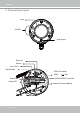
VIVOTEK 3. Hardware Installation 1. Attach the alignment sticker to the wall. Drill four holes into the wall. Then hammer the supplied plastic anchors into the holes and secure the plate with supplied screws. 2. Fix the intersection bracket to the side of the Network Camera with two screws. 3. Feed the RJ45 cable through the front opening of the wall mount bracket. (If you want to use external devices such as sensors and alarms, please refer to the assembling steps on the next page.) 4.
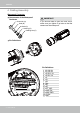
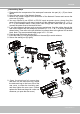
VIVOTEK 4. Cabling Assembly Waterproof Connector Components of the Waterproof Connector Screw Nut (A) Seal (B) Seals (C) Housing (D) IMPORTANT: If you should need to open the front cover, make sure you tighten it up later so that the camera can be waterproof.
VIVOTEK Assembling Steps 1. Disassemble the components of the waterproof connector into part (A) ~ (E) as shown above. 2. Open the rear cover of the Network Camera. 3. Remove the rubber stopper from the bottom of the Network Camera and secure the screw nut (A) tightly. 4. You may choose to use AC24V or DC12V inputs as power source, please feed the power lines through the wall mount bracket and the waterproof connector (E --> D --> B --> A) as illustrated below.
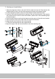
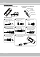
VIVOTEK RJ45 Cable Connector Components of the Waterproof Connector RJ45 Cable Dimension (unit: mm) Sealing Nut (A) Seal (B) Screw Nut (C) Housing (D) Gasket (E) Assembling Steps 1 Prepare an Ethernet cable and strip part of the sheath. 2 Insert the housing into the screw nut. (C) 3 (D) Insert the seal into the housing. (B) Recommended cable gauge: O.D. 5.5~7 4 Insert the stripped Ethernet cable through the sealing nut and the housing. 5 Clamp the cable with an RJ45 plug.
VIVOTEK 5. Network Deployment Power over Ethernet (PoE) When using a PoE-enabled switch The Network Camera is PoE-compliant, allowing transmission of power and data via a single Ethernet cable. Follow the below illustration to connect the Network Camera to a PoE-enabled switch via Ethernet cable. PoE Switch POWER COLLISION 1 2 3 4 5 LINK RECEIVE PARTITION When using a non-PoE switch Use a PoE power injector (optional) to connect between the Network Camera and a non-PoE switch.
VIVOTEK Status LED The LED indicates the status of the Network Camera. Item LED status Green and Red lit for once, and then turn steady red 1 Red LED off 2 Steady Red and Green blinking every 1 sec. Steady Red and Green LED is off Red blinking every 0.15 sec., and Green LED blinking 3 every 1 sec. Red blinking every 0.15 sec. and Green LED blinking 4 every 0.15 sec.
VIVOTEK DI/DO Diagram Please refer to the following illustration for the connection method. GND GND VDC Camera Power Camera Power Input BJT transistor Switch +12 VDC Max.
VIVOTEK Hardware Reset Reset Button The reset button is used to reset the system or restore the factory default settings. Sometimes resetting the system can return the camera to normal operation. If the system problems remain after reset, restore the factory settings and install again. Reset: Press and release the recessed reset button with a straightened paper clip. Wait for the Network Camera to reboot. Restore: Press and hold the recessed reset button until the status LED rapidly blinks.
VIVOTEK Internet connection via a router Before setting up the Network Camera over the Internet, make sure you have a router and follow the steps below. 1. Connect your Network Camera behind a router, the Internet environment is illustrated below. Regarding how to obtain your IP address, please refer to Software Installation on page 17 for details. IP address : 192.168.0.3 WAN (Wide Area Network ) Internet Router IP address : from ISP POWER COLLISION 1 2 3 4 5 Subnet mask : 255.255.255.
VIVOTEK Configure the router, virtual server or firewall, so that the router can forward any data coming into a preconfigured port number to a network camera on the private network, and allow data from the camera to be transmitted to the outside of the network over the same path. From Forward to 122.146.57.120:8000 192.168.2.10:80 122.146.57.120:8001 192.168.2.11:80 ... ... When properly configured, you can access a camera behind the router using the HTTP request as follows: http://122.146.57.
VIVOTEK Software Installation Installation Wizard 2 (IW2), free-bundled software included on the product CD, helps you set up your Network Camera on the LAN. IW2 1. Install IW2 under the Software Utility directory from the software CD. Double-click the IW2 shortcut on your desktop to launch the program. Installation Wizard 2 2. The program will conduct an analysis of your network environment. After your network environment is analyzed, please click Next to continue the program. 3.
VIVOTEK Ready to Use 1. A browser session with the Network Camera should prompt as shown below. 2. You should be able to see live video from your camera. You may also install the 32-channel recording software from the software CD in a deployment consisting of multiple cameras. For its installation details, please refer to its related documents.
VIVOTEK NOTE: If you want to use the supplied sun shield for outdoor environments, please follow the steps below to install: 1. Tighten the supplied two hex couplers. 2. Attach the supplied sun shield to the Network Camera and slide it to the desired position. 3. Fix the sun shield with the supplied two screws. 2 1 3 Accessories VIVOTEK also provides other accessories for versatile applications as the following illustrations. Please visit VIVOTEK's official website for more purchase information.
VIVOTEK Accessing the Network Camera This chapter explains how to access the Network Camera through web browsers, RTSP players, 3GPP-compatible mobile devices, and VIVOTEK recording software. Using Web Browsers Use Installation Wizard 2 (IW2) to access the Network Cameras on LAN. If your network environment is not a LAN, follow these steps to access the Netwotk Camera: 1. Launch your web browser (ex. Microsoft® Internet Explorer, Mozilla Firefox, or Google Chrome). 2.
VIVOTEK ► By default, the Network Camera is not password-protected. To prevent unauthorized access, it is highly recommended to set a password for the Network Camera. For more information about how to enable password protection, please refer to Security on page 81. ► If you see a dialog box indicating that your security settings prohibit running ActiveX ® Controls, please enable the ActiveX ® Controls for your browser. 1. Choose Tools > Internet Options > Security > Custom Level. 2.
VIVOTEK IMPORTANT: 1. Currently the Network Camera utilizes 32-bit ActiveX plugin. You CAN NOT open a management/view session with the camera using a 64-bit IE browser. 2. If you encounter this problem, try execute the Iexplore.exe program from C:\Windows\ SysWOW64. A 32-bit version of IE browser will be installed. 3. On Windows 7, the 32-bit explorer browser can be accessed from here: C:\Program Files (x86)\Internet Explorer\iexplore.exe NOTE: 1.
VIVOTEK Using RTSP Players To view the MPEG-4 streaming media using RTSP players, you can use one of the following players that support RTSP streaming. Quick Time Player VLC Player VLC media player 1. Launch the RTSP player. mpegable Player 2. Choose File > Open URL. A URL dialog box will pop up. 3.
VIVOTEK Using 3GPP-compatible Mobile Devices To view the streaming media through 3GPP-compatible mobile devices, make sure the Network Camera can be accessed over the Internet. For more information on how to set up the Network Camera over the Internet, please refer to Setup the Network Camera over the Internet on page 15. To utilize this feature, please check the following settings on your Network Camera: 1.
VIVOTEK Using VIVOTEK Recording Software The product software CD also contains an ST-7501 recording software, allowing simultaneous monitoring and video recording for multiple Network Cameras. Please install the recording software; then launch the program to add the Network Camera to the Channel list. For detailed information about how to use the recording software, please refer to the user’s manual of the software or download it from http://www.vivotek.com.
VIVOTEK Main Page This chapter explains the layout of the main page. It is composed of the following sections: VIVOTEK INC. Logo, Host Name, Camera Control Area, Configuration Area, Menu, and Live Video Window. VIVOTEK INC. Logo Resize Buttons Host Name Configuration Area Camera Control Area Live View Window Hide Button VIVOTEK INC. Logo Click this logo to visit the VIVOTEK website. Host Name The host name can be customized to fit your needs. For more information, please refer to System on page 36.
VIVOTEK Global View: Click on this item to display the Global View window. The Global View window contains a full view image (the largest frame size of the captured video) and a floating frame (the viewing region of the current video stream). The floating frame allows users to control the e-PTZ function (Electronic Pan/ Tilt/Zoom). For more information about e-PTZ operation, please refer to E-PTZ Operation on page 94.
VIVOTEK H.264 / MPEG-4 Protocol and Media Options Video Title Title and Time Zoom Indicator Video (TPC-AV) 2013/10/25 17:08:56 Time Video 17:08:56 2013/10/25 x4.0 Video and Audio Control Buttons Video Title: The video title can be configured. For more information, please refer to Video Settings on page 48. H.264 / MPEG-4 Protocol and Media Options: The transmission protocol and media options for H.264 / MPEG-4 video streaming. For further configuration, please refer to Client Settings on page 31.
VIVOTEK Video and Audio Control Buttons: Depending on the Network Camera model and Network Camera configuration, some buttons may not be available. Snapshot: Click this button to capture and save still images. The captured images will be displayed in a pop-up window. Right-click the image and choose Save Picture As to save it in JPEG (*.jpg) or BMP (*.bmp) format. Digital Zoom: Click and uncheck “Disable digital zoom” to enable the zoom operation.
VIVOTEK ■ The following window is displayed when the video mode is set to MJPEG: Video Title Title and Time Video (HTTP-V) 2013/10/25 17:08:56 Time Video 17:08:56 2013/10/25 Video Control Buttons Video Title: The video title can be configured. For more information, please refer to Media > Image on page 48. Time: Display the current time. For more information, please refer to Media > Image on page 48. Title and Time: Video title and time can be stamped on the streaming video.
VIVOTEK Client Settings This chapter explains how to select the stream transmission mode and saving options on the local computer. When completed with the settings on this page, click Save on the page bottom to enable the settings. H.264 Media Options H.264 Media Options Select to stream video or audio data or both. This is enabled only when the video mode is set to H.264 or MPEG-4. H.264 Protocol Options H.
VIVOTEK Two way audio Half duplex: Audio is transmitted from one direction at a time, e.g., from a PC holding a web console with the camera. Full duplex: Audio is transmitted in both directions simultaneously. MP4 Saving Options Users can record live video as they are watching it by clicking page. Here, you can specify the storage destination and file name. Start MP4 Recording on the main Folder: Specify a storage destination for the recorded video files.
VIVOTEK Joystick Settings Enable Joystick Connect to the USB plug of the joystick to a USB port on your management computer. Supported by the plug-in in the main page (Microsoft’s DirectX), once the plug-in in the main page is loaded, it will automatically detect if there is any joystick on the computer. The joystick should work properly without installing any other driver or software. Then you can begin to configure the joystick settings of connected devices.
VIVOTEK Buttons Configuration Click the Configure Buttons button, a window will prompt as shown below. Please follow the steps below to configure your joystick buttons: 1. Select a button number from the Button # pull-down menu. Tips If you are not sure of the locations of each button, use the Properties window in the Game Controllers utility. 2. Select a corresponding action, such as Patrol or Preset#. 3. Click the Assign button to assign an action to the button.
VIVOTEK Configuration Click Configuration on the main page to enter the camera setting pages. Note that only Administrators can access the configuration page. VIVOTEK offers an easy-to-use user interface that helps you set up your network camera with minimal effort. In order to simplify the user interface, the detailed information will be hidden unless you click on the function item.
VIVOTEK System > General settings This section explains how to configure the basic settings for the Network Camera, such as the host name and system time. It is composed of the following two columns: System, and System Time. When finished with the settings on this page, click Save at the bottom of the page to enable the settings. System Host name: Enter a desired name for the Network Camera.
VIVOTEK System time Keep current date and time: Select this option to preserve the current date and time of the Network Camera. The Network Camera’s internal real-time clock maintains the date and time even when the power of the system is turned off. Synchronize with computer time: Select this option to synchronize the date and time of the Network Camera with the local computer. The read-only date and time of the PC is displayed as updated. Manual: The administrator can enter the date and time manually.
VIVOTEK System > Homepage layout This section explains how to set up your own customized homepage layout. General settings This column shows the settings of your hompage layout. You can manually select the background and font colors in Theme Options (the second tab on this page). The settings will be displayed automatically in this Preview field. The following shows the homepage using the default settings: ■ Hide Powered by VIVOTEK: If you check this item, it will be removed from the homepage.
VIVOTEK Theme Options Here you can change the color of your homepage layout. There are three types of preset patterns for you to choose from. The new layout will simultaneously appear in the Preview filed. Click Save to enable the settings.
VIVOTEK ■ Follow the steps below to set up the customed homepage: 1. Click Custom on the left column. 2. Click the field where you want to change the color on the right column. Color Selector Custom Pattern 3. The palette window will pop up as shown below. 2 3 1 4 4. Drag the slider bar and click on the left square to select a desired color. 5. The selected color will be displayed in the corresponding fields and in the Preview column. 6. Click Save to enable the settings.
VIVOTEK System > Logs This section explains how to configure the Network Camera to send the system log to a remote server as backup. Log server settings Follow the steps below to set up the remote log: 1. Select Enable remote log. 2. In the IP address text box, enter the IP address of the remote server. 2. In the port text box, enter the port number of the remote server. 3. When completed, click Save to enable the setting.
VIVOTEK You can install the included ST7501 recording software, which provides an Event Management function group for delivering event messages via emails, GSM short messages, onscreen event panel, or to trigger an alarm, etc. For more information, refer to the ST7501 User Manual.
VIVOTEK Access log Access log displays the access time and IP address of all viewers (including operators and administrators) in a chronological order. The access log is stored in the Network Camera’s buffer area and will be overwritten when reaching a certain limit. System > Parameters The View Parameters page lists the entire system’s parameters. If you need technical assistance, please provide the information listed on this page.
VIVOTEK System > Maintenance This chapter explains how to restore the Network Camera to factory default, upgrade firmware version, etc. General settings > Upgrade firmware This feature allows you to upgrade the firmware of your Network Camera. It takes a few minutes to complete the process. Note: Do not power off the Network Camera during the upgrade! Follow the steps below to upgrade the firmware: 1. Download the latest firmware file from the VIVOTEK website. The file is in .pkg file format. 2.
VIVOTEK General settings > Restore This feature allows you to restore the Network Camera to factory default settings. Network: Select this option to retain the Network Type settings (please refer to Network Type on page 63). Daylight Saving Time: Select this option to retain the Daylight Saving Time settings (please refer to Import/Export files below on this page). Custom Language: Select this option to retain the Custom Language settings.
VIVOTEK 3. Open the file with Microsoft® Notepad and locate your time zone; set the start and end time of DST. When completed, save the file. In the example below, DST begins each year at 2:00 a.m. on the second Sunday in March and ends at 2:00 a.m. on the first Sunday in November. Update daylight saving time rules: Click Browse… and specify the XML file to update. If the incorrect date and time are assigned, you will see the following warning message when uploading the file to the Network Camera.
VIVOTEK The following message is displayed when attempting to upload an incorrect file format. Export language file: Click to export language strings. VIVOTEK provides nine languages: English, Deutsch, Español, Français, Italiano, 日本語, Português, 簡体中文, and 繁體中文. Update custom language file: Click Browse… and specify your own custom language file to upload. Export configuration file: Click to export all parameters for the device and user-defined scripts.
VIVOTEK Media > Image This section explains how to configure the image settings of the Network Camera. It is composed of the following five columns: General settings, Image settings, Exposure, Focus, and Privacy mask. General settings Video title Show_timestamp_and video_title_in_video_and_snapshots: Enter a name that will be displayed on the title bar of the live video as shown below.
VIVOTEK Power line frequency: Set the power line frequency consistent with local utility settings to eliminate image flickering associated with fluorescent lights. Note that after the power line frequency is changed, you must disconnect and reconnect the power cord of the Network Camera in order for the new setting to take effect. Video orientation: Flip - vertically reflect the display of the live video; Mirror - horizontally reflect the display of the live video.
VIVOTEK Image settings On this page, you can tune the White balance and Image adjustment. Sensor Setting 1: For normal situations Sensor Setting 2: For special situations White balance: Adjust the value for the best color temperature. ■ You may follow the steps below to adjust the white balance to the best color temperature. 1. Place a sheet of paper of white or cooler-color temperature color, such as blue, in front of the lens, then allow the Network Camera to automatically adjust the color temperature.
VIVOTEK Enable 3D Noise reduction ■ Check to enable noise reduction in order to reduce noises and flickers in image. This applies to the onboard 3D Noise Reduction feature. Use the pull-down menu to adjust the reduction strength. Note that applying this function to the video channel will consume system computing power. 3D Noise Reduction is mostly applied in low-light conditions. When enabled in a low-light condition with fast moving objects, trails of after-images may occur.
VIVOTEK IMPORTANT: 1. When the WDR Pro function is enabled, you cannot enter the Exposure > Manual mode window to configure a measurement window. 2. When in the Exposure > Manual setting page, you can configure up to 10 Inclusive measurement windows. There are no Exclusive measurement windows. 3. When the WDR Pro function is enabled or disabled, the configuration live view will be temporarily disabled for 8 to 10 seconds. 4.
VIVOTEK Exposure control: ■ Exposure level: You can manually set the Exposure level, which ranges from -2.0 to +2.0 (dark to bright). You can click and drag the pointers on the Exposure time and Gain control slide bars to specify a range of shutter time and Gain control values within which the camera can automatically tune to an optimal imaging result.
VIVOTEK If you want to configure another sensor setting for day/night/schedule mode, please click Profile to open the Profile of exposure settings page as shown below. Activated period: Select the mode this profile to apply to the Schedule mode. Please manually enter a range of time if you choose Schedule mode. Then check Save to take effect. Please follow the steps below to setup a profile: 1. Check Enable this profile. 2. Select the applied mode: Day mode, Night mode, or Schedule mode.
VIVOTEK Focus Focus, also known as Remote Focus, is applicable to Network Cameras that are equipped with stepping motor lens. The automated focus adjustment function eliminates the needs to physically adjust camera focus. In an outdoor deployment consisting of a large number of cameras, the auto focus function can be very helpful when these cameras become out of focus after days or weeks of operation. And that can easily result from the effects of natural forces, e.g.
VIVOTEK Auto Focus: Click the Perform auto focus button for the camera to automatically find the best focus. The process takes about 20 seconds to complete. The Focus pointer will stay at the optimal location on the slide bar. You may still need to use the arrow marks to fine-tune the focus depending on the live image on your screen. “>” means moving from wide to tele end; and “<” tele to wide. ■ Full-range scan: If selected, the auto focus scan will be performed throughout the complete range of focus.
VIVOTEK Privacy mask Click Privacy Mask to open the settings page. On this page, you can block out sensitive zones to address privacy concerns. 2013/11/09 17:08:56 ■ To set the privacy mask windows, follow the steps below: 1. Click New to add a new window. 2. You can use the mouse cursor to size and drag-drop the window, which is recommended to be at least twice the size of the object (height and width) you want to cover. 3. Enter a Window Name and click Save to enable the setting. 4.
VIVOTEK Media > Video Stream settings This Network Camera supports multiple streams with frame sizes ranging from 176 x 144 to 1280 x 1024 (IP8355EH) - or 176 x 144 to 1920 x1080 (IP8365EH). The definition of multiple streams: ■ Stream 1: The default frame size for Stream 1 is set to the 1280 x 1024 at 30fps. ■ Stream 2: The default frame size for Stream 2 is set to the 640 x 480 at 15fps. IMPORTANT: 1.
VIVOTEK Click the stream item to display the detailed information. The maximum frame size will follow your settings in the above Viewing Window sections. This Network Camera offers real-time H.264 and MJPEG compression standards (Dual Codec) for real-time viewing. If the H.264 mode is selected, the video is streamed via RTSP protocol. There are several parameters through which you can adjust the video performance: ■ Frame size You can set up different video resolutions for different viewing devices.
VIVOTEK ■ Intra frame period Determine how often for firmware to plant an I frame. The shorter the duration, the more likely you will get better video quality, but at the cost of higher network bandwidth consumption. Select the intra frame period from the following durations: 1/4 second, 1/2 second, 1 second, 2 seconds, 3 seconds, and 4 seconds. ■ Video quality • Constant bit rate: A complex scene generally produces a larger file size, meaning that higher bandwidth will be needed for data transmission.
VIVOTEK If JPEG mode is selected, the Network Camera sends consecutive JPEG images to the client, producing a moving effect similar to a filmstrip. Every single JPEG image transmitted guarantees the same image quality, which in turn comes at the expense of variable bandwidth usage. Because the media contents are a combination of JPEG images, no audio data is transmitted to the client.
VIVOTEK Media > Audio Audio Settings Mute: Select this option to disable audio transmission from the Network Camera to all clients. Note that if muted, no audio data will be transmitted even if audio transmission is enabled on the Client Settings page. In that case, the following message is displayed: External microphone input gain: Select the gain of the external audio input according to ambient conditions. Adjust the gain from 100% (most sensitive) to 0% (least sensitive).
VIVOTEK Network > General settings This section explains how to configure a wired network connection for the Network Camera. Network Type LAN Select this option when the Network Camera is deployed on a local area network (LAN) and is intended to be accessed by local computers. The default setting for the Network Type is LAN. Please rememer to click on the Save button when you complete the Network setting.
VIVOTEK Primary DNS: The primary domain name server that translates hostnames into IP addresses. Secondary DNS: Secondary domain name server that backups the Primary DNS. Primary WINS server: The primary WINS server that maintains the database of computer names and IP addresses. Secondary WINS server: The secondary WINS server that maintains the database of computer names and IP addresses.
VIVOTEK NOTE: ► If the default ports are already used by other devices connected to the same router, the Network Camera will select other ports for the Network Camera. ► If UPnP TM is not supported by your router, you will see the following message: Error: Router does not support UPnP port forwarding. ► Steps to enable the UPnP TM user interface on your computer: Note that you must log on to the computer as a system administrator to install the UPnP TM components. 1.
VIVOTEK 4. In the Networking Services dialog box, select Universal Plug and Play and click OK. 5. Click Next in the following window. 6. Click Finish. UPnP TM is enabled. ► How does UPnP TM work? UPnP TM networking technology provides automatic IP configuration and dynamic discovery of devices added to a network. Services and capabilities offered by networked devices, such as printing and file sharing, are available among each other without the need for cumbersome network configuration.
VIVOTEK Enable IPv6 Select the Enable IPv6 checkbox and click Save to enable IPv6 settings. Please note that this only works if your network environment and hardware equipment support IPv6. The browser should be Microsoft® Internet Explorer 7 or 8, Mozilla Firefox 13.0 or above. When IPv6 is enabled, by default, the network camera will listen to router advertisements and be assigned with a link-local IPv6 address accordingly.
VIVOTEK Please follow the steps below to link to an IPv6 address: 1. Open your web browser. 2. Enter the link-global or link-local IPv6 address in the address bar of your web browser. 3. The format should be: http://[2001:0c08:2500:0002:0202:d1ff:fe04:65f4]/ IPv6 address 4. Press Enter on the keyboard or click Refresh button to refresh the webpage.
VIVOTEK Port HTTPS port: By default, the HTTPS port is set to 443. It can also be assigned to another port number between 1025 and 65535. Two way audio port: By default, the two way audio port is set to 5060. Also, it can also be assigned to another port number between 1025 and 65535. The Network Camera supports two way audio communication so that operators can transmit and receive audio simultaneously.
VIVOTEK Audio is being transmitted to the Network Camera 2013/06/09 17:08:56 Mute Talk Button Mic Volume Click to enable audio transmission to the Network Camera; click to adjust the volume of to turn off the audio. To stop talking, click again. microphone; click FTP port: The FTP server allows the user to save recorded video clips. You can utilize VIVOTEK's Installation Wizard 2 to upgrade the firmware via FTP server. By default, the FTP port is set to 21.
VIVOTEK Network > Streaming protocols HTTP streaming To utilize HTTP authentication, make sure that your have set a password for the Network Camera first; please refer to Security > User account on page 81 for details. Authentication: Depending on your network security requirements, the Network Camera provides two types of security settings for an HTTP transaction: basic and digest.
VIVOTEK URL command -- http://:/ For example, when the Access name for stream 2 is set to video2.mjpg: 1. Launch Mozilla Firefox or Netscape. 2. Type the above URL command in the address bar. Press Enter. 3. The JPEG images will be displayed in your web browser. http://192.168.5.151/video2.
VIVOTEK Authentication: Depending on your network security requirements, the Network Camera provides three types of security settings for streaming via RTSP protocol: disable, basic, and digest. If basic authentication is selected, the password is sent in plain text format, but there can be potential risks of it being intercepted. If digest authentication is selected, user credentials are encrypted using MD5 algorithm, thus providing better protection against unauthorized access.
VIVOTEK Multicast settings for stream 1 ~ 2: Click the items to display the detailed configuration information. Select the Always multicast option to enable multicast for stream 1 ~ 2. Unicast video transmission delivers a stream through point-to-point transmission; multicast, on the other hand, sends a stream to the multicast group address and allows multiple clients to acquire the stream at the same time by requesting a copy from the multicast group address.
VIVOTEK Network > DDNS This section explains how to configure the dynamic domain name service for the Network Camera. DDNS is a service that allows your Network Camera, especially when assigned with a dynamic IP address, to have a fixed host and domain name. Express link Express Link is a free service provided by VIVOTEK server, which allows users to register a domain name for a network device. One URL can only be mapped to one MAC address.
VIVOTEK Manual setup DDNS: Dynamic domain name service Enable DDNS: Select this option to enable the DDNS setting. Provider: Select a DDNS provider from the provider drop-down list. VIVOTEK offers Safe100.net, a free dynamic domain name service, to VIVOTEK customers. It is recommended that you register Safe100.net to access VIVOTEK’s Network Cameras from the Internet. Additionally, we offer other DDNS providers, such as Dyndns.org(Dynamic), Dyndns. org(Custom), CustomSafe100, and dyn-interfree.it.
VIVOTEK [Register] Successfully Your account information has been mailed to registered e-mail address 4. Select Enable DDNS and click Save to enable the setting. ■ CustomSafe100 VIVOTEK offers documents to establish a CustomSafe100 DDNS server for distributors and system integrators. You can use CustomSafe100 to register a dynamic domain name if your distributor or system integrators offer such services. 1. In the DDNS column, select CustomSafe100 from the drop-down list. 2.
VIVOTEK Network > QoS (Quality of Service) Quality of Service refers to a resource reservation control mechanism, which guarantees a certain quality to different services on the network. Quality of service guarantees are important if the network capacity is insufficient, especially for real-time streaming multimedia applications. Quality can be defined as, for instance, a maintained level of bit rate, low latency, no packet dropping, etc.
VIVOTEK QoS/DSCP (the DiffServ model) DSCP-ECN defines QoS at Layer 3 (Network Layer). The Differentiated Services (DiffServ) model is based on packet marking and router queuing disciplines. The marking is done by adding a field to the IP header, called the DSCP (Differentiated Services Codepoint). This is a 6-bit field that provides 64 different class IDs. It gives an indication of how a given packet is to be forwarded, known as the Per Hop Behavior (PHB).
VIVOTEK Network > SNMP (Simple Network Management Protocol) This section explains how to use the SNMP on the network camera. The Simple Network Management Protocol is an application layer protocol that facilitates the exchange of management information between network devices. It helps network administrators to remotely manage network devices and find, solve network problems with ease. ■ The SNMP consists of the following three key components: 1.
VIVOTEK Security > User Account This section explains how to enable password protection and create multiple accounts. Root Password The administrator account name is “root”, which is permanent and can not be deleted. If you want to add more accounts in the Manage User column, please apply the password for the “root” account first. 1. Type the password identically in both text boxes, then click Save to enable password protection. 2.
VIVOTEK Security > HTTPS (Hypertext Transfer Protocol over SSL) This section explains how to enable authentication and encrypted communication over SSL (Secure Socket Layer). It helps protect streaming data transmission over the Internet on higher security level. Create and Install Certificate Method Before using HTTPS for communication with the Network Camera, a Certificate must be created first. There are three ways to create and install a certificate: Create self-signed certificate 1.
VIVOTEK 5. Click Save to preserve your configuration, and your current session with the camera will change to the encrypted connection. 6. If your web session does not automatically change to an encrypted HTTPS session, click Home to return to the main page. Change the URL address from “http://” to “https://“ in the address bar and press Enter on your keyboard. Some Security Alert dialogs will pop up. Click OK or Yes to enable HTTPS. https:// https://192.168.5.151/index.
VIVOTEK Create certificate request and install 1. Select the option from the Method pull-down menu. 2. Click Create certificate to proceed. 3. The following information will show up in a pop-up window after clicking Create. Then click Save to generate the certificate request. 4. The Certificate request window will prompt. If you see the following Information bar, click OK and click on the Information bar at the top of the page to allow pop-ups.
VIVOTEK 5. Look for a trusted certificate authority, such as Symantec’s VeriSign Authentication Services, that issues digital certificates. Sign in and purchase the SSL certification service. Copy the certificate request from your request prompt and paste it in the CA’s signing request window. Proceed with the rest of the process as CA’s instructions on their webpage. 6. Once completed, your SSL certificate should be delivered to you via an email or other means.
VIVOTEK 7. Open a new edit, paste the certificate contents, and press ENTER at the end of the contents to add an empty line. 8. Convert file format from DOS to UNIX. Open File menu > Conversions > DOS to Unix.
VIVOTEK 9. Save the edit using the “.crt” extension, using a file name like “CAcert.crt.” 10. Return to the original firmware session, use the Browse button to locate the crt certificate file, and click Upload to enable the certification.
VIVOTEK 11. When the certifice file is successfully loaded, its status will be stated as Active. Note that a certificate must have been created and installed before you can click on the “Save" button for the configuration to take effect. 12.To begin an encrypted HTTPS session, click Home to return to the main page. Change the URL address from “http://” to “https://“ in the address bar and press Enter on your keyboard. Some Security Alert dialogs will pop up. Click OK or Yes to enable HTTPS.
VIVOTEK Security > Access List This section explains how to control access permission by verifying the client PC’s IP address. General Settings Maximum number of concurrent streaming connection(s) limited to: Simultaneous live viewing for 1~10 clients (including stream 1 and stream 2). The default value is 10. If you modify the value and click Save, all current connections will be disconnected and automatically attempt to re-link (IE Explore or Quick Time Player).
VIVOTEK ■ Refresh: Click this button to refresh all current connections. ■ Add to deny list: You can select entries from the Connection Status list and add them to the Deny List to deny access. Please note that those checked connections will only be disconnected temporarily and will automatically try to re-link again (IE Explore or Quick Time Player). If you want to enable the denied list, please check Enable access list filtering and click Save in the first column.
VIVOTEK There are three types of rules: Single: This rule allows the user to add an IP address to the Allowed/Denied list. For example: 192.168.2.1 Network: This rule allows the user to assign a network address and corresponding subnet mask to the Allow/Deny List. The address and network mask are written in CIDR format. For example: IP address 192.168.2.x will be bolcked. If IPv6 filter is preferred, you will be prompted by the following window.
VIVOTEK Security > IEEE 802.1X Enable this function if your network environment uses IEEE 802.1x, which is a port-based network access control. The network devices, intermediary switch/access point/hub, and RADIUS server must support and enable 802.1x settings. The 802.1x standard is designed to enhance the security of local area networks, which provides authentication to network devices (clients) attached to a network port (wired or wireless).
VIVOTEK 3. When all settings are complete, move the Network Camera to the protected LAN by connecting it to an 802.1x enabled switch. The devices will then start the authentication automatically. NOTE: ► The authentication process for 802.1x: 1. The Certificate Authority (CA) provides the required signed certificates to the Network Camera (the supplicant) and the RADIUS Server (the authentication server). 2. A Network Camera requests access to the protected LAN using 802.
VIVOTEK PTZ > PTZ settings This section explains how to control the Network Camera’s Pan/Tilt/Zoom operation. The e-PTZ fucntion allows users to quickly move the focus to a target area for close-up viewing without physically moving the camera. Please refer to below for detailed instruction.
VIVOTEK Select Stream: Select stream #1 to set up the e-PTZ control. Please note that each stream can possess its own preset and patrol settings. For detailed information about how to set up preset and patrol settings, please refer to page 94. Auto pan/patrol speed: Select the speed from 1~5 (slow/fast) to set up the Auto pan/patrol speed control. When completed with the e-PTZ settings, click Save to enable the settings on this page. Home page in E-PTZ Mode x3.
VIVOTEK Patrol settings You can select some preset positions for the Network Camera to patrol. Please follow the steps below to set up a patrol schedule: 1. Select the preset locations on the list, and click . 2. The selected preset locations will be displayed on the Patrol locations list. 3. Set the Dwelling time for the preset location during auto patrol. 4. If you want to delete a preset location from the Patrol locations list, select it and click Remove. 5.
VIVOTEK Home page in the e-PTZ Mode The Preset positions will also be displayed on the home page. Select one from the Go to drop-down list, and the Network Camera will move to the selected preset position. Patrol button: Click this button, then the Network Camera will patrol among the selected preset positions continuously. NOTE NOTE: ► The Preset Positions will also be displayed on the home page. Select one from the Go to drop-down list, and the Network Camera will move to the selected preset position.
VIVOTEK Event > Event settings This section explains how to configure the Network Camera to responds to particular situations (event). A typical application is that when a motion is detected, the Network Camera sends buffered images to an FTP server or e-mail address as notifications. Click on Help, there is an illustration shown in the pop-up window explaining that an event can be triggered by many sources, such as motion detection or external digital input devices.
VIVOTEK ■ Event name: Enter a name for the event setting. ■ Enable this event: Select this option to enable the event setting. ■ Priority: Select the relative importance of this event (High, Normal, or Low). Events with a higher priority setting will be executed first. seconds: Enter the duration in seconds to pause ■ Detect next motion detection or digital input after motion detection after a motion is detected. This can prevent event-related actions to be too frequently performed. 1.
VIVOTEK ■ Audio detection A preset threshold can be configured with an external microphone as the trigger to system event. The triggering condition can be an input exceeding or falling below a threshold. Audio detection can take place as a complement to motion detection or as a method to detect activities not covered by the camera's view. Once you have a preset audio alarm level, you can define the triggering condition either as an audio input rises above or falls below the alarm level.
VIVOTEK 3. Action Define the actions to be performed by the Network Camera when a trigger is activated. ■ Trigger digital output for seconds Select this option to turn on the external digital output device when a trigger is activated. Specify the length of the trigger interval in the text box. ■ Backup media if the network is disconnected Select this option to backup media file on SD card if the network is disconnected. This function will only be displayed after you set up a networked storage (NAS).
VIVOTEK Add server To set an event with recorded video or snapshots, it is necessary to configure the server and media settings so that the Network Camera will know what action to take (such as which server to send the media files to) when a trigger is activated. Click Add server to open the server setting window. You can specify where the notification messages are sent when a trigger is activated. A total of 5 server settings can be configured.
VIVOTEK To verify if the email settings are correctly configured, click Test. The result will be shown in a pop-up window. If successful, you will also receive an email indicating the result. Click Save server to enable the settings. Note that after you set up the first event server, the new event server will automatically display on the Server list. If you wish to add other server options, click Add server. Server type - FTP Select to send the media files to an FTP server when a trigger is activated.
VIVOTEK ■ Passive mode Most firewalls do not accept new connections initiated from external requests. If the FTP server supports passive mode, select this option to enable passive mode FTP and allow data transmission to pass through the firewall. The firmware default has the Passive mode checkbox selected. To verify if the FTP settings are correctly configured, click Test. The result will be shown in a pop-up window as shown below. If successful, you will also receive a test.txt file on the FTP server.
VIVOTEK Network storage: Select to send the media files to a network storage location when a trigger is activated. Please refer to NAS server on page 122 for details. Click Save server to enable the settings. ■ SD Test: Click to test your SD card. The system will display a message indicating success or failure. If you want to use your SD card for local storage, please format it before use. Please refer to page 125 for detailed information. ■ View: Click this button to open a file list window.
VIVOTEK Click 20130220 to open the directory: The format is: HH (24r) Click to open the file list for that hour 2013/02/20 2013/02/20 Click to go back to the previous level of the directory Click to delete selected items Click to delete all recorded data 2013/02/20 2013/02/20 The format is: File name prefix + Minute (mm) You can set up the file name prefix on Add media page. Please refer to next page for detailed information.
VIVOTEK Add media Click Add media to open the media setting window. You can specify the type of media that will be sent when a trigger is activated. A total of 5 media settings can be configured. There are three choices of media types available: Snapshot, Video Clip, and System log. Select the item to display the detailed configuration options. You can configure either one or all of them. Media type - Snapshot Select to send snapshots when a trigger is activated.
VIVOTEK ■ Add date and time suffix to the file name Select this option to add a date/time suffix to the file name. For example: Snapshot_20130713_100341 File name prefix Date and time suffix The format is: YYYYMMDD_HHMMSS Click Save media to enable the settings. To note that after you set up the first media server, a new column for media server will automatically show up on the Media list. If you wish to add more other media options, click Add media.
VIVOTEK ■ Maximum file size Specify the maximum file size allowed. ■ File name prefix Enter the text that will be appended to the front of the file name. For example: Video_20130813_100341 File name prefix Date and time suffix The format is: YYYYMMDD_HHMMSS Click Save media to enable the settings. Media type - System log Select to send a system log when a trigger is activated. Click Save media to enable the settings, then click Close to exit the page.
VIVOTEK In the Event settings column, the Servers and Medias you configured will be listed; please make sure the Event -> Status is indicated as ON, in order to enable the event triggering action. When completed, click Save event to enable the settings and click Close to exit Event Settings page. The new Event / Server settings / Media will appear in the event drop-down list on the Event setting page.
VIVOTEK Customized Script This function allows you to upload a sample script (.xml file) to the webpage, which will save your time on configuring the settings. Please note that there is a limited number of customized scripts you can upload; if the current amount of customized scripts has reached the limit, an alert message will prompt. If you need more information, please contact VIVOTEK technical support.
VIVOTEK Applications > Motion detection This section explains how to configure the Network Camera to enable motion detection. A total of three motion detection windows can be configured. 2010/12/10 17:08:56 2013/11/5 14:39:12 Motion Detection Setting 1: For normal situations Follow the steps below to enable motion detection: Follow the steps below to enable motion detection: Motion Detection Setting 2: For special situations 1. Click New to add a new motion detection window. 2.
VIVOTEK A green bar indicates that even though motions have been detected, the event has not been triggered because the image variations still fall under the defined threshold. Percentage = 30% If you want to configure other motion detection settings for day/night/schedule mode, please click Profile to open the Motion Detection Profile Settings page as shown below. A total of three motion detection windows can be configured on this page as well.
VIVOTEK NOTE NOTE: ► How does motion detection work? A C B D There are two motion detection parameters: Sensitivity and Percentage. In the illustration above, frame A and frame B are two sequential images. Pixel differences between the two frames are detected and highlighted in gray (frame C) and will be compared with the sensitivity setting. Sensitivity is a value that expresses the sensitivity to moving objects.
VIVOTEK Applications > DI and DO Connect DI or DO devices to the camera's terminal block, the camera will automatically detect the current connection state as pulled-high or pulled-low. You may then define the triggering condition. Digital input: Select High or Low to define the "active state" for the digital input. The Network Camera will report the current status. Digital output: Select Grounded or Open to define the "active state" for the digital output.
VIVOTEK Applications > Audio detection Audio detection, along with video motion detection, is applicable in the following scenarios: 1. Detection of activities not covered by camera view, e.g., a loud input by gun shots or breaking a door/window. 2. A usually noisy environment, such as a factory, suddenly becomes quiet due to a breakdown of machines. 3. A PTZ camera can be directed to turn to a preset point by the occurrence of audio events. 4.
VIVOTEK You can use the Profile window to configure a different Audio detection setting. For example, a place can be noisy in the day time and become very quiet in the night. 1. Click on the Enable this profile checkbox. Once the Audio detection window is opened, the current sound input will be interactively indicated by a fluctuating yellow wave diagram. 2. Use a mouse click to drag the Alarm level tab to a preferred location on the slide bar. 3. Select the Day, Night, or Schedule mode check circles.
VIVOTEK Applications > VADP (VIVOTEK Application Development Platform) Users can store and execute VIVOTEK's or 3rd-party software modules onto the camera's flash memory or SD card. These software modules can apply in video analysis for intelligent video applications such as license plate recognition, object counting, or as an agent for edge recording, etc. • Once the software package is successfully uploaded, the module configuration (vadp. xml) information is displayed.
VIVOTEK To start a module, select the checkcircle in front, and click the Start button. If you should need to remove a module, select the checkcircle in front and then click the Stop button. By then the module status will become OFF, and the X button will appear at the end of the row. Click on the X button to remove an existing module. When prompted by a confirm message, Click Yes to proceed.
VIVOTEK Recording > Recording settings This section explains how to configure the recording settings for the Network Camera. Recording Settings Insert your SD card and click here to test NOTE NOTE: ► Please remember to format your SD card when using it for the first time. Please refer to page 125 for detailed information. Recording Settings Click Add to open the recording setting window. On this page, you can define the adaptive recording, recording source, recording schedule, and recording capacity.
VIVOTEK If you enable adaptive recording and enable time-shift cache stream on Camera A, only when an event is triggered on Camera A will the server record the full frame rate streaming data; otherwise, it will only request the I frame data during normal monitoring, thus effectively save lots of bandwidths and storage space. NOTE: ► To enable adaptive recording, please make sure you’ve set up the trigger source such as Motion Detection, DI Device, or Manual Trigger.
VIVOTEK 2. Destination You can select the SD card or network storage (NAS) for the recorded video files. NAS server Click Add NAS server to open the server setting window and follow the steps below to set up: 1. Fill in the information for your server. For example: 3 Network storage path (\\server name or IP address\folder name) 1 2 4 User name and password for your server 2. Click Test to check the setting. The result will be shown in the pop-up window.
VIVOTEK If successful, you will receive a test.txt file on the network storage server. 3. Enter a server name. 4. Click Save to complete the settings and click Close to exit the page. ■ Capacity: You can choose either the entire free space available or limit the reserved space. The recording size limit must be larger than the reserved amount for cyclic recording. ■ File name prefix: Enter the text that will be appended to the front of the file name.
VIVOTEK To remove a recording setting from the list, select a recording name from the drop-down list and click Delete. ■ Click Video (Name): Opens the Recording Settings page to modify. ■ Click ON (Status): The Status will become OFF and stop recording. ■ Click NAS (Destination): Opens the file list of recordings as shown below. For more information about folder naming rules, please refer to page 122 for details.
VIVOTEK Local storage > SD card management This section explains how to manage the local storage on the Network Camera. Here you can view SD card status, and implement SD card control. SD card staus This column shows the status and reserved space of your SD card. Please remember to format the SD card when using for the first time. no SD card SD card control ■ Enable cyclic storage: Check this item if you want to enable cyclic recording.
VIVOTEK Local storage > Content management This section explains how to manage the content of recorded videos on the Network Camera. Here you can search and view the records and view the searched results. Searching and Viewing the Records This column allows the user to set up search criteria for recorded data. If you do not select any criteria and click Search button, all recorded data will be listed in the Search Results column. ■ File attributes: Select one or more items as your search criteria.
VIVOTEK Search Results The following is an example of search results. There are four columns: Trigger time, Media type, Trigger type, and Locked. Click to sort the search results in either direction. Numbers of entries displayed on one page Enter a key word to filter the search results Highlight an item ■ View: Click on a search result which will highlight the selected item in purple as shown above. Click the View button and a media window will pop up to play back the selected file.
VIVOTEK ■ Lock/Unlock: Select the desired search results, then click this button. The selected items will become Locked, which will not be deleted during cyclic recording. You can click again to unlock the selections. For example: Click to switch pages ■ Remove: Select the desired search results, then click this button to delete the files.
VIVOTEK Appendix URL Commands for the Network Camera 1. Overview For some customers who already have their own web site or web control application, the Network Camera/Video Server can be easily integrated through URL syntax. This section specifies the external HTTP-based application programming interface. The HTTP-based camera interface provides the functionality to request a single image, control camera functions (PTZ, output relay etc.), and get and set internal parameter values.
VIVOTEK 3. General CGI URL Syntax and Parameters CGI parameters are written in lower-case and as one word without any underscores or other separators. When the CGI request includes internal camera parameters, these parameters must be written exactly as they are named in the camera or video server. The CGIs are organized in functionally-related directories under the cgi-bin directory. The file extension .cgi is required. Syntax: http:///cgi-bin/[/...]/.
VIVOTEK 5. Get Server Parameter Values Note: The access right depends on the URL directory. Method: GET/POST Syntax: http:///cgi-bin/anonymous/getparam.cgi?[] [&…] http:///cgi-bin/viewer/getparam.cgi?[] [&…] http:///cgi-bin/operator/getparam.cgi?[] [&…] http:///cgi-bin/admin/getparam.cgi?[] [&…] Where the should be [_] or [.].
VIVOTEK http://192.168.0.123/cgi-bin/admin/getparam.cgi?network_ipaddress Response: HTTP/1.0 200 OK\r\n Content-Type: text/html\r\n Context-Length: 33\r\n \r\n network.ipaddress=192.168.0.123\r\n 6. Set Server Parameter Values Note: The access right depends on the URL directory. Method: GET/POST Syntax: http:///cgi-bin/anonymous/setparam.cgi? = [&=…][&update=][&return=] http:///cgi-bin/viewer/setparam.
VIVOTEK placed at the end of the parameter list Return: HTTP/1.0 200 OK\r\n Content-Type: text/html\r\n Context-Length: \r\n \r\n where is =\r\n [] Only the parameters that you set and are readable will be returned. Example: Set the IP address of server to 192.168.0.123: Request: http://myserver/cgi-bin/admin/setparam.cgi?network_ipaddress=192.168.0.123 Response: HTTP/1.
VIVOTEK mac address A string limited to contain a MAC address without hyphens or colons. boolean A boolean value of 1 or 0 represents [Yes or No], [True or False], [Enable or Disable]. , Enumeration. Only given values are valid. , , … blank A blank string. everything inside <> A description integer primary key SQLite data type. A 32-bit signed integer. The value is assigned a unique integer by the server. text SQLite data type.
VIVOTEK 7.1 system Group: system NAME VALUE DEFAULT SECURITY DESCRIPTION (get/set) hostname string[64] Mega-Pixel 1/6 Host name of server Network (Network Camera, Camera Wireless Network Camera, Video Server, Wireless Video Server). ledoff 0 6/6 Turn on (0) or turn off (1) all led indicators. date , date> 6/6 Current date of system. Set to ‘keep’ to keep date unchanged. Set to ‘auto’ keep, to use NTP to synchronize date.
VIVOTEK -281: GMT-07:00 Arizona -240: GMT-06:00 Central America, Central Time, Mexico City, Saskatchewan -200: GMT-05:00 Eastern Time, New York, Toronto -201: GMT-05:00 Bogota, Lima, Quito, Indiana -180: GMT-04:30 Caracas -160: GMT-04:00 Atlantic Time, Canada, La Paz, Santiago -140: GMT-03:30 Newfoundland -120: GMT-03:00 Brasilia, Buenos Aires, Georgetown, Greenland -80: GMT-02:00 Mid-Atlantic -40: GMT-01:00 Azores, Cape_Verde_IS.
VIVOTEK 200: GMT 05:00 Ekaterinburg, Islamabad, Karachi, Tashkent 220: GMT 05:30 Calcutta, Chennai, Mumbai, New Delhi 230: GMT 05:45 Kathmandu 240: GMT 06:00 Almaty, Novosibirsk, Astana, Dhaka, Sri Jayawardenepura 260: GMT 06:30 Rangoon 280: GMT 07:00 Bangkok, Hanoi, Jakarta, Krasnoyarsk 320: GMT 08:00 Beijing, Chongging, Hong Kong, Kuala Lumpur, Singapore, Taipei 360: GMT 09:00 Osaka, Sapporo, Tokyo, Seoul, Yakutsk 380: GMT 09:30 Adelaide, Darwin 400: GMT 10:00 Brisbane, Canberra, Melbourne, Sydney, Guam,
VIVOTEK 81,82,83, 120,140, 380,400,48 0 updateinterval 0, 0 6/6 0 to Disable automatic time 3600, adjustment, otherwise, it indicates 86400, the seconds between NTP automatic 604800, update intervals. 2592000 restore 0, N/A 7/6 seconds. integer> reset 0, N/A 7/6 seconds if is non-negative.
VIVOTEK the default value except for a union of the combined results. restoreexceptvadp Restore the system parameters to default values except the vadp parameters and VADP modules that stored in the system. This command can cooperate with other “restoreexceptXYZ” commands. When cooperating with others, the system parameters will be restored to the default value except for a union of the combined results. 7.1.1system.
VIVOTEK language_i3 : Français language_i4 : Italiano language_i5 : 日本語 language_i6 : Português language_i7 : 简体中文 language_i8 : 繁體中文 customlanguage_maxcoun 1 0/6 Maximum number of custom t languages supported on the server. customlanguage_count 0 0/6 Number of custom languageswhich have been uploaded to the server. customlanguage_i<0~(ma string 0/6 Custom language name. xcount-1)> 7.
VIVOTEK 7.3 digital input behavior define Group: di_i<0~(ndi-1)>(capability.ndi > 0) NAME VALUE DEFAULT SECURITY DESCRIPTION (get/set) normalstate high, high 1/1 low Indicates open circuit or closed circuit (inactive status) 7.4 digital output behavior define Group: do_i<0~(ndo-1)> (capability.ndo > 0) NAME VALUE DEFAULT SECURITY DESCRIPTION (get/set) normalstate open, open 1/1 grounded Indicate open circuit or closed circuit (inactive status) 7.
VIVOTEK 7.6 network Group: network NAME VALUE DEFAULT SECURITY DESCRIPTION (get/set) preproces 6/6 An 32-bit integer, each bit can be set separately as follows: Bit 0 => HTTP service; Bit 1=> HTTPS service; Bit 2=> FTP service; Bit 3 => Two way audio and RTSP Streaming service; To stop service before changing its port settings. It’s recommended to set this parameter when change a service port to the port occupied by another service currently.
VIVOTEK address> dns2 6/6 Secondary DNS server. 6/6 Primary WINS server. 6/6 Secondary WINS server. address> wins1 wins2 7.6.1 802.1x Subgroup of network: ieee8021x(capability.protocol.ieee8021x > 0) NAME VALUE DEFAULT SECURITY DESCRIPTION (get/set) enable 0 6/6 Enable/disable IEEE 802.
VIVOTEK 7.6.2 QOS Subgroup of network: qos_cos (capability.protocol.qos.cos > 0) NAME VALUE DEFAULT SECURITY DESCRIPTION (get/set) enable 0 6/6 Enable/disable CoS (IEEE 802.1p) vlanid 1~4095 1 6/6 VLAN ID video 0~7 0 6/6 Video channel for CoS audio 0~7 0 6/6 Audio channel for CoS (capability.
VIVOTEK 7.6.4 FTP Subgroup of network: ftp NAME VALUE DEFAULT SECURITY DESCRIPTION (get/set) port 21, 1025~65535 21 6/6 Local ftp server port. 7.6.5 HTTP Subgroup of network: http NAME VALUE DEFAULT SECURITY DESCRIPTION (get/set) port 80, 1025 ~ 80 1/6 HTTP port. 65535 alternateport 1025~65535 8080 6/6 Alternate HTTP port. authmode basic, basic 1/6 HTTP authentication mode. video.mjpg 1/6 HTTP server push access name for digest s0_accessname string[32] stream 1.
VIVOTEK 7.6.7 RTSP Subgroup of network: rtsp (capability.protocol.rtsp > 0) NAME VALUE DEFAULT SECURITY DESCRIPTION (get/set) port 554, 1025 ~ 554 1/6 65535 anonymousviewing RTSP port. (capability.protocol.rtsp=1) 0 1/6 Enable anoymous streaming viewing. authmode disable, disable 1/6 basic, RTSP authentication mode. (capability.protocol.rtsp=1) digest s0_accessname string[32] live.sdp 1/6 RTSP access name for stream1. (capability.protocol.rtsp=1 and capability.
VIVOTEK (capability.naudio > 0) ttl 1 ~ 255 15 4/4 Mutlicast time to live value. 7.6.8 SIP port Subgroup of network: sip (capability.protocol.sip> 0) NAME VALUE DEFAULT SECURITY DESCRIPTION (get/set) port 1025 ~ 65535 5060 1/6 SIP port. 7.6.9 RTP port Subgroup of network: rtp NAME VALUE DEFAULT SECURITY DESCRIPTION (get/set) videoport 1025 ~ 65535 5556 6/6 Video channel port for RTP. (capability.protocol.rtp_unicast=1) audioport 1025 ~ 65535 5558 6/6 Audio channel port for RTP.
VIVOTEK connection(s). type 0, 1 1 6/6 Ipfilter policy : 0 => allow 1 => deny ipv4list_i<0~9> Single address: 6/6 IPv4 address list. 6/6 IPv6 address list. Network address: Range address: ipv6list_i<0~9> String[43] 7.8Video input Group: videoin NAME VALUE DEFAULT SECURITY DESCRIPTION (get/set) cmosfreq 50, 60 60 4/4 CMOS frequency. (capability.videoin.
VIVOTEK Bit 0 => Support camera control function; 0(not support), 1(support) Bit 1 =>Built-in or external camera; 0 (external), 1(built-in) Bit 2 => Support pan operation; 0(not support), 1(support) Bit 3 => Support tilt operation; 0(not support), 1(support) Bit 4 => Support zoom operation; 0(not support), 1(support) Bit 5 => Support focus operation; 0(not support), 1(support) text string[64] 4/4 Enclose caption. imprinttimestamp 0 4/4 Overlay time stamp on video.
VIVOTEK to disable auto iris. irismode fixed, indoor, outdoor 4/4 Video Iris mode. outdoor 1/4 PIris mode outdoor piris_mode manual, indoor, outdoor manual = 0 indoor=1 outdoor=2 piris_position 1~100 1 1/4 Position of piris enableblc 0~1 0 4/4 Enable backlight compensation maxgain 0~100 100 4/4 Manual set maximum gain value. mingain 0~100 0 4/4 Manual set minimum gain value. color 0, 1 1 4/4 0 =>monochrome 1 => color flip 0 4/4 Flip the image.
VIVOTEK s<0~(m-1)>_h264_ratecont cbr, vbr cbr 4/4 rolmode s<0~(m-1)>_h264_quant cbr, constant bitrate vbr, fix quality 1~5, 3 4/4 99, 100 Quality of video when choosing vbr in “ratecontrolmode”. 99 is the customized manual input setting. 1 = worst quality, 5 = best quality. 100 is percentage mode. s<0~(m-1)>_h264_qvalue 10~51 31 4/4 Manual video quality level input. (s<0~(m-1)>_h264_quant = 99) s<0~(m-1)>_h264_qpercen 1~100 50 4/4 t Manual video quality level input.
VIVOTEK s<0~(m-1)>_mjpeg_quant 1~5, 3 4/4 99, 100 Quality of JPEG video. 99 is the customized manual input setting. 1 = worst quality, 5 = best quality. 100 is percentage mode. s<0~(m-1)>_mjpeg_qvalue 2~97 49 4/4 Manual video quality level input. (s<0~(m-1)>_mjpeg_quant = 99) s<0~(m-1)>_mjpeg_qperce 1~100 50 4/4 nt Manual video quality level input.
VIVOTEK 2: high 7.8.1.1 Alternative video input profiles per channel In addition to the primary setting of video input, there can be alternative profile video input setting for each channel which might be for different scene of light (daytime or nighttime). Group: videoin_c0_profile_i<0~(m-1)>(capability.
VIVOTEK 0: low 1: medium 2: high 7.9Video input preview The temporary settings for video preview Group: videoinpreview NAME VALUE DEFAULT SECURITY DESCRIPTION (get/set) exposuremode auto,fixed auto 4/4 Exposure Mode maxexposure 1~10000 30 4/4 Maximum exposure time. minexposure 480~10000 10000 4/4 Minimum exposure time. exposurelevel 0~12 6 4/4 Exposure level enableblc 0 4/4 Enable backlight compensation. irismode fixed, indoor, outdoor 4/4 Video Iris mode.
VIVOTEK 7.10 IR cut control Group: ircutcontrol(capability.nvideoinprofile> 0) NAME VALUE DEFAULT SECURITY DESCRIPTION (get/set) mode auto, auto 6/6 Set IR cut control mode day, night, di, schedule daymodebegintime 00:00~23:59 07:00 6/6 Day mode begin time daymodeendtime 00:00~23:59 18:00 6/6 Day mod end time disableirled 0 6/6 Enable/disable built-in IR led (capability.ir > 0) enableextled 0 1/6 Enable/disable external IR led (capability.
VIVOTEK percentage when saturation=100 contrastpercent 0~100 50 4/4 Adjust contrastpercent of image sharpnesspercent 0~100 50 4/4 Adjust sharpnessvalue of percentage when sharpness=100 gammacurve 0~100 0 4/4 Gamma curve. lowlightmode 1 4/4 Enable/disable low light mode.
VIVOTEK 1:enable profile_i0_dnr_strength 1~100 50 4/4 Strength of DNR profile_i0_eis 0~1 0 4/4 Electronic image stabilizer 0:disable 1:enable User's Manual - 157
VIVOTEK 7.12 Image setting for preview Group: imagepreview_c<0~(n-1)> for n channel products NAME VALUE DEFAULT SECURITY DESCRIPTION (get/set) brightness -5~5,100 100 4/4 Adjust brightness of image according to mode settings. saturation -5~5,100 100 4/4 Adjust saturation of image according to mode settings. 100 for saturation percentage mode. contrast -5~5,100 100 4/4 Adjust contrast of image according to mode settings.
VIVOTEK videoin_restoreatwb 1~ 1 4/4 Restore of adjusting white balance of image according to mode settings videoin_rgain 0~100 30 4/4 Manual set rgain value of gain control setting. videoin_bgain 0~100 30 4/4 Manual set bgain value of gain control setting.
VIVOTEK 7.13 Exposure window setting per channel Group: exposurewin_c<0~(n-1)> for n channel products NAME VALUE DEFAULT SECURITY DESCRIPTION (get/set) mode auto, auto 4/4 custom,blc The mode indicates how to decide the exposure. auto: Use full view as the only one exposure window. custom: Use inclusive and exclusive window. blc: Use BLC. win_i<0~9>_enable 0 4/4 Enable or disable the window. win_i<0~9>_policy 0~1 0 4/4 0: Indicate exclusive. 1: Indicate inclusive.
VIVOTEK 7.14 Audio input per channel Group: audioin_c<0~(n-1)> for n channel products (capability.audioin>0) NAME VALUE DEFAULT SECURITY DESCRIPTION (get/set) source linein linein 4/4 micin => use built-in microphone input. linein => use external microphone input. mute 0, 1 1 1/4 Disable audio mute. gain 0~100 65 4/4 Gain of input. (audioin_c<0~(n-1)>_source = linein) boostmic 0~100 65 4/4 Enable microphone boost. Gain of input.
VIVOTEK schedule profile_i0_begintime hh:mm 18:00 4/4 Begin time of schedule mode. profile_i0_endtime hh:mm 06:00 4/4 End time of schedule mode. profile_i0_alarm_level 1~100 50 4/4 Audio detection alarm level 7.15 Motion detection settings Group: motion_c<0~(n-1)>for n channel product NAME VALUE DEFAULT SECURITY DESCRIPTION (get/set) enable 0 4/4 Enable motion detection. win_i<0~2>_enable 0 4/4 Enable motion window 1~3.
VIVOTEK i<0~(m-1)>_win_i<0~2>_height 0 ~ 240 0 4/4 Height of motion detection window. i<0~(m-1)>_win_i<0~2>_objsize 0 ~ 100 0 4/4 Percent of motion detection window. i<0~(m-1)>_win_i<0~2>_sensitivity 0 ~ 100 0 4/4 Sensitivity of motion detection window. 7.16 Tempering detection settings Group: tampering_c<0~(n-1)>for n channel product (capability.tampering > 0) NAME VALUE DEFAULT SECURITY DESCRIPTION (get/set) enable 0 4/4 Enable or disable tamper detection.
VIVOTEK 7.18 Express link Group:expresslink PARAMETER VALUE Default SECURITY DESCRIPTION (get/set) enable 0 6/6 Enable or disable express link. state onlycheck, badnetwork 6/6 Camera will check the status of network onlyoffline, environment and express link URL checkonline, badnetwork url string[64] NULL 6/6 The url user define to link to camera 7.
VIVOTEK serverport 514, 514 6/6 Server port used for log. 6 6/6 Levels used to distinguish the 1025~65535 level 0~7 importance of the information: 0: LOG_EMERG 1: LOG_ALERT 2: LOG_CRIT 3: LOG_ERR 4: LOG_WARNING 5: LOG_NOTICE 6: LOG_INFO 7: LOG_DEBUG setparamlevel 0~2 0 6/6 Show log of parameter setting. 0: disable 1: Show log of parameter setting set from external. 2. Show log of parameter setting set from external and internal. 7.22 SNMP Group: snmp (capability.
VIVOTEK encrypttypero DES DES 6/6 Read only encryption type rwcommunity string[31] Private 6/6 Read/write community rocommunity string[31] Public 6/6 Read only community syslocation string[128] 6/6 System location syscontact string[128] 6/6 System contact 7.
VIVOTEK 7.24 Privacy mask Group: privacymask_c<0~(n-1)>for n channel product NAME VALUE DEFAULT SECURITY DESCRIPTION (get/set) enable 0 4/4 Enable privacy mask. win_i<0~4>_enable 0 4/4 Enable privacy mask window. win_i<0~4>_name string[14] 4/4 Name of the privacy mask window. win_i<0~4>_left 0 ~ 320 0 4/4 Left coordinate of window position. win_i<0~4>_top 0 ~ 240 0 4/4 Top coordinate of window position.
VIVOTEK 7.25 Capability Group: capability NAME VALUE DEFAULT SECURITY DESCRIPTION (get/set) api_httpversion 0300a 0/7 The HTTP API version. bootuptime 60 0/7 Server bootup time. nir 0, 1 0/7 Number of IR interfaces. 0 0/7 Number of PIRs. 1 0/7 Number of digital inputs.
VIVOTEK 0(external), 1(built-in) Bit 2 => Support pan operation, 0(not support), 1(support) Bit 3 => Support tilt operation; 0(not support), 1(support) Bit 4 => Support zoom operation; 0(not support), 1(support) Bit 5 => Support focus operation; 0(not support), 1(support) Bit 6 => Support iris operation; 0(not support), 1(support) Bit 7 => External or built-in PT; 0(built-in), 1(external) Bit 8 => Invalidate bit 1 ~ 7; 0(bit 1 ~ 7 are valid), 1(bit 1 ~ 7 are invalid) Bit 9 => Reserved bit; Invalidate lens_p
VIVOTEK protocol_maxgencon 10 0/7 nection protocol_maxmegac streaming connections . 0 0/7 onnection protocol_rtp_multica The maximum general The maximum megapixel streaming connections. 1 0/7 st_ Indicate whether to support scalable multicast. scalable protocol_rtp_multica 1 0/7 st_ Indicate whether to support backchannel multicast. backchannel protocol_rtp_tcp 1 0/7 Indicate whether to support RTP over TCP.
VIVOTEK IP8355: 8 videoin_c0_resolutio 384x216, 640x360,128 0/7 Available resolutions list. 0/7 Indicate how many frame rate 0x720, 1360x768,16 00x904, 1920x1080 IP8355: 176x144,320 x240, 640x480,720 x480, 800x600,960 x768, 1280x720,12 80x1024 videoin_c0_maxfram A list of erate IP8365: 30,30,30,30, image sensor outputs in current 30,30,30 video mode.
VIVOTEK IP8355: video mode. 30,30,30,30, "-" means not support. 30,30,30,30 * One to one mapping to the resolution in "resolution". * The element number is defined as "nresolution" in this group. * This parameter may be changed when "videoin_c_cmosfreq"=50 or "videoin_c_modulation"=p al. Ex: 30 fps is changed to 25 fps, 60 fps is changed to 50 fps, and so on. * Only available when 'mjpeg' is listed in "capability_videoin_codec".
VIVOTEK changed when "videoin_c_cmosfreq"=50 or "videoin_c_modulation"=p al. Ex: 30 fps is changed to 25 fps, 60 fps is changed to 50 fps, and so on. * Only available when 'h264' is listed in "capability_videoin_codec". videoin_c0_h264_m 40000000 0/7 axbitrate Maximum bitrates of H.264. The unit is bps. * Only available when 'h264' is listed in "capability_videoin_codec". videoin_c0_streamc 6,6 0/7 odec Represent supported codec types of each stream.
VIVOTEK 1280x1024 videoin_c0_mode0_ effectivepixel IP8365: 0/7 The visible area of full scene in 1920x1080 this video mode. IP8355: The unit is pixel in source. 1280x1024 * This value must <= "capability_videoin_c_max size" * If "effectivepixel" < "capability_videoin_c_max size", then the visible area is located at the center of full scene.
VIVOTEK by commas> 384x216, 640x360,128 0x720, 1360x768,16 00x904, 1920x1080 IP8355: 176x144,320 x240, 640x480,720 x480, 800x600,960 x768, 1280x720,12 80x1024 videoin_c0_mode0_ A list of 30,30,30,30, image sensor outputs in this 30,30,30 video mode. IP8355: 30,30,30,30, * One to one mapping to the 30,30,30,30 resolution in "resolution".
VIVOTEK IP8355: 30,30,30,30, 30,30,30 30 videoin_c0_mode0_ description IP8365: 0/7 Description about this mode 0/7 Indicate whether to support 1080P Full HD (16:9) (MAX 30fps) IP8355: 1.3M (5:4) (MAX 30fps) videoin_flexiblebitrat 1 e flexible bit rate control. audio_aec 0 0/7 Indicate whether to support acoustic echo cancellation. audio_mic 0 0/7 Indicate whether to support built-in microphone input.
VIVOTEK 0: support only /cgi-bin/viewer/camctrl.cgi uart_httptunnel 0 0/7 Indicate whether to support HTTP tunnel for UART transfer. transmission_mode network_wire Tx, Tx 0/7 Indicate transmission mode of Rx, the machine: TX = server, Rx = Both receiver box, Both = DVR. 1 0/7 Indicate whether to support Ethernet. network_wireless 0 0/7 Indicate whether to support wireless. wireless_s802dot11b 0 0/7 Indicate whether to support wireless 802.
VIVOTEK Bit 1 => stream 2 supports ePTZ or not. The rest may be deduced by analogy nanystream 0, 0 0/7 number of any media stream per channel iva 0 0/7 Indicate whether to support Intelligent Video analysis tampering 1 0/7 Indicate whether to support tampering detection. version_onvifdaemo 1.7.1.6 0/7 Indicate ONVIF daemon version 20000 0/7 Available memory space (KB) n media_totalspace for media.
VIVOTEK sion localstorage_slconnu 0, 1 m adaptiverecording 0/7 The maximum seamless connection number. 1 0/7 Indicate whether to support adaptive recording. adaptivestreaming 1 0/7 Indicate whether to support adaptive streaming. vadp 0 0/7 An 32-bit integer, each bit can be set separately as follows: Bit 0 => VADP interface Bit 1 => Capture video raw data Bit 2 => Support encode jpeg Bit 3 => Audio Bit 4 => Event 7.
VIVOTEK trigger boot, boot 6/6 Indicate the trigger condition: di, “boot” = System boot motion, “di”= Digital input seq, “motion” = Video motion detection recnotify, “seq” = Periodic condition tampering, “visignal” = Video input signal loss. vi, “recnotify” = Recording notification. volalarm “tampering” = Tamper detection.
VIVOTEK vi 0 6/6 Indicate the source id of vi trigger. This field is required when trigger condition is “vi”. One bit represents one digital input. The LSB indicates VI 0. valevel 0,1 0 6/6 Select audio detection event. 0: not select 1: select Valevel0 0,1 0 6/6 Select audio detection profile event. 0: not select 1: select inter 1~999 1 6/6 Interval of snapshots in minutes. This field is used when trigger condition is “seq”.
VIVOTEK action_cf_folder string[128] 6/6 Path to store media. action_cf_media NULL, 0~4,101 6/6 Index of the attached media. action_cf_datefolder 6/6 Enable this to create folders by date, 1 time, and hour automatically. action_cf_backup 0 6/6 Enable or disable the function that send media to SD card for backup if network is disconnected. action_server_i<0~4>_e 0, 1 0 6/6 Enable or disable this server action. 6/6 Index of the attached media.
VIVOTEK email_sslmode 0, 1 0 6/6 Enable support SSL. email_port 0~65535 25 6/6 Port to connect to the server. email_username string[64] NULL 6/6 Username to log in to the server. email_passwd string[64] NULL 6/6 Password of the user. email_senderemail string[128] NULL 6/6 Email address of the sender. email_recipientemail string[640] NULL 6/6 Email address of the recipient. ns_location string[128] NULL 6/6 Location to upload or store the media.
VIVOTEK snapshot_postevent 0~7 1 6/6 The number of post-event images. videoclip_source 0 6/6 Indicate the source of media stream. 0 means the first stream. 1 means the second stream and etc. 2 means the third stream and etc. 3 means the fourth stream and etc. videoclip_prefix string[16] VideoClip[n]_ 6/6 Indicate the prefix of the filename. videoclip_preevent 0~9 0 6/6 Indicates the time for pre-event recording in seconds.
VIVOTEK notifyserver 0~31 0 6/6 Indicate which notification server is scheduled. One bit represents one application server (server_i0~i4). bit0 (LSB) = server_i0. bit1 = server_i1. bit2 = server_i2. bit3 = server_i3. bit4 = server_i4. For example, enable server_i0, server_i2, and server_i4 as notification servers; the notifyserver value is 21. weekday 0~127 127 6/6 Indicate which weekday is scheduled. One bit represents one weekday.
VIVOTEK cffolder string[128] NULL 6/6 Folder name. maxsize 100~2000 100 6/6 Unit: Mega bytes. When this condition is reached, recording file is truncated. maxduration 60~3600 60 6/6 Uuit: Second When this condition is reached, recording file is truncated.
VIVOTEK stateorprovincename string[128] Asia 6/6 State or province name in the certificate information. localityname string[128] Asia 6/6 The locality name in thecertificate information. organizationname string[64] VIVOTEK Inc. 6/6 Organization name in the certificate information. unit string[32] VIVOTEK Inc. 6/6 Organizational unit name in thecertificate information. commonname string[64] www.vivotek. 6/6 com validdays 0 ~ 3650 3650 Common name in the certificate information.
VIVOTEK Group: eptz_c<0~(n-1)>for n channel product. (capability.eptz > 0) PARAMETER VALUE Default SECURITY DESCRIPTION (get/set) osdzoom 1 1/4 Indicates multiple of zoom in is “on-screen display” or not smooth 1 1/4 Enable the ePTZ "move smoothly" feature tiltspeed -5 ~ 5 0 1/7 Tilt speed (It should be set by eCamCtrl.cgi rather than by setparam.cgi.) panspeed -5 ~ 5 0 1/7 Pan speed (It should be set by eCamCtrl.cgi rather than by setparam.cgi.
VIVOTEK 7.35 Focus Window setting Group: focuswindow_c<0~(n-1)>for n channel product. PARAMETER VALUE Default SECURITY DESCRIPTION (get/set) win_i0_enable 0 4/4 Enable or disable the window. win_i0_home IP8365: IP8365: 4/4 Left-top corner coordinate of the window. (0~1728,0~936) (864,468) IP8355: IP8355: (0~1088,0~880) (544,440) IP8365: (192x144) win_i0_size 4/4 Width and height of the window. (192~1920,144~1080) IP8355: (192~1280,144~1024) 7.
VIVOTEK The mode indicates how to decide the exposure. auto: Use full view as the i<0~(m-1)>_mode auto, custom,blc auto 4/4 only one exposure window. custom: Use inclusive and exclusive window. blc: Use BLC. i<0~(m-1)>_win_i<0~9>_enabl 0 4/4 i<0~(m-1)>_win_i<0~9>_policy 0~1 0 4/4 i<0~(m-1)>_win_i<0~9>_home (0~320, 0~240) (110,80) 4/4 i<0~(m-1)>_win_i<0~9>_size (0~320, 0~240) (100x75) 4/4 e Enable or disable the window. 0: Indicate exclusive. 1: Indicate inclusive.
VIVOTEK 7.38 VIVOTEK Application Development Platformsetting Group: vadp NAME VALUE DEFAULT SECURITY DESCRIPTION (get/set) version 1.1.0.0 6/7 Indicate the VADP version. resource_total_video 0 6/7 Indicate total video resource number of the system. resource_total_audio 0 6/7 Indicate total audio resource number of the system. resource_total_do 0 6/7 Indicate total DO resource number of the system.
VIVOTEK Group: vadp_module_i<0~(n-1)> NAME VALUE DEFAULT SECURITY DESCRIPTION (get/set) enable 0 6/6 Indicate if the module is enabled or not. If yes, also add the index of this module to the module_order. name string[40] 6/6 Module name url string[120] 6/6 Define the URL string after the IP address if the module provides it own web page. vender string[40] 6/6 The provider of the module. vendorurl string[120] 6/6 URL of the vendor.
VIVOTEK 8. Useful Functions Drive the Digital Output (capability.ndo > 0) Note: This request requires Viewer privileges. Method: GET/POST Syntax: http:///cgi-bin/dido/setdo.cgi?do1=[&do2=] [&do3=][&do4=] Where state is 0 or 1; “0” means inactive or normal state, while “1” means active or triggered state.
VIVOTEK Example: Query the status of digital input 1 . Request: http://myserver/cgi-bin/dido/getdi.cgi?di1 Response: HTTP/1.0 200 OK\r\n Content-Type: text/plain\r\n Content-Length: 7\r\n \r\n di1=1\r\n Query Status of the Digital Output (capability.ndo > 0) Note: This request requires Viewer privileges Method: GET/POST Syntax: http:///cgi-bin/dido/getdo.cgi?[do0][&do1][&do2][&do3] If no parameter is specified, all the digital output statuses will be returned. Return: HTTP/1.
VIVOTEK \r\n do1=1\r\n Capture Single Snapshot Note: This request requires Normal User privileges. Method: GET/POST Syntax: http:///cgi-bin/viewer/video.jpg?[channel=][&resolution=] [&quality=][&streamid=] If the user requests a size larger than all stream settings on the server, this request will fail. PARAMETER VALUE DEFA DESCRIPTION ULT channel 0~(n-1) 0 The channel number of the video source. resolution IP8365: 0 The resolution of the image.
VIVOTEK http:///cgi-bin/admin/editaccount.cgi? method=&username=[&userpass=][&privilege=] [&privilege=][…][&return=] PARAMETER VALUE DESCRIPTION method Add Add an account to the server. When using this method, the“username” field is necessary. It will use the default value of other fields if not specified. Delete Remove an account from the server. When using this method, the “username” field is necessary, and others are ignored.
VIVOTEK Content-Length: \r\n \r\n \r\n Upgrade Firmware Note: This request requires Administrator privileges. Method: POST Syntax: http:///cgi-bin/admin/upgrade.cgi Post data: fimage=[&return=]\r\n \r\n Server will accept the file named to upgradethe firmware and return with if indicated. ePTZ Camera Control (capability.
VIVOTEK videosize=640x480&resolution=640x480&stretch=0 PARAMETER VALUE DESCRIPTION channel <0~(n-1)> Channel of video source. stream <0~(m-1)> Stream. move home Move to home ROI. up Move up. down Move down. left Move left. right Move right. pan Auto pan. patrol Auto patrol. stop Stop auto pan/patrol. wide Zoom larger view with current speed. tele Zoom further with current speed.
VIVOTEK speedzoom -5 ~ 5 Set the zoom speed. speedapp 1~5 Set the auto pan/patrol speed. return Redirect to the page after the parameter is assigned. The can be a full URL path or relative path according to the current path. ePTZ Recall (capability.eptz > 0) Note: This request requires camctrl privileges. Method: GET/POST Syntax: http:///cgi-bin/camctrl/eRecall.
VIVOTEK addpos delpos return Redirect to the page after the parameter is assigned. The can be a full URL path or relative path according to the current path. IP Filtering Note: This request requires Administrator access privileges.
VIVOTEK IP Filtering for ONVIF Syntax: http:///cgi-bin/admin/ipfilter.cgi?type[=] http:///cgi-bin/admin/ipfilter.cgi?method=add&ip=[&index=][&ret urn=] http:///cgi-bin/admin/ipfilter.cgi?method=del&index=[&return=] PARAMETER VALUE DESCRIPTION type NULL Get IP filter type allow, deny Set IP filter type addv4 Add IPv4 address into access list.
VIVOTEK Get SDP of Streams Note: This request requires Viewer access privileges. Method: GET/POST Syntax: http:///_accessname> “m” is the stream number. “network_accessname_<0~(m-1)>” is the accessname for stream “1” to stream “m”. Please refer to the “subgroup of network: rtsp” for setting the accessname of SDP. You can get the SDP by HTTP GET. When using scalable multicast, Get SDP file which contains the multicast information via HTTP.
VIVOTEK Command to be executed, including search, insert, delete, update, and queryStatus. Command: search PARAMETER VALUE DESCRIPTION label Optional. The integer primary key column will automatically be assigned a unique integer. triggerType Optional. Indicate the event trigger type. Please embrace your input value with single quotes. Ex. mediaType=’motion’ Support trigger types are product dependent. mediaType Optional. Indicate the file media type.
VIVOTEK the end of Jan 1st 2008. limit Optional. Limit the maximum number of returned search records. offset Optional. Specifies how many rows to skip at the beginning of the matched records. Note that the offset keyword is used after limit keyword. To increase the flexibility of search command, you may use “OR” connectors for logical “OR” search operations. Moreover, to search for a specific time period, you can use “TO” connector. Ex.
VIVOTEK Command: queryStatus PARAMETER VALUE DESCRIPTION retType xml or javascript Optional. Ex. retype=javascript The default return message is in XML format. Ex. Query local storage status and call for javascript format return message. http:///cgi-bin/admin/lsctrl.cgi?cmd=queryStatus&retType=javascript Virtual input (capability.nvi > 0) Note: Change virtual input (manual trigger) status. Method: GET Syntax: http:///cgi-bin/admin/setvi.
VIVOTEK VI index is out of range. setvi.cgi?vi=1 No VI index is specified. 503 The resource is unavailable, ex. Virtual input is waiting for next state. Examples: setvi.cgi?vi0=0(15000)1 setvi.cgi?vi0=1 Request 2 will not be accepted during the execution time(15 seconds). Open Timeshift Stream (capability.timeshift > 0, timeshift_enable=1, timeshift_c_s_allow=1) Note: This request requires Viewer access privileges.
VIVOTEK Ex: Request the streaming from 12:20 rtsp://10.0.0.1/live.sdp?maxsft=10&reftime=12:30 forcechk N/A N/A Check if the requested stream enables timeshift, feature and if minsft is achievable. If false, return “415 Unsupported Media Type”. minsft (Used by forcechk) Return Code Description 400 Bad Request Request is rejected because some parameter values are illegal.
VIVOTEK dependent> mjpeg_quant 99, 1~5 3 Quality of JPEG video. 0,99 is the customized manual input setting. 1 = worst quality, 5 = best quality. mjpeg_qvalue 2~97 50 Manual video quality level input. (This must be present if mjpeg_quant is equal to 0, 99) mjpeg_maxframe 1~30 (3M mode) 30 Set maximum frame rate in fps (for JPEG). 1~60 (2M mode) mpeg4_intraperiod 250, 500, 1000, 2000, 3000, 1000 Intra frame period in milliseconds.
VIVOTEK h264_qvalue 0~51 30 Manual video quality level input. (This must be present if h264_quant is equal to 0, 99) h264_bitrate 20~32000000 8000000 Set bit rate in bps when choosing cbr in “h264_ratecontrolmode”. h264_maxframe 1~30 (3M mode) 30 1~60 (2M mode) 60 Set maximum frame rate in fps (for H264). Remote Focus Note: This request requires Administrator privileges. Method: GET/POST Syntax: http:///cgi-bin/admin/remotefocus.
VIVOTEK direction direct, Motor’s moving direction. forward, It works only if function=zoom | focus. backward position 0~ Motor’s position. It works only if function=zoom | focus and direction=direct. is refer to remote_focus_focus_motor_max or remote_focus_zoom_motor_max which replied from "function=getstatus" steps 1 ~ Motor’s moving steps. It works only if function=zoom | focus and direction=forward | backward.
VIVOTEK Upload Files Note: This request requires Administrator privileges. Method: POST Syntax: For daylight saving time configuration file: http:///cgi-bin/admin/upload_dst.cgi Post data: filename =\r\n \r\n For language file: http:///cgi-bin/admin/upload_lan.cgi Post data: filename =\r\n \r\n For setting backup file: http:///cgi-bin/admin/upload_backup.
VIVOTEK Technical Specifications Technical Specifications Model Intelligent Video IP8355EH Video Motion Detection System Information CPU Flash RAM Multimedia SoC (System-on-Chip) 256 MB 384MB Image Sensor Maximum Resolution Lens Type Focal Length Aperture Auto-iris Field of View Shutter Time WDR Technology Day/Night Minimum Illumination Pan/tilt/zoom Functionalities IR Illuminators On-board Storage 1/3" Progressive CMOS 1280x1024 (1.3MP) Vari-focal, Remote Focus f = 3 ~ 9 mm F1.2 ~ F2.
VIVOTEK Technical Specifications Model Intelligent Video IP8365EH Video Motion Detection System Information CPU Flash RAM Multimedia SoC (System-on-Chip) 256 MB 384MB Image Sensor Maximum Resolution Lens Type Focal Length Aperture Auto-iris Field of View Shutter Time WDR Technology Day/Night Minimum Illumination Pan/tilt/zoom Functionalities IR Illuminators On-board Storage 1/2.8" Progressive CMOS 1920x1080 (2MP) Vari-focal, Remote Focus f = 3 ~ 9 mm F1.2 ~ F2.
VIVOTEK Technology License Notice MPEG-4 AAC Technology THIS PRODUCT IS LICENSED UNDER THE MPEG-4 AAC AUDIO PATENT LICENSE. THIS PRODUCT MAY NOT BE DECOMPILED, REVERSE-ENGINEERED OR COPIED, EXCEPT WITH REGARD TO PC SOFTWARE, OF WHICH YOU MAY MAKE SINGLE COPIES FOR ARCHIVAL PURPOSES. FOR MORE INFORMATION, PLEASE REFER TO HTTP://WWW.VIALICENSING.COM. AMR-NB Standard THIS PRODUCT IS LICENSED UNDER THE AMR-NB STANDARD PATENT LICENSE AGREEMENT.
VIVOTEK Electromagnetic Compatibility (EMC) FCC Statement This device compiles with FCC Rules Part 15. Operation is subject to the following two conditions. ■ This device may not cause harmful interference, and ■ This device must accept any interference received, including interference that may cause undesired operation. This equipment has been tested and found to comply with the limits for a Class B digital device, pursuant to Part 15 of the FCC Rules.