IP8372 Bullet Network Camera User’s Manual Outdoor • Day & Night • Weather-proof • IP67 • Cable Management Rev. 1.1 Rev. 1.
VIVOTEK Table of Contents Overview ����������������������������������������������������������������������������������������������������������������������������������������������������� 4 Revision History �������������������������������������������������������������������������������������������������������������������������������������� 4 Read Before Use ������������������������������������������������������������������������������������������������������������������������������������� 5 Package Contents �
VIVOTEK Electromagnetic Compatibility (EMC) ������������������������������������������������������������������������������������������������������� 200 User's Manual - 3
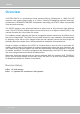
VIVOTEK Overview VIVOTEK IP8372 is a professional bullet camera offering 5-Megapixel or 1080p Full HD resolution with superb image quality up to 30 fps. Featuring 5-Megapixel resolution and highperformance H.264/MPEG-4/MJPEG compression technology, the IP8372 offers extra-smooth video and wide coverage. The IP8372 employs many advanced features to allow users to fully utilize the high definition video.
VIVOTEK Read Before Use The use of surveillance devices may be prohibited by law in your country. The Network Camera is not only a high-performance web-ready camera but can also be part of a flexible surveillance system. It is the user’s responsibility to ensure that the operation of such devices is legal before installing this unit for its intended use. It is important to first verify that all contents received are complete according to the Package Contents listed below.
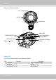
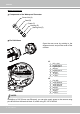
VIVOTEK Physical Description Lens IR LED Light Sensor Status LED Auto Focus Button Reset Button SD/SDHC/SDXC Card Slot NTSC-PAL switch NTSC General I/O Terminal Block PAL Status LED The LED indicates the status of the Network Camera. Item 1 2 3 LED status Steady Red Red LED off Blink Red every 0.15 sec. Blink Red every 0.15 sec.
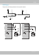
VIVOTEK DI/DO Diagram Please refer to the following illustration for the connection method. 12V +12V PIN 1 Power+12V PIN 3 or 5 Digital input PIN 2 Digital output PIN 4 or 6 Ground Gnd Camera Power BJT transistor 4 Gnd VDC 1 Camera Power Input 5 or 6 Switch Output 2 +30 VDC Max.
VIVOTEK Hardware Reset Reset Button The reset button is used to reset the system or restore the factory default settings. Sometimes resetting the system can return the camera to normal operation. If the system problems remain after reset, restore the factory settings and install again. Reset: Press and release the recessed reset button. Wait for the Network Camera to reboot. Restore: Press and hold the recessed reset button until the status LED rapidly blinks.
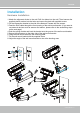
VIVOTEK Installation Hardware Installation 1. Attach the alignment sticker to the wall. Drill four holes into the wall. Then hammer the supplied plastic anchors into the holes and secure the plate with supplied screws. 2. Fix the intersection bracket to the side of the Network Camera with two screws. 3. Feed the RJ45 cable through the front opening of the wall mount bracket. (If you want to use external devices such as sensors and alarms, please refer to the assembling steps on the next page.) 4.
VIVOTEK Waterproof Connector Components of the Waterproof Connector Screw Nut (A) Seal (B) Seals (C) Housing (D) Sealing Nut (E) Pin Definitions Open the rear cover by rotating to the alignment mark, and pull the cover off the canister. Fix n Alig J3 8 J6 1 8 1 J3 1 1 2 3 4 5 6 7 8 DO+ (12V) Digital Output Digital Input 1 Ground Digital Input 2 Ground TV Out + TV Out - J6 1 2 3 4 5 6 7 8 Ext.
VIVOTEK Assembling Steps 1. Disassemble the components of the waterproof connector into part (A) ~ (E) as shown above. 2. Open the rear cover of the Network Camera. 3. Remove the rubber stopper from the bottom of the Network Camera and secure the screw nut (A) tightly. 4. If you need extra power for external devices, please feed the power cable through the wall mount bracket and the waterproof connector (E --> D --> B --> A) as the illustration shown below. Then connect the power cord to the socket.
VIVOTEK Cabling Assembly: RJ45 Cable Connector Components of the Waterproof Connector Sealing Nut (A) RJ45 Cable Dimension (unit: mm) Seal (B) Screw Nut (C) Housing (D) Gasket (E) Assembling Steps 1 Prepare an Ethernet cable and strip part of the sheath. 2 Insert the housing into the screw nut. (C) 3 (D) Insert the seal into the housing. (B) Recommended cable gauge: 24AWG (0.51 mm) 4 Insert the stripped Ethernet cable through the sealing nut and the housing.
VIVOTEK Network Deployment Setting up the Network Camera over the Internet This section explains how to configure the Network Camera to an Internet connection. 1. If you have external devices such as sensors and alarms, connect them to the general I/O terminal block. 2. Connect the camera to a switch via Ethernet cable. 3. Connect either the DC 12V or AC 24V power wires from the Network Camera to a power outlet.
VIVOTEK Internet connection via a router Before setting up the Network Camera over the Internet, make sure you have a router and follow the steps below. 1. Connect your Network Camera behind a router, the Internet environment is illustrated below. Regarding how to obtain your IP address, please refer to Software Installation on page 16 for details. WAN (Wide Area Network ) Internet Router IP address : from ISP POWER COLLISION 1 2 3 4 5 IP address : 192.168.0.3 Subnet mask : 255.255.255.
VIVOTEK Set up the Network Camera through Power over Ethernet (PoE) When using a PoE-enabled switch The Network Camera is PoE-compliant, allowing transmission of power and data via a single Ethernet cable. Follow the below illustration to connect the Network Camera to a PoE-enabled switch via Ethernet cable.
VIVOTEK Software Installation Installation Wizard 2 (IW2), free-bundled software included on the product CD, helps you set up your Network Camera on the LAN. IW2 1. Install IW2 under the Software Utility directory from the software CD. Double click the IW2 shortcut on your desktop to launch the program. Installation Wizard 2 2. The program will conduct an analysis of your network environment. After your network environment is analyzed, please click Next to continue the program. 3.
VIVOTEK Ready to Use 1. Access the Network Camera on the LAN. 2. Retrieve live video through a web browser or the included ST-7501 recording software.
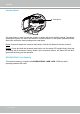
VIVOTEK NOTE: If you want to use the supplied sun shield for outdoor environments, please follow the steps below to install: 1. Tighten the supplied two hex couplers. 2. Attach the supplied sun shield to the Network Camera and slide it to the desired position. 3. Fix the sun shield with the supplied two screws. 2 1 3 Accessories VIVOTEK also provides other accessories for versatile applications as the following illustrations. Please visit VIVOTEK's official website for more purchase information.
VIVOTEK Accessing the Network Camera This chapter explains how to access the Network Camera through web browsers, RTSP players, 3GPP-compatible mobile devices, and VIVOTEK recording software. Using Web Browsers Use Installation Wizard 2 (IW2) to access to the Network Cameras on the LAN. If your network environment is not a LAN, follow these steps to access the Netwotk Camera: 1. Launch your web browser (e.g., Microsoft® Internet Explorer or Mozilla Firefox). 2.
VIVOTEK it is highly recommended to set a password for the Network Camera. For more information about how to enable password protection, please refer to Security on page 79. ► If you see a dialog box indicating that your security settings prohibit running ActiveX ® Controls, please enable the ActiveX ® Controls for your browser. 1. Choose Tools > Internet Options > Security > Custom Level. 2. Look for Download signed ActiveX ® controls; select Enable or Prompt. Click OK. 3.
VIVOTEK Using RTSP Players To view the MPEG-4 streaming media using RTSP players, you can use one of the following players that support RTSP streaming. Quick Time Player VLC media player VLC media player 1. Launch the RTSP player. mpegable Player 2. Choose File > Open URL. A URL dialog box will pop up. 3.
VIVOTEK Using 3GPP-compatible Mobile Devices To view the streaming media through 3GPP-compatible mobile devices, make sure the Network Camera can be accessed over the Internet. For more information on how to set up the Network Camera over the Internet, please refer to Setup the Network Camera over the Internet on page 13. To utilize this feature, please check the following settings on your Network Camera: 1.
VIVOTEK Using VIVOTEK Recording Software The product software CD also contains recording software, allowing simultaneous monitoring and video recording for multiple Network Cameras. Please install the recording software; then launch the program to add the Network Camera to the Channel list. For detailed information about how to use the recording software, please refer to the user’s manual of the software or download it from http://www.vivotek.com.
VIVOTEK Main Page This chapter explains the layout of the main page. It is composed of the following sections: VIVOTEK INC. Logo, Host Name, Camera Control Area, Configuration Area, Menu, and Live Video Window. VIVOTEK INC. Logo Resize Buttons Host Name Configuration Area Camera Control Area Hide Button Live View Window VIVOTEK INC. Logo Click this logo to visit the VIVOTEK website. Host Name The host name can be customized to fit your needs. For more information, please refer to System on page 35.
VIVOTEK Auto Focus There are two options for you to fine-tune the camera focus. Auto Focus Button Press the button, and the camera firmware will automatically perform an auto-sensing process on its vari-focal lens to look for the best focus. The process takes about a minute to complete. This function applies when you see the image is out of focus when the surrounding lighting condition is changed drastically for some reasons. You can press the button for longer than 1 second to perform a full-range scan.
VIVOTEK Configuration Area Client Settings: Click this button to access the client setting page. For more information, please refer to Client Settings on page 29. Configuration: Click this button to access the configuration page of the Network Camera. It is suggested that a password be applied to the Network Camera so that only the administrator can configure the Network Camera. For more information, please refer to Configuration on page 34.
VIVOTEK Video and Audio Control Buttons: Depending on the Network Camera model and Network Camera configuration, some buttons may not be available. Snapshot: Click this button to capture and save still images. The captured images will be displayed in a pop-up window. Right-click the image and choose Save Picture As to save it in JPEG (*.jpg) or BMP (*.bmp) format. Digital Zoom: Click and uncheck “Disable digital zoom” to enable the zoom operation.
VIVOTEK ■ The following window is displayed when the video mode is set to MJPEG: Video Title Title and Time Video (HTTP-V) 2011/02/25 17:08:56 Time Video 17:08:56 2011/06/25 Video Control Buttons Video Title: The video title can be configured. For more information, please refer to Media > Image on page 79. Time: Display the current time. For more information, please refer to Media > Image on page 79. Title and Time: Video title and time can be stamped on the streaming video.
VIVOTEK Client Settings This chapter explains how to select the stream transmission mode and saving options on the local computer. When completed with the settings on this page, click Save on the page bottom to enable the settings. H.264 / MPEG-4 Media Options H.264/MPEG-4 Media Options Select to stream video or audio data or both. This is enabled only when the video mode is set to H.264 or MPEG-4. H.264 / MPEG-4 Protocol Options H.
VIVOTEK MP4 Saving Options Users can record live video as they are watching it by clicking page. Here, you can specify the storage destination and file name. Start MP4 Recording on the main Folder: Specify a storage destination for the recorded video files. File name prefix: Enter the text that will be appended to the front of the video file name. Add date and time suffix to the file name: Select this option to append the date and time to the end of the file name.
VIVOTEK Joystick Settings Enable Joystick Connect to the USB plug of the joystick to a USB port on your management computer. Once a USB joystick is connected, the related joystick configuration will be available on the Client settings window. The joystick should work properly without installing any other driver or software. Then you can begin to configure the joystick settings of connected devices. Please follow the instructions below to enable joystick settings. 1. Click on the Configure buttons button.
VIVOTEK Buttons Configuration In the Joystick Settings window, you can use the combinations of pull-down menus, Actions and Button number, to assign joystick buttons with different functions. The number of buttons may differ from the joystick you attached. Please follow the steps below to configure your joystick buttons: 1. Select the number of the button you want to configure from its pull-down list. For example: Assign Preset 1 (move to preset 1 position) to Button 1. 2.
VIVOTEK NOTE: • • If you want to assign Preset actions to your joystick, the PTZ preset locations should be configured in advance. If your joystick is not working properly, it may need to be calibrated. Click the Calibrate button to open the Game Controllers window located in Microsoft Windows control panel and follow the instructions for trouble shooting. • The joystick will appear in the Game Controllers list in the Windows Control panel.
VIVOTEK Configuration Click Configuration on the main page to enter the camera setting pages. Note that only Administrators can access the configuration page. VIVOTEK offers an easy-to-use user interface that helps you set up your network camera with minimal effort. To simplify the setting procedure, two types of user interfaces are available: Advanced Mode for professional users and Basic Mode for entry-level users.
VIVOTEK Advanced Mode Navigation Area Configuration List Click to switch to Basic Mode Firmware Version Each function on the configuration list will be explained in the following sections. Those functions that are displayed only in Advanced Mode are tagged with Advanced Mode . If you want to set up advanced functions, please click [Advanced Mode] on the bottom of the configuration list to quickly switch over.
VIVOTEK System time Keep current date and time: Select this option to preserve the current date and time of the Network Camera. The Network Camera’s internal real-time clock maintains the date and time even when the power of the system is turned off. Synchronize with computer time: Select this option to synchronize the date and time of the Network Camera with the local computer. The read-only date and time of the PC is displayed as updated. Manual: The administrator can enter the date and time manually.
VIVOTEK System > Homepage layout Advanced Mode This section explains how to set up your own customized homepage layout. General settings This column shows the settings of your hompage layout. You can manually select the background and font colors in Theme Options (the second tab on this page). The settings will be displayed automatically in this Preview field.
VIVOTEK Theme Options Here you can change the color of your homepage layout. There are three types of preset patterns for you to choose from. The new layout will simultaneously appear in the Preview filed. Click Save to enable the settings.
VIVOTEK ■ Follow the steps below to set up the customized homepage: 1. Click Custom on the left column. 2. Click the field where you want to change the color on the right column. Color Selector Custom Pattern 3. The palette window will prompt as follows. 2 3 1 4 4. Drag the slider bar and click on the left square to select a desired color. 5. The selected color will be displayed in the corresponding fields and in the Preview column. 6. Click Save to enable the settings.
VIVOTEK System > Logs Advanced Mode This section explains how to configure the Network Camera to send the system log to a remote server as backup. Log server settings Follow the steps below to set up the remote log: 1. Select Enable remote log. 2. In the IP address text box, enter the IP address of the remote server. 2. In the port text box, enter the port number of the remote server. 3. When completed, click Save to enable the setting.
VIVOTEK Access log Access log displays the access time and IP address of all viewers (including operators and administrators) in a chronological order. The access log is stored in the Network Camera’s buffer area and will be overwritten when reaching a certain limit. System > Parameters Advanced Mode The View Parameters page lists the entire system’s parameters. If you need technical assistance, please provide the information listed on this page.
VIVOTEK System > Maintenance This chapter explains how to restore the Network Camera to factory default, upgrade firmware version, etc. General settings > Upgrade firmware This feature allows you to upgrade the firmware of your Network Camera. It takes a few minutes to complete the process. Note: Do not power off the Network Camera during the upgrade! Follow the steps below to upgrade the firmware: 1. Download the latest firmware file from the VIVOTEK website. The file is in .pkg file format. 2.
VIVOTEK General settings > Restore This feature allows you to restore the Network Camera to factory default settings. Network: Select this option to retain the Network Type settings (please refer to Network Type on page 61). Daylight Saving Time: Select this option to retain the Daylight Saving Time settings (please refer to Import/Export files below on this page). Custom Language: Select this option to retain the Custom Language settings.
VIVOTEK 3. Open the file with Microsoft® Notepad and locate your time zone; set the start and end time of DST. When completed, save the file. In the example below, DST begins each year at 2:00 a.m. on the second Sunday in March and ends at 2:00 a.m. on the first Sunday in November. Update daylight saving time rules: Click Browse… and specify the XML file to update. If the incorrect date and time are assigned, you will see the following warning message when uploading the file to the Network Camera.
VIVOTEK The following message is displayed when attempting to upload an incorrect file format. Export language file: Click to export language strings. VIVOTEK provides nine languages: English, Deutsch, Español, Français, Italiano, 日本語, Português, 簡体中文, and 繁體中文. Update custom language file: Click Browse… and specify your own custom language file to upload. Export configuration file: Click to export all parameters for the device and user-defined scripts.
VIVOTEK Media > Image Advanced Mode This section explains how to configure the image settings of the Network Camera. It is composed of the following four columns: General settings, Picture settings, Exposure, and Privacy mask. General settings Show timestamp and video title in video and snapshots: Enter a name that will be displayed on the title bar of the live video as the picture shown below.
VIVOTEK Day/Night Settings Switch to B/W in night mode Select this to enable the Network Camera to automatically switch to B/W during night mode. Turn on external IR illuminator in night mode Select this to turn on an external IR illuminator (connected via Digital Output lines) when the camera detects low light condition and enters the night mode.
VIVOTEK Image settings On this page, you can tune the White balance, Image adjustment and WDR enhanced . Sensor Setting 1: For normal situations Sensor Setting 2: For special situations White balance: Adjust the value for the best color temperature. ■ Auto: Firmware will automatically adjust the color temperature in the current lighting condition in response to different light sources. You may follow the steps below to adjust the white balance to the best color temperature. 1.
VIVOTEK higher luminance for detailed expression for both dark and lighted areas of an image. ■ Enable low light compensation: Select this option in low light mode, and the values of sharpness and brightness will change automatically. This function also benefits from an automated noise reduction feature. WDR enchanced: This function allows users to identify more details of objects in the high contrast environment especially for details in the shaded area.
VIVOTEK Measurement Window: This function allows user to set measurement window(s) for low light compesation. ■ Full view: Calculate the full range of view and offer appropriate light compesation. ■ Custom: This option allows you to manually add customized windows as inclusive or exclusive regions. A total of 10 windows can be set. The inclusive window refers to “weighted window“; the exclusive window refers to “ignored window“. It adopts the weighted averages method to calculate the value.
VIVOTEK Auto: If you set Exposure mode as Auto, the Exposure time and Gain control will not be configurable since the sensor library will automatically adjust the value according to the ambient light. Then you can configure iris mode as “indoor” or “outdoor” to reach the best image quality. ■ Iris mode: Select Indoor or Outdoor iris mode to adapt to the installation. The preset iris aperture setting will apply. You can click Restore to recall the original settings without incorporating the changes.
VIVOTEK Focus Focus, also known as Remote Focus, is applicable to Network Cameras that are equipped with stepping motor lens. The automated focus adjustment function eliminates the needs to physically adjust camera focus. In an outdoor deployment consisting of a large number of cameras, the auto focus function can be very helpful when these cameras become out of focus after days or weeks of operation. And that can easily result from the effects of natural forces, e.g.
VIVOTEK Privacy mask Advanced Mode Click Privacy Mask to open the settings page. On this page, you can block out sensitive zones to address privacy concerns. 2010/12/09 17:08:56 2010/12/09 17:08:56 ■ To set the privacy mask windows, follow the steps below: 1. Click New to add a new window. 2. You can use the mouse cursor to size and drag-drop the window, which is recommended to be at least twice the size of the object (height and width) you want to cover. 3.
VIVOTEK Media > Video Advanced Mode FOV (Field of View) Select a resolution from the list. The default is 5 Megapixels, and if bandwidth or frame rate per second is of the concern you can select a lower resolution. The configurable options are: 5MP (4:3) at 10fps, 3MP (4:3) 20fps, 2MP (4:3) 30fps, 1080P (16:9) 30fps, and 720P (16:9) at 60fps. Cropping Setting: When you select a resolution other than the default maximum 5MP, a Cropping Setting window will prompt.
VIVOTEK Stream settings Advanced Mode This Network Camera supports multiple streams with frame sizes ranging from 176 x 144 to 2560 x 1920. The definition of multiple streams: ■ Stream 1: Users can define the "Region of Interest" (viewing region) and the "Output Frame size" (size of the live view window). ■ Stream 2: Users can define the "Region of Interest" (viewing region) and the "Output Frame size" (size of the live view window).
VIVOTEK NOTE: ► All the items in the “Region of Interest” should not be larger than the “Output Frame Size“ (current maximum resolution).
VIVOTEK Click the stream setting to display the detailed information. The maximum frame size will follow your settings in the above Viewing Window sections. This Network Camera offers real-time H.264, MPEG-4 and MJEPG compression standards (Triple Codec) for real-time viewing. If H.264 / MPEG-4 mode is selected, the video is streamed via RTSP protocol.
VIVOTEK The frame rate will decrease if you select a higher resolution. ■ Intra frame period Determine how often to plant an I frame. The shorter the duration, the more likely you will get better video quality, but at the cost of higher network bandwidth consumption. Select the intra frame period from the following durations: 1/4 second, 1/2 second, 1 second, 2 seconds, 3 seconds, and 4 seconds.
VIVOTEK ■ Frame size You can set up different video resolution for different viewing devices. For example, set a smaller frame size and lower bit rate for remote viewing on mobile phones and a larger video size and a higher bit rate for live viewing on web browsers. Note that a larger frame size takes up more bandwidth. ■ Maximum frame rate This limits the maximum refresh frame rate per second. Set the frame rate higher for smoother video quality.
VIVOTEK Media > Audio Audio Settings Mute: Select this option to disable audio transmission from the Network Camera to all clients. Note that if muted, no audio data will be transmitted even if audio transmission is enabled on the Client Settings page. In that case, the following message is displayed: External microphone input: Select the gain of the external audio input according to ambient conditions. Adjust the gain from +21 db (most sensitive) or -33 db (least sensitive).
VIVOTEK Network > General settings This section explains how to configure a wired network connection for the Network Camera. Network Type LAN Select this option when the Network Camera is deployed on a local area network (LAN) and is intended to be accessed by local computers. The default setting for the Network Type is LAN. Rememer to click Save when you complete the Network setting.
VIVOTEK Primary DNS: The primary domain name server that translates hostnames into IP addresses. Secondary DNS: Secondary domain name server that backups the Primary DNS. Primary WINS server: The primary WINS server that maintains the database of computer names and IP addresses. Secondary WINS server: The secondary WINS server that maintains the database of computer names and IP addresses.
VIVOTEK NOTENOTE: ► If the default ports are already used by other devices connected to the same router, the Network Camera will select other ports for the Network Camera. ► If UPnP TM is not supported by your router, you will see the following message: Error: Router does not support UPnP port forwarding. ► Steps to enable the UPnP TM user interface on your computer: Note that you must log on to the computer as a system administrator to install the UPnP TM components. 1.
VIVOTEK 4. In the Networking Services dialog box, select Universal Plug and Play and click OK. 5. Click Next in the following window. 6. Click Finish. UPnP TM is enabled. ► How does UPnP TM work? UPnP TM networking technology provides automatic IP configuration and dynamic discovery of devices added to a network. Services and capabilities offered by networked devices, such as printing and file sharing, are available among each other without the need for cumbersome network configuration.
VIVOTEK Enable IPv6 Select this option and click Save to enable IPv6 settings. Please note that this only works if your network environment and hardware equipment support IPv6. The browser should be Microsoft® Internet Explorer 6.5, Mozilla Firefox 3.0 or above. When IPv6 is enabled, by default, the network camera will listen to router advertisements and be assigned with a link-local IPv6 address accordingly. IPv6 Information: Click this button to obtain the IPv6 information as shown below.
VIVOTEK Please follow the steps below to link to an IPv6 address: 1. Open your web browser. 2. Enter the link-global or link-local IPv6 address in the address bar of your web browser. 3. The format should be: http://[2001:0c08:2500:0002:0202:d1ff:fe04:65f4]/ IPv6 address 4. Press Enter on the keyboard or click Refresh button to refresh the webpage.
VIVOTEK Port HTTPS port: By default, the HTTPS port is set to 443. It can also be assigned to another port number between 1025 and 65535. Two way audio port: By default, the two way audio port is set to 5060. Also, it can also be assigned to another port number between 1025 and 65535. The Network Camera supports two way audio communication so that operators can transmit and receive audio simultaneously.
VIVOTEK Audio is being transmitted to the Network Camera 2012/08/09 17:08:56 Mute Talk Button Mic Volume Click to enable audio transmission to the Network Camera; click to turn off the audio. To stop talking, click again. microphone; click to adjust the volume of FTP port: The FTP server allows the user to save recorded video clips. You can utilize VIVOTEK's Installation Wizard 2 to upgrade the firmware via FTP server. By default, the FTP port is set to 21.
VIVOTEK Network > Streaming protocols Advanced Mode HTTP streaming To utilize HTTP authentication, make sure that your have set a password for the Network Camera first; please refer to Security > User account on page 79 for details. Authentication: Depending on your network security requirements, the Network Camera provides two types of security settings for an HTTP transaction: basic and digest.
VIVOTEK URL command -- http://:/ For example, when the Access name for stream 2 is set to video2.mjpg: 1. Launch Mozilla Firefox or Netscape. 2. Type the above URL command in the address bar. Press Enter. 3. The JPEG images will be displayed in your web browser. http://192.168.5.151/video2.
VIVOTEK Authentication: Depending on your network security requirements, the Network Camera provides three types of security settings for streaming via RTSP protocol: disable, basic, and digest. If basic authentication is selected, the password is sent in plain text format, but there can be potential risks of it being intercepted. If digest authentication is selected, user credentials are encrypted using MD5 algorithm, thus providing better protection against unauthorized access.
VIVOTEK Multicast settings for stream 1 ~ 3: Click the items to display the detailed configuration information. Select the Always multicast option to enable multicast for stream 1 ~ 3. Unicast video transmission delivers a stream through point-to-point transmission; multicast, on the other hand, sends a stream to the multicast group address and allows multiple clients to acquire the stream at the same time by requesting a copy from the multicast group address.
VIVOTEK Network > DDNS This section explains how to configure the dynamic domain name service for the Network Camera. DDNS is a service that allows your Network Camera, especially when assigned with a dynamic IP address, to have a fixed host and domain name. Express link Express Link is a free service provided by VIVOTEK server, which allows users to register a domain name for a network device. One URL can only be mapped to one MAC address.
VIVOTEK Manual setup DDNS: Dynamic domain name service Enable DDNS: Select this option to enable the DDNS setting. Provider: Select a DDNS provider from the provider drop-down list. VIVOTEK offers Safe100.net, a free dynamic domain name service, to VIVOTEK customers. It is recommended that you register Safe100.net to access VIVOTEK’s Network Cameras from the Internet. Additionally, we offer other DDNS providers, such as Dyndns.org(Dynamic), Dyndns. org(Custom), TZO.com, DHS.
VIVOTEK [Register] Successfully Your account information has been mailed to registered e-mail address 4. Select Enable DDNS and click Save to enable the setting. ■ CustomSafe100 VIVOTEK offers documents to establish a CustomSafe100 DDNS server for distributors and system integrators. You can use CustomSafe100 to register a dynamic domain name if your distributor or system integrators offer such services. 1. In the DDNS column, select CustomSafe100 from the drop-down list. 2.
VIVOTEK Network > QoS (Quality of Service) Advanced Mode Quality of Service refers to a resource reservation control mechanism, which guarantees a certain quality to different services on the network. Quality of service guarantees are important if the network capacity is insufficient, especially for real-time streaming multimedia applications. Quality can be defined as, for instance, a maintained level of bit rate, low latency, no packet dropping, etc.
VIVOTEK QoS/DSCP (the DiffServ model) DSCP-ECN defines QoS at Layer 3 (Network Layer). The Differentiated Services (DiffServ) model is based on packet marking and router queuing disciplines. The marking is done by adding a field to the IP header, called the DSCP (Differentiated Services Codepoint). This is a 6-bit field that provides 64 different class IDs. It gives an indication of how a given packet is to be forwarded, known as the Per Hop Behavior (PHB).
VIVOTEK Network > SNMP (Simple Network Management Protocol) Advanced Mode This section explains how to use the SNMP on the network camera. The Simple Network Management Protocol is an application layer protocol that facilitates the exchange of management information between network devices. It helps network administrators to remotely manage network devices and find, solve network problems with ease. ■ The SNMP consists of the following three key components: 1.
VIVOTEK Security > User Account This section explains how to enable password protection and create multiple accounts. Root Password The administrator account name is “root”, which is permanent and can not be deleted. If you want to add more accounts in the Manage User column, please apply the password for the “root” account first. 1. Type the password identically in both text boxes, then click Save to enable password protection. 2.
VIVOTEK Security > HTTPS (Hypertext Transfer Protocol over SSL) Advanced Mode This section explains how to enable authentication and encrypted communication over SSL (Secure Socket Layer). It helps protect streaming data transmission over the Internet on higher security level. Create and Install Certificate Method Before using HTTPS for communication with the Network Camera, a Certificate must be created first. There are three ways to create and install a certificate: Create self-signed certificate 1.
VIVOTEK 5. Click Save to preserve your configuration, and your current session with the camera will change to the encrypted connection. 6. If your web session does not automatically change to an encrypted HTTPS session, click Home to return to the main page. Change the URL address from “http://” to “https://“ in the address bar and press Enter on your keyboard. Some Security Alert dialogs will pop up. Click OK or Yes to enable HTTPS. https:// https://192.168.5.151/index.
VIVOTEK Create certificate request and install 1. Select the option from the Method pull-down menu. 2. Click Create certificate to proceed. 3. The following information will show up in a pop-up window after clicking Create. Then click Save to generate the certificate request. 4. The Certificate request window will prompt. If you see the following Information bar, click OK and click on the Information bar at the top of the page to allow pop-ups.
VIVOTEK 5. Look for a trusted certificate authority, such as Symantec’s VeriSign Authentication Services, that issues digital certificates. Sign in and purchase the SSL certification service. Copy the certificate request from your request prompt and paste it in the CA’s signing request window. Proceed with the rest of the process as CA’s instructions on their webpage. 6. Once completed, your SSL certificate should be delivered to you via an email or other means.
VIVOTEK 7. Open a new edit, paste the certificate contents, and press ENTER at the end of the contents to add an empty line. 8. Convert file format from DOS to UNIX. Open File menu > Conversions > DOS to Unix.
VIVOTEK 9. Save the edit using the “.crt” extension, using a file name like “CAcert.crt.” 10. Return to the original firmware session, use the Browse button to locate the crt certificate file, and click Upload to enable the certification.
VIVOTEK 11. When the certifice file is successfully loaded, its status will be stated as Active. Note that a certificate must have been created and installed before you can click on the “Save" button for the configuration to take effect. 12.To begin an encrypted HTTPS session, click Home to return to the main page. Change the URL address from “http://” to “https://“ in the address bar and press Enter on your keyboard. Some Security Alert dialogs will pop up. Click OK or Yes to enable HTTPS.
VIVOTEK Security > Access List Advanced Mode This section explains how to control access permission by verifying the client PC’s IP address. General Settings Maximum number of concurrent streaming connection(s) limited to: Simultaneous live viewing for 1~10 clients (including stream 1 and stream 2). The default value is 10. If you modify the value and click Save, all current connections will be disconnected and automatically attempt to re-link (IE Explore or Quick Time Player).
VIVOTEK ■ Refresh: Click this button to refresh all current connections. ■ Add to deny list: You can select entries from the Connection Status list and add them to the Deny List to deny access. Please note that those checked connections will only be disconnected temporarily and will automatically try to re-link again (IE Explorer or Quick Time Player). If you want to enable the denied list, please check Enable access list filtering and click Save in the first column.
VIVOTEK There are three types of rules: Single: This rule allows the user to add an IP address to the Allowed/Denied list. For example: 192.168.2.1 Network: This rule allows the user to assign a network address and corresponding subnet mask to the Allow/Deny List. The address and network mask are written in CIDR format. For example: IP address 192.168.2.x will be bolcked. If IPv6 filter is preferred, you will be prompted by the following window.
VIVOTEK Security > IEEE 802.1X Advanced Mode Enable this function if your network environment uses IEEE 802.1x, which is a port-based network access control. The network devices, intermediary switch/access point/hub, and RADIUS server must support and enable 802.1x settings. The 802.1x standard is designed to enhance the security of local area networks, which provides authentication to network devices (clients) attached to a network port (wired or wireless).
VIVOTEK 3. When all settings are complete, move the Network Camera to the protected LAN by connecting it to an 802.1x enabled switch. The devices will then start the authentication automatically. NOTE: NOTE ► The authentication process for 802.1x: 1. The Certificate Authority (CA) provides the required signed certificates to the Network Camera (the supplicant) and the RADIUS Server (the authentication server). 2. A Network Camera requests access to the protected LAN using 802.
VIVOTEK PTZ > PTZ settings Advanced Mode This section explains how to control the Network Camera’s Pan/Tilt/Zoom operation. There are two ways to enable the function: Digital: Control the e-PTZ operation. It allows users to quickly move the focus to a target area for close-up viewing without physically moving the camera.
VIVOTEK Auto pan/patrol speed: Select the speed from 1~5 (slow/fast) to set up the Auto pan/patrol speed control. Zoom factor display If you check this item, the zoom indicator will be displayed on the home page when you zoom in or zoom out the live viewing window as the picture shown on the next page. When completed with the settings of e-PTZ, click Save to enable the settings on this page. Home page in E-PTZ Mode 2012/08/10 17:08:56 x1.
VIVOTEK Patrol settings You can select some preset positions for the Network Camera to patrol. Please follow the steps below to set up a patrol schedule: 1. Select the preset locations on the list, and click . 2. The selected preset locations will be displayed on the Patrol locations list. 3. Set the Dwelling time for the preset location during auto patrol. 4. If you want to delete a preset location from the Patrol locations list, select it and click Remove. 5.
VIVOTEK Event > Event settings Advanced Mode This section explains how to configure the Network Camera to responds to particular situations (event). A typical application is that when a motion is detected, the Network Camera sends buffered images to an FTP server or e-mail address as notifications. Click on Help, there is an illustration shown in the pop-up window explains that an event can be triggered by many sources, such as motion detection or external digital input devices.
VIVOTEK ■ Event name: Enter a name for the event setting. ■ Enable this event: Select this option to enable the event setting. ■ Priority: Select the relative importance of this event (High, Normal, or Low). Events with a higher priority setting will be executed first. seconds: Enter the duration in seconds to pause ■ Detect next motion detection or digital input after motion detection after a motion is detected. This can prevent event triggers to be too frequently delivered. 1.
VIVOTEK ■ Camera tampering detection This option allows the Network Camera to trigger when the camera detects that is is being tampered with. To enable this function, you need to enable the Tampering Detection function first. Please refer to page 111 for detailed information. ■ Manual Trigger This option allows user to enable event triggers manually by clicking the on/off button on the homepage. Please configure 1 ~ 3 events before using this function. 3.
VIVOTEK Add server To set an event with recorded video or snapshots, it is necessary to configure the server and media settings so that the Network Camera will know what action to take (such as which server to send the media files to) when a trigger is activated. Click Add server to open the server setting window. You can specify where the notification messages are sent when a trigger is activated. A total of 5 server settings can be configured.
VIVOTEK To verify if the email settings are correctly configured, click Test. The result will be shown in a pop-up window. If successful, you will also receive an email indicating the result. Click Save server to enable the settings. To note that after you set up the first event server, a new item for event server will automatically show up on the Server list. If you wish to add other server options, click Add server.
VIVOTEK ■ Passive mode Most firewalls do not accept new connections initiated from external requests. If the FTP server supports passive mode, select this option to enable passive mode FTP and allow data transmission to pass through the firewall. To verify if the FTP settings are correctly configured, click Test. The result will be shown in a pop-up window as shown below. If successful, you will also receive a test.txt file on the FTP server. Click Save server to enable the settings.
VIVOTEK Network storage: Select to send the media files to a network storage location when a trigger is activated. Please refer to NAS server on page 115 for details. Click Save server to enable the settings. ■ SD Test: Click to test your SD card. The system will display a message indicating success or failure. If you want to use your SD card for local storage, please format it before use. Please refer to page 103 for detailed information. ■ View: Click this button to open a file list window.
VIVOTEK Click 20120820 to open the directory: The format is: HH (24r) Click to open the file list for that hour 2012/08/20 2012/08/20 Click to go back to the previous level of the directory Click to delete selected items Click to delete all recorded data 2012/08/20 2012/08/20 The format is: File name prefix + Minute (mm) You can set up the file name prefix on Add media page. Please refer to next page for detailed information.
VIVOTEK Add media Click Add media to open the media setting window. You can specify the type of media that will be sent when a trigger is activated. A total of 5 media settings can be configured. There are three choices of media types available: Snapshot, Video Clip, and System log. Select the item to display the detailed configuration options. You can configure either one or all of them. Media type - Snapshot Select to send snapshots when a trigger is activated.
VIVOTEK ■ Add date and time suffix to the file name Select this option to add a date/time suffix to the file name. For example: Snapshot_20101213_100341 File name prefix Date and time suffix The format is: YYYYMMDD_HHMMSS Click Save media to enable the settings. To note that after you set up the first media server, a new column for media server will automatically show up on the Media list. If you wish to add more other media options, click Add media.
VIVOTEK ■ Maximum file size Specify the maximum file size allowed. ■ File name prefix Enter the text that will be appended to the front of the file name. For example: Video_20120813_100341 File name prefix Date and time suffix The format is: YYYYMMDD_HHMMSS Click Save media to enable the settings. Media type - System log Select to send a system log when a trigger is activated. Click Save media to enable the settings, then click Close to exit the page.
VIVOTEK In the Event settings column, the Servers and Medias you configured will be listed; please make sure the Event -> Status is indicated as ON, in order to enable the event triggering action. When completed, click Save event to enable the settings and click Close to exit Event Settings page. The new Event / Server settings / Media will appear in the event drop-down list on the Event setting page.
VIVOTEK Customized Script This function allows you to upload a sample script (.xml file) to the webpage, which will save your time on configuring the settings. Please note that there is a limited number of customized scripts you can upload; if the current amount of customized scripts has reached the limit, an alert message will pop up. If you need more information, please ask for VIVOTEK technical support.
VIVOTEK Applications > Motion detection This section explains how to configure the Network Camera to enable motion detection. A total of three motion detection windows can be configured. 2010/12/10 17:08:56 Motion Detection Setting 1: For normal situations hallway Follow the steps below to enable motion detection: Follow the steps below to enable motion detection: Motion Detection Setting 2: For special situations 1. Click New to add a new motion detection window. 2.
VIVOTEK A green bar indicates that even though motions have been detected, the event has not been triggered because the image variations still fall under the defined threshold. Percentage = 30% If you want to configure other motion detection settings for day/night/schedule mode, please click Profile to open the Motion Detection Profile Settings page as shown below. A total of three motion detection windows can be configured on this page as well.
VIVOTEK NOTE NOTE: ► How does motion detection work? A C B D There are two motion detection parameters: Sensitivity and Percentage. In the illustration above, frame A and frame B are two sequential images. Pixel differences between the two frames are detected and highlighted in gray (frame C) and will be compared with the sensitivity setting. Sensitivity is a value that expresses the sensitivity to moving objects.
VIVOTEK Applications > DI and DO Advanced Mode Connect DI or DO devices to the camera's terminal block, the camera will automatically detect the current connection state as pulled-high or pulled-low. You may then define the triggering condition. Digital input: Select High or Low as the state of the signal to define the "Normal status" for the digital input. Connect the digital input lines to the Network Camera, and the camera will report the current status.
VIVOTEK Recording > Recording settings Advanced Mode This section explains how to configure the recording settings for the Network Camera. Recording Settings Insert your SD card and click here to test NOTE NOTE: ► Please remember to format your SD card when using it for the first time. Please refer to page 117 for detailed information. Recording Settings Click Add to open the recording setting window.
VIVOTEK If you enable adaptive recording and enable time-shift cache stream on Camera A, only when an event is triggered on Camera A will the server record the full frame rate video stream; otherwise, it will only request the I frame data during normal monitoring, thus effectively save bandwidths and storage. NOTE NOTE: ► To enable adaptive recording, please make sure you’ve set up the trigger source such as Motion Detection, DI Device, or Manual Trigger.
VIVOTEK 2. Destination You can select the SD card or network storage (NAS) as the destination of the recording tasks. NAS server Click Add NAS server to open the server setting window and follow the steps below to set up: 1. Fill in the information for your server. For example: 3 Network storage path (\\server name or IP address\folder name) 1 2 4 User name and password for your server 2. Click Test to check the setting. The result will be shown in the pop-up window.
VIVOTEK If successful, you will receive a test.txt file on the network storage server. 3. Enter a server name. 4. Click Save to complete the settings and click Close to exit the page. ■ Capacity: You can choose either the entire free space available or limit the reserved space. The recording size limit must be larger than the reserved amount for cyclic recording. ■ Enable cyclic recording: If you check this item, when the maximum capacity is reached, the oldest file will be overwritten by the latest one.
VIVOTEK new recording name will appear in the drop-down list on the recording page as shown below. To remove a recording setting from the list, select a recording name from the drop-down list and click Delete. ■ Click Video (Name): Opens the Recording Settings page. ■ Click ON (Status): The Status will become OFF and stop recording. ■ Click NAS (Destination): Opens the file list of recordings as shown below. For more information about folder naming rules, please refer to page 101 for details.
VIVOTEK Local storage > SD card management Advanced Mode This section explains how to manage the local storage on the Network Camera. Here you can view SD card status, and implement SD card control. SD card staus This column shows the status and reserved space of your SD card. Please remember to format the SD card when using for the first time. no SD card SD card control ■ Enable cyclic storage: Check this item if you want to enable cyclic recording.
VIVOTEK Local storage > Content management Advanced Mode This section explains how to manage the content of recorded videos on the Network Camera. Here you can search and view the records and view the searched results. Searching and Viewing the Records This column allows the user to set up search criteria for recorded data. If you do not select any criteria and click Search button, all recorded data will be listed in the Search Results column.
VIVOTEK Search Results The following is an example of search results. There are four columns: Trigger time, Media type, Trigger type, and Locked. Click to sort the search results in either direction. Numbers of entries displayed on one page Enter a key word to filter the search results Highlight an item ■ View: Click on a search result which will highlight the selected item in purple as shown above. Click the View button and a media window will pop up to play back the selected file.
VIVOTEK ■ Lock/Unlock: Select the desired search results, then click this button. The selected items will become Locked, which will not be deleted during cyclic recording. You can click again to unlock the selections. For example: Click to switch pages ■ Remove: Select the desired search results, then click this button to delete the files.
VIVOTEK Appendix URL Commands for the Network Camera 1. Overview For some customers who already have their own web site or web control application, the Network Camera/Video Server can be easily integrated through URL syntax. This section specifies the external HTTP-based application programming interface. The HTTP-based camera interface provides the functionality to request a single image, control camera functions (PTZ, output relay etc.), and get and set internal parameter values.
VIVOTEK 3. General CGI URL Syntax and Parameters CGI parameters are written in lower-case and as one word without any underscores or other separators. When the CGI request includes internal camera parameters, these parameters must be written exactly as they are named in the camera or video server. The CGIs are organized in functionally-related directories under the cgi-bin directory. The file extension .cgi is required. Syntax: http:///cgi-bin/[/...]/.
VIVOTEK [&…] http:///cgi-bin/operator/getparam.cgi?[] [&…] http:///cgi-bin/admin/getparam.cgi?[] [&…] Where the should be [_] or [.]. If you do not specify any parameters, all the parameters on the server will be returned. If you specify only , the parameters of the related group will be returned. When querying parameter values, the current parameter values are returned.
VIVOTEK 6. Set Server Parameter Values Note: The access right depends on the URL directory. Method: GET/POST Syntax: http:///cgi-bin/anonymous/setparam.cgi? = [&=…][&update=][&return=] http:///cgi-bin/viewer/setparam.cgi? = [&=…][&update=] [&return=] http:///cgi-bin/operator/setparam.
VIVOTEK =\r\n [] Only the parameters that you set and are readable will be returned. Example: Set the IP address of server to 192.168.0.123: Request: http://myserver/cgi-bin/admin/setparam.cgi?network_ipaddress=192.168.0.123 Response: HTTP/1.0 200 OK\r\n Content-Type: text/html\r\n Context-Length: 33\r\n \r\n network.ipaddress=192.168.0.123\r\n 7.
VIVOTEK everything inside <> A description integer primary key SQLite data type. A 32-bit signed integer. The value is assigned a unique integer by the server. text SQLite data type. The value is a text string, stored using the database encoding (UTF-8, UTF-16BE or UTF-16-LE). coordinate x, y coordinate (eg. 0,0) window size window width and height (eg. 800x600) NOTE: The camera should not be restarted when parameters are changed.
VIVOTEK 7.1 system Group: system NAME VALUE DEFAULT SECURITY DESCRIPTION (get/set) hostname string[64] Mega-Pixel 1/6 Host name of server Network (Network Camera, Camera Wireless Network Camera, Video Server, Wireless Video Server). ledoff 0 6/6 Turn on (0) or turn off (1) all led indicators. lowlight 1 6/6 Turn on white light LED under all conditions. Only turn on white light LED in low light conditions.
VIVOTEK San_Francisco, Vancouver -280: GMT-07:00 Mountain Time, Denver -281: GMT-07:00 Arizona -240: GMT-06:00 Central America, Central Time, Mexico City, Saskatchewan -200: GMT-05:00 Eastern Time, New York, Toronto -201: GMT-05:00 Bogota, Lima, Quito, Indiana -180: GMT-04:30 Caracas -160: GMT-04:00 Atlantic Time, Canada, La Paz, Santiago -140: GMT-03:30 Newfoundland -120: GMT-03:00 Brasilia, Buenos Aires, Georgetown, Greenland -80: GMT-02:00 Mid-Atlantic -40: GMT-01:00 Azores, Cape_Verde_IS.
VIVOTEK 160: GMT 04:00 Abu Dhabi, Muscat, Baku, Tbilisi, Yerevan 180: GMT 04:30 Kabul 200: GMT 05:00 Ekaterinburg, Islamabad, Karachi, Tashkent 220: GMT 05:30 Calcutta, Chennai, Mumbai, New Delhi 230: GMT 05:45 Kathmandu 240: GMT 06:00 Almaty, Novosibirsk, Astana, Dhaka, Sri Jayawardenepura 260: GMT 06:30 Rangoon 280: GMT 07:00 Bangkok, Hanoi, Jakarta, Krasnoyarsk 320: GMT 08:00 Beijing, Chongging, Hong Kong, Kuala Lumpur, Singapore, Taipei 360: GMT 09:00 Osaka, Sapporo, Tokyo, Seoul, Yakutsk 380: GMT 09:30
VIVOTEK es -280,-240, daylight saving time. -241,-200, -201,-160, -140,-120, -80,-40,0, 40,41,80, 81,82,83, 120,140, 380,400,480 updateinterval 0, 0 6/6 0 to Disable automatic time 3600, adjustment, otherwise, it indicates 86400, the seconds between NTP automatic 604800, update intervals. 2592000 restore reset 0, N/A 7/6 Restore the system parameters to integer> seconds.
VIVOTEK default values except the custom language file the user has uploaded. This command can cooperate with other “restoreexceptXYZ” commands. When cooperating with others, the system parameters will be restored to the default value except for a union of the combined results.
VIVOTEK 7.1.1 system.info Subgroup of system: info (The fields in this group are unchangeable.) NAME VALUE DEFAULT SECURITY DESCRIPTION (get/set) modelname string[40] IP8372 0/7 Internal model name of the server (eg. IP7139) extendedmodelname string[40] IP8372 0/7 ODM specific model name of server (eg. DCS-5610). If it is not an ODM model, this field will be equal to “modelname” serialnumber mac 0/7 12 characters MAC address (without hyphens).
VIVOTEK 7.2 status Group: status NAME VALUE DEFAULT SECURITY DESCRIPTION (get/set) di_i<0~(ndi-1)> 0 1/7 0 => Inactive, normal 1 => Active, triggered (capability.ndi > 0) do_i<0~(ndo-1)> 0 1/7 0 => Inactive, normal 1 => Active, triggered (capability.ndo > 0) onlinenum_rtsp integer 0 6/7 Current number of RTSP connections. onlinenum_httppush integer 0 6/7 Current number of HTTP push server connections.
VIVOTEK 7.5 security Group: security NAME VALUE DEFAULT SECURITY DESCRIPTION (get/set) privilege_do view, operator, admin operator 1/6 Indicate which privileges and above can control digital output (capability.ndo > 0) privilege_camctrl view, operator, admin view 1/6 Indicate which privileges and above can control PTZ (capability.ptzenabled > 0 or capability.
VIVOTEK 7.6 network Group: network NAME VALUE DEFAULT SECURITY DESCRIPTION (get/set) preproces 6/6 An 32-bit integer, each bit can be set separately as follows: Bit 0 => HTTP service; Bit 1=> HTTPS service; Bit 2=> FTP service; Bit 3 => Two way audio and RTSP Streaming service; To stop service before changing its port settings. It’s recommended to set this parameter when change a service port to the port occupied by another service currently.
VIVOTEK router 6/6 Default gateway. 6/6 Primary DNS server. 6/6 Secondary DNS server. 6/6 Primary WINS server. 6/6 Secondary WINS server. address> dns1 dns2 wins1 wins2 7.6.1 802.1x Subgroup of network: ieee8021x (capability.protocol.ieee8021x > 0) NAME VALUE DEFAULT SECURITY DESCRIPTION (get/set) enable 0 6/6 Enable/disable IEEE 802.
VIVOTEK 7.6.2 QOS Subgroup of network: qos_cos (capability.protocol.qos.cos > 0) NAME VALUE DEFAULT SECURITY DESCRIPTION (get/set) enable 0 6/6 Enable/disable CoS (IEEE 802.1p) vlanid 1~4095 1 6/6 VLAN ID video 0~7 0 6/6 Video channel for CoS audio 0~7 0 6/6 Audio channel for CoS
VIVOTEK 7.6.3 IPV6 Subgroup of network: ipv6 (capability.protocol.ipv6 > 0) NAME VALUE DEFAULT SECURITY DESCRIPTION (get/set) enable 0 6/6 Enable IPv6. addonipaddress 6/6 IPv6 IP address. addonprefixlen 0~128 64 6/6 IPv6 prefix length. addonrouter 6/6 IPv6 router address. addondns 6/6 IPv6 DNS address. allowoptional 0 6/6 Allow manually setup of IP address setting. 7.6.
VIVOTEK =1 and capability.nmediastream > 1) s2_accessname string[32] video3.mjpg 1/6 Http server push access name for (capability.protocol.spush_mjpeg =1 and capability.nmediastream > 2) anonymousviewing 0 1/6 Enable anonymous streaming viewing. 7.6.6 HTTPS port Subgroup of network: https_port (capability.protocol.https > 0) NAME VALUE DEFAULT SECURITY DESCRIPTION (get/set) port 443, 1025 ~ 443 1/6 HTTPS port. 65535 7.6.
VIVOTEK s1_audiotrack -1 6/6 Enable audio for stream2. s2_audiotrack -1 6/6 Enable audio for stream3. 7.6.7.1 RTSP multicast Subgroup of network_rtsp_s<0~(n-1)>: multicast, n is stream count (capability.protocol.rtp.multicast > 0) NAME VALUE DEFAULT SECURITY DESCRIPTION (get/set) alwaysmulticast 0 4/4 Enable always multicast. ipaddress For n=0, 4/4 Multicast IP address. 239.128.1.99 For n=1, 239.128.1.100, and so on.
VIVOTEK 7.6.9 RTP port Subgroup of network: rtp NAME VALUE DEFAULT SECURITY DESCRIPTION (get/set) videoport 1025 ~ 65535 5556 6/6 Video channel port for RTP. (capability.protocol.rtp_unicast=1) audioport 1025 ~ 65535 5558 6/6 Audio channel port for RTP. (capability.protocol.rtp_unicast=1) 7.6.10 PPPoE Subgroup of network: pppoe (capability.protocol.pppoe > 0) NAME VALUE DEFAULT SECURITY DESCRIPTION (get/set) user string[128] 6/6 PPPoE account user name.
VIVOTEK address: ipv6list_i<0~9> String[44] 6/6 IPv6 address list. 7.8 Video input Group: videoin NAME VALUE DEFAULT SECURITY DESCRIPTION (get/set) cmosfreq 50, 60 60 4/4 CMOS frequency. (capability.videoin.type=2) whitebalance auto, manual, auto 4/4 “auto” indicates auto white rbgain “manual” indicates keep current value. “rbgain” indicates using rgain and gbain.
VIVOTEK function; 0(not support), 1(support) Bit 1 => Built-in or external camera; 0 (external), 1(built-in) Bit 2 => Support pan operation; 0(not support), 1(support) Bit 3 => Support tilt operation; 0(not support), 1(support) Bit 4 => Support zoom operation; 0(not support), 1(support) Bit 5 => Support focus operation; 0(not support), 1(support) text string[16] 4/4 Enclose caption. imprinttimestamp 0 4/4 Overlay time stamp on video.
VIVOTEK gbain. rgain 0~100 30 4/4 Manual set rgain value of gain control setting. bgain 0~100 30 4/4 Manual set bgain value of gain control setting. exposurelevel 0~12 6 4/4 Exposure level autoiris 0~1 0 4/4 set 1 to enable auto iris, set 0 to disable auto iris. irismode fixed, indoor, indoor 4/4 Video Iris for DC Iris. 0 4/4 Enable/disable wield dynamic outdoor enablewdr range.
VIVOTEK crop_preview < boolean > 0 1/4 Usage for UI of crop setting s<0~(m-1)>_codect mpeg4, mjpeg, H264 1/4 Video codec type. ype h264 2560x1920 1/4 Video resolution in pixels. 1000 4/4 Intra frame period in s<0~(m-1)>_resolu Reference tion capability_videoin _resolution s<0~(m-1)>_mpeg 250, 500, 1000, 4_intraperiod 2000, 3000, 4000 s<0~(m-1)>_mpeg cbr, vbr 4_ratecontrolmode milliseconds.
VIVOTEK s<0~(m-1)>_h264_ 250, 500, 1000, intraperiod 2000, 3000, 4000 s<0~(m-1)>_h264_ cbr, vbr ratecontrolmode 1000 4/4 milliseconds. s0~s1: cbr 4/4 s2: vbr s<0~(m-1)>_h264_ 1~5, quant 99, 100 Intra frame period in 3 cbr, constant bitrate vbr, fix quality 4/4 Quality of video when choosing vbr in “ratecontrolmode”. 99 is the customized manual input setting. 1 = worst quality, 5 = best quality. 100 is percentage mode.
VIVOTEK quality. 100 is percentage mode. s<0~(m-1)>_mjpeg 2~97 29 4/4 _qvalue Manual video quality level input. (s<0~(m-1)>_mjpeg_quant = 99) s<0~(m-1)>_mjpeg 1~100 49 4/4 _qpercent Manual video quality level input. (s<0~(m-1)>_mjpeg_quant = 100) s<0~(m-1)>_mjpeg 1000~20000000 16000000 4/4 _bitrate s<0~(m-1)>_mjpeg Set bit rate in bps when choosing cbr in “ratecontrolmode”. 1000~40000000 40000000 4/4 _maxvbrbitrate Set bit rate in bps when choosing vbr in “ratecontrolmode”.
VIVOTEK 7.8.1.1 Alternative video input profiles per channel In addition to the primary setting of video input, there can be alternative profile video input setting for each channel which might be for different scene of light (daytime or nighttime). Group: videoin_c0_profile_i<0~(m-1)> (capability.
VIVOTEK control setting. irismode fixed, indoor, indoor 4/4 Video Iris for DC Iris. 0 4/4 WDR enhanced. outdoor wdrc_mode 0~3 0: off 1: auto 2: always on 3: keep current value wdrc_strength 0~2 0 4/4 WDR enhanced. 0: low 1: medium 2: high 7.9 Video input preview The temporary settings for video preview Group: videoinpreview NAME VALUE DEFAULT SECURITY DESCRIPTION (get/set) exposuremode auto,fixed auto 4/4 Exposure Mode minexposure 1~32000 32000 4/4 Minimum exposure time.
VIVOTEK 1->4x, 2->8x agcmode auto,fixed auto 4/4 Set auto gain control mode. maxgain 0~100 100 4/4 Manual set maximum gain value. mingain 0~100 0 4/4 Manual set minimum gain value. autoiris 0 4/4 Enable auto Iris. 7.10 IR cut control Group: ircutcontrol (capability.
VIVOTEK 7.11 Image setting per channel Group: image_c<0~(n-1)> for n channel products NAME VALUE DEFAULT SECURITY DESCRIPTION (get/set) brightness -5~5 -5 4/4 Adjust brightness of image according to mode settings. saturation -5~5,100 0 4/4 Adjust saturation of image according to mode settings. 100 for saturation percentage mode.
VIVOTEK percentage when sharpness=100 profile_i0_gammacurve 0~100 0 4/4 Gamma curve profile_i0_lowlightmode 1 4/4 Enable/disable low light mode.
VIVOTEK 7.12 Image setting for preview Group: imagepreview_c<0~(n-1)> for n channel products NAME VALUE DEFAULT SECURITY DESCRIPTION (get/set) brightness -5~5 -5 4/4 Adjust brightness of image according to mode settings. saturation -5~5,100 0 4/4 Adjust saturation of image according to mode settings. 100 for saturation percentage mode.
VIVOTEK 7.13 Exposure window setting per channel Group: exposure_c<0~(n-1)> for n channel products NAME VALUE DEFAULT SECURITY DESCRIPTION (get/set) mode auto, custom, auto 4/4 The mode indicates how to blc decide the exposure. auto: Use full view as the only one exposure window. custom: Use inclusive and exclusive window. blc: Use BLC. win_i<0~9>_enable 0 4/4 Enable or disable the window. win_i<0~9>_policy 0~1 0 4/4 0: Indicate exclusive. 1: Indicate inclusive.
VIVOTEK 7.14 Audio input per channel Group: audioin_c<0~(n-1)> for n channel products (capability.audioin>0) NAME VALUE DEFAULT SECURITY DESCRIPTION (get/set) source linein linein 4/4 micin => use built-in microphone input. linein => use external microphone input. mute 0, 1 1 1/4 Disable audio mute. gain 9~108 69 4/4 Gain of input. (audioin_c<0~(n-1)>_source = linein) boostmic 9~108 69 4/4 Enable microphone boost. 0 => +0dB 1 => +20dB 2 => +40dB Or Gain of input.
VIVOTEK 7.15 Motion detection settings Group: motion_c<0~(n-1)> for n channel product NAME VALUE DEFAULT SECURITY DESCRIPTION (get/set) enable 0 4/4 Enable motion detection. win_i<0~2>_enable 0 4/4 Enable motion window 1~3. win_i<0~2>_name string[14] 4/4 Name of motion window 1~3. win_i<0~2>_left 0 ~ 320 0 4/4 Left coordinate of window position. win_i<0~2>_top 0 ~ 240 0 4/4 Top coordinate of window position.
VIVOTEK of window position. i<0~(m-1)>_win_i<0~2>_top 0 ~ 240 0 4/4 Top coordinate of window position. i<0~(m-1)>_win_i<0~2>_width 0 ~ 320 0 4/4 Width of motion detection window. i<0~(m-1)>_win_i<0~2>_height 0 ~ 240 0 4/4 Height of motion detection window. i<0~(m-1)>_win_i<0~2>_objsize 0 ~ 100 0 4/4 Percent of motion detection window. i<0~(m-1)>_win_i<0~2>_sensitivity 0 ~ 100 0 4/4 Sensitivity of motion detection window. 7.
VIVOTEK 7.17 DDNS Group: ddns (capability.ddns > 0) NAME VALUE DEFAULT SECURITY DESCRIPTION (get/set) enable 0 6/6 Enable or disable the dynamic DNS. provider Safe100, DyndnsDyn 6/6 Safe100 => safe100.net DyndnsDynamic, amic 158 - User's Manual DyndnsDynamic => dyndns.org DyndnsCustom, (dynamic) TZO, DyndnsCustom => dyndns.org DHS, (custom) DynInterfree, TZO => tzo.com CustomSafe100, DHS => dhs.org PeanutHull, DynInterfree =>dyn-interfree.
VIVOTEK NOIP Logitec => logitec.co.jp SWISSCOM GE_Security =>GE Security CustomizedTZO HUAGAI => huagai.com 3322.net dependent> ALARM => alarm.com ChangeIP => TOSHIBA NOIP => TOSHIBA SWISSCOM =>swiss.com CustomizedTZO => Customized server using TZO method _ho string[128] 6/6 Your DDNS hostname.
VIVOTEK presentation service. 7.20 UPnP port forwarding Group: upnpportforwarding NAME VALUE DEFAULT SECURITY DESCRIPTION (get/set) enable 0 6/6 Enable or disable the UPnP port forwarding service. upnpnatstatus 0~3 0 6/7 The status of UPnP port forwarding, used internally. 0 = OK, 1 = FAIL, 2 = no IGD router, 3 = no need for port forwarding 7.21 System log Group: syslog NAME VALUE DEFAULT SECURITY DESCRIPTION (get/set) enableremotelog 0 6/6 Enable remote log.
VIVOTEK 2. Show log of parameter setting set from external and internal. 7.22 SNMP Group: snmp (capability.snmp > 0) NAME VALUE DEFAULT SECURITY DESCRIPTION (get/set) v2 0~1 0 6/6 SNMP v2 enabled. 0 for disable, 1 for enable v3 0~1 0 6/6 SNMP v3 enabled.
VIVOTEK 7.23 Layout configuration Group: layout (New version) NAME VALUE DEFAULT SECURITY DESCRIPTION (get/set) logo_default 1 1/6 0 => Custom logo 1 => Default logo logo_link string[64] http://ww 1/6 Hyperlink of the logo 1/6 0 => display the power by w.vivotek.
VIVOTEK 7.24 Privacy mask Group: privacymask_c<0~(n-1)> for n channel product NAME VALUE DEFAULT SECURITY DESCRIPTION (get/set) enable 0 4/4 Enable privacy mask. win_i<0~4>_enable 0 4/4 Enable privacy mask window. win_i<0~4>_name string[14] 4/4 Name of the privacy mask window. win_i<0~4>_left 0 ~ 320 0 4/4 Left coordinate of window position. win_i<0~4>_top 0 ~ 240 0 4/4 Top coordinate of window position.
VIVOTEK 7.25 Capability Group: capability NAME VALUE DEFAULT SECURITY DESCRIPTION (get/set) api_httpversion 0100a 0/7 The HTTP API version. bootuptime 60 0/7 Server bootup time. nir 0, 0 0/7 Number of IR interfaces. (Recommand to use ir for built-in IR and extir for external IR) npir 0, 0 0/7 Number of PIRs. 2 0/7 Number of digital inputs.
VIVOTEK Bit 1 => Built-in or external camera; 0(external), 1(built-in) Bit 2 => Support pan operation, 0(not support), 1(support) Bit 3 => Support tilt operation; 0(not support), 1(support) Bit 4 => Support zoom operation; 0(not support), 1(support) Bit 5 => Support focus operation; 0(not support), 1(support) Bit 6 => Support iris operation; 0(not support), 1(support) Bit 7 => External or built-in PT; 0(built-in), 1(external) Bit 8 => Invalidate bit 1 ~ 7; 0(bit 1 ~ 7 are valid), 1(bit 1 ~ 7 are invalid) Bi
VIVOTEK protocol_maxgen 10 0/7 connection protocol_maxme connections . 0 0/7 gaconnection protocol_rtp_mul The maximum general streaming The maximum megapixel streaming connections. 1 0/7 ticast_ Indicate whether to support scalable multicast. scalable protocol_rtp_mul 0 0/7 ticast_ Indicate whether to support backchannel multicast. backchannel protocol_rtp_tcp 1 0/7 Indicate whether to support RTP over TCP.
VIVOTEK , 1600x904 , 1920x108 0, videoin_resolutio 640x480, 1600x120 0/7 Available resolutions list. 0/7 Available maximum frame list.
VIVOTEK 10, 10 videoin_codec videoin_streamco mpeg4. mjpeg, h264 mpeg4, h264 0 ~ 15 7,7,7 0/7 Available codec list. 0/7 codectype (Bit 0 -> mpeg4, Bit 1 -> dec videoin_fov mjpeg, Bit 2 -> h264, Bit 3 -> svc) , 0/7 Available cropping size (FOV) list.
VIVOTEK audioin_codec audioout_codec aac4, gamr, g711 aac4, 0/7 Available codec list for audio input. g711 g711 g711 0/7 Available codec list for SIP. 0 0/7 Indicate whether to support camctrl_httptunn el camctrl_httptunn httptunnel. 0 0/7 elclient camctrl_privilege Indicate whether to support httptunnel client. 1 0/7 Indicate whether to support “Manage Privilege” of PTZ control in the Security page.
VIVOTEK brand. For example, if the value is true, the VVTK product can be upgraded to VVXX. (TCVV<->TCXX is excepted) npreset 0, 20 0/7 Number of preset locations eptz 0, 3 0/7 A 32-bit integer, each bit can be set separately as follows: Bit 0 => stream 1 supports ePTZ or not. Bit 1 => stream 2 supports ePTZ or not.
VIVOTEK 7.27 Event setting Group: event_i<0~2> PARAMETER VALUE Default SECURITY DESCRIPTION (get/set) name string[40] 6/6 Identification of this entry. enable 0, 1 0 6/6 Enable or disable this event. priority 0, 1, 2 1 6/6 Indicate the priority of this event: “0” = low priority “1” = normal priority “2” = high priority delay 1~999 20 6/6 Delay in seconds before detecting the next event.
VIVOTEK mdwin 0 6/6 Indicate the source window id of motion detection. This field is required when trigger condition is “md”. One bit represents one window. The LSB indicates the 1st window. For example, to detect the 1st and 3rd windows, set mdwin as 5. mdwin0 0 6/6 Similar to mdwin. The parameter takes effect when profile 1 of motion detection is enabled. vi 0 6/6 Indicate the source id of vi trigger. This field is required when trigger condition is “vi”.
VIVOTEK action_do_i<0~(ndo-1) 0, 1 0 6/6 >_enable action_do_i<0~(ndo-1) output. 1~999 1 6/6 >_duration action_goto_enable 0 6/6 Enable/disable ptz goto preset position on event triggered. string[40] 6/6 action_cf_enable Duration of the digital output trigger in seconds. action_goto_name Enable or disable trigger digital Specify the preset name that ptz goto on event triggered.
VIVOTEK 7.28 Server setting for event action Group: server_i<0~4> PARAMETER VALUE DEFAULT SECURITY DESCRIPTION (get/set) name string[40] NULL 6/6 Identification of this entry type email, email 6/6 Indicate the server type: ftp, “email” = email server http, “ftp” = FTP server ns “http” = HTTP server “ns” = network storage http_url string[128] http:// 6/6 URL of the HTTP server to upload. http_username string[64] NULL 6/6 Username to log in to the server.
VIVOTEK 7.29 Media setting for event action Group: media_i<0~4> (media_freespace is used internally.) PARAMETER VALUE DEFAULT SECURITY DESCRIPTION (get/set) name string[40] NULL 6/6 Identification of this entry type snapshot, snapshot 6/6 Media type to send to the server or systemlog, store on the server. videoclip, recordmsg snapshot_source 0 6/6 Indicate the source of media stream. 0 means the first stream. 1 means the second stream and etc.
VIVOTEK 7.30 Recording Group: recording_i<0~1> PARAMETER VALUE DEFAULT SECURITY DESCRIPTION (get/set) name string[40] NULL 6/6 Identification of this entry. trigger schedule, schedule 6/6 The event trigger type networkfail schedule: The event is triggered by schedule networkfail: The event is triggered by the failure of network connection. enable 0, 1 0 6/6 Enable or disable this recording. priority 0, 1, 2 1 6/6 Indicate the priority of this recording: “0” indicates low priority.
VIVOTEK notifyserver 0~31 0 6/6 Indicate which notification server is scheduled. One bit represents one application server (server_i0~i4). bit0 (LSB) = server_i0. bit1 = server_i1. bit2 = server_i2. bit3 = server_i3. bit4 = server_i4. For example, enable server_i0, server_i2, and server_i4 as notification servers; the notifyserver value is 21. weekday 0~127 127 6/6 Indicate which weekday is scheduled. One bit represents one weekday.
VIVOTEK dest cf, cf 6/6 0~4 The destination to store the recorded data. “cf” means local storage (CF or SD card). “0” means the index of the network storage. cffolder string[128] NULL 6/6 Folder name. maxsize 100~900 100 6/6 Unit: Mega bytes. dependent> recording file is truncated.
VIVOTEK -3 = Certificate not installed -2 = Invalid public key -1 = Waiting for certificate 0 = Not installed 1 = Active countryname string[2] TW 6/6 Country name in the certificate information. stateorprovincename string[128] Asia 6/6 State or province name in the certificate information. localityname string[128] Asia 6/6 The locality name in the certificate information. organizationname string[64] VIVOTEK Inc. 6/6 Organization name in the certificate information.
VIVOTEK 7.33 Region of interest Group: roi_c<0~(n-1)> for n channel product, and m is the number of streams which support ROI. (capability.eptz > 0) PARAMETER VALUE Default SECURITY DESCRIPTION (get/set) s<0~(m-1)>_home s<0~(m-1)>_size value must be multiples of 16 and the height value must be multiples of 8 7.
VIVOTEK patrolseq string[120] 1/4 The patrol sequence of ePTZ. All the patrol position indexes will be separated by "," patroldwelling string[160] 1/4 The dwelling time (unit: second) of each patrol point, separated by “,”. preset_i<0~19>_name string[40] 1/7 Name of ePTZ preset. (It should be set by ePreset.cgi rather than by setparam.cgi.) preset_i<0~19>_pos 1/7 Left-top corner coordinate of the preset. (It should be set by ePreset.
VIVOTEK 7.36 Exposure window setting per channel Group: exposurewin_c<0~(n-1)> for n channel products (capability_videoin_supportexpwin = 1) NAME VALUE DEFAULT SECURITY (get/set) DESCRIPTION The mode indicates how to decide the exposure. mode auto, custom, blc auto: Use full view as the only one auto 4/4 exposure window. custom: Use inclusive and exclusive window. blc: Use BLC.
VIVOTEK 8. Useful Functions 8.1 Drive the Digital Output (capability.ndo > 0) Note: This request requires Viewer privileges. Method: GET/POST Syntax: http:///cgi-bin/dido/setdo.cgi?do1=[&do2=] [&do3=][&do4=] Where state is 0 or 1; “0” means inactive or normal state, while “1” means active or triggered state.
VIVOTEK Example: Query the status of digital input 1 . Request: http://myserver/cgi-bin/dido/getdi.cgi?di1 Response: HTTP/1.0 200 OK\r\n Content-Type: text/plain\r\n Content-Length: 7\r\n \r\n di1=1\r\n 8.3 Query Status of the Digital Output (capability.ndo > 0) Note: This request requires Viewer privileges Method: GET/POST Syntax: http:///cgi-bin/dido/getdo.cgi?[do0][&do1][&do2][&do3] If no parameter is specified, all the digital output statuses will be returned. Return: HTTP/1.
VIVOTEK \r\n do1=1\r\n 8.4 Capture Single Snapshot Note: This request requires Normal User privileges. Method: GET/POST Syntax: http:///cgi-bin/viewer/video.jpg?[channel=][&resolution=] [&quality=][&streamid=] If the user requests a size larger than all stream settings on the server, this request will fail. PARAMETER VALUE DEFAULT DESCRIPTION channel 0~(n-1) 0 The channel number of the video source. resolution
VIVOTEK 8.5 Account Management Note: This request requires Administrator privileges. Method: GET/POST Syntax: http:///cgi-bin/admin/editaccount.cgi? method=&username=[&userpass=][&privilege=] [&privilege=][…][&return=] PARAMETER VALUE DESCRIPTION method Add Add an account to the server. When using this method, the “username” field is necessary. It will use the default value of other fields if not specified.
VIVOTEK 8.6 System Logs Note: This request require Administrator privileges. Method: GET/POST Syntax: http:///cgi-bin/admin/syslog.cgi Server will return the most up-to-date system log. Return: HTTP/1.0 200 OK\r\n Content-Type: text/plain\r\n Content-Length: \r\n \r\n \r\n 8.7 Upgrade Firmware Note: This request requires Administrator privileges. Method: POST Syntax: http:///cgi-bin/admin/upgrade.
VIVOTEK 8.8 ePTZ Camera Control (capability.eptz > 0) Note: This request requires camctrl privileges. Method: GET/POST Syntax: http:///cgi-bin/camctrl/eCamCtrl.
VIVOTEK zooming tele Zoom further with current speed. wide or tele Zoom without stopping for larger view or further view with zs speed, used for joystick control. zs 0~6 Set the speed of zooming, “0” means stop. vx The direction of movement, used for joystick control. vy vs 0~7 Set the speed of movement, “0” means stop. x x-coordinate clicked by user. It will be the x-coordinate of center after movement. y y-coordinate clicked by user.
VIVOTEK 8.9 ePTZ Recall (capability.eptz > 0) Note: This request requires camctrl privileges. Method: GET/POST Syntax: http:///cgi-bin/camctrl/eRecall.cgi?channel=&stream=& recall=[&return=] PARAMETER VALUE DESCRIPTION channel <0~(n-1)> Channel of the video source. stream <0~(m-1)> Stream. recall Text string less than 40 One of the present positions to recall.
VIVOTEK path according to the current path. 8.11 IP Filtering Note: This request requires Administrator access privileges. Method: GET/POST Syntax: http:///cgi-bin/admin/ipfilter.cgi?type[=] http:///cgi-bin/admin/ipfilter.cgi?method=add&ip=[&index=] [&return=] http:///cgi-bin/admin/ipfilter.
VIVOTEK 8.12 Event/Control HTTP Tunnel Channel (capability. evctrlchannel > 0) Note: This request requires Administrator privileges. Method: GET and POST Syntax: http:///cgi-bin/admin/ctrlevent.cgi ------------------------------------------------------------------------GET /cgi-bin/admin/ctrlevent.
VIVOTEK 8.13 Get SDP of Streams Note: This request requires Viewer access privileges. Method: GET/POST Syntax: http:///_accessname> “m” is the stream number. “network_accessname_<0~(m-1)>” is the accessname for stream “1” to stream “m”. Please refer to the “subgroup of network: rtsp” for setting the accessname of SDP. You can get the SDP by HTTP GET. When using scalable multicast, Get SDP file which contains the multicast information via HTTP. 8.
VIVOTEK 8.15 Storage managements (capability.storage.dbenabled > 0) Note: This request requires administrator privileges. Method: GET and POST Syntax: http:///cgi-bin/admin/lsctrl.cgi?cmd=[&=…] The commands usage and their input arguments are as follows. PARAMETER VALUE DESCRIPTION cmd_type Required. Command to be executed, including search, insert, delete, update, and queryStatus.
VIVOTEK Indicate if the file is locked or not. 0: file is not locked. 1: file is locked. A locked file would not be removed from UI or cyclic storage. triggerTime Optional. Indicate the event trigger time. (not the file created time) Format is “YYYY-MM-DD HH:MM:SS” Please embrace your input value with single quotes. Ex. triggerTime=’2008-01-01 00:00:00’ If you want to search for a time period, please apply “TO” operation. Ex.
VIVOTEK label Required. Identify the designated record. Ex. label=1 isLocked Required. Indicate if the file is locked or not. Ex. Update records whose key numbers are 1 and 5 to be locked status. http:///cgi-bin/admin/lsctrl.cgi?cmd=update&isLocked=1&label=1&label=5 Ex. Update records whose key numbers are 2 and 3 to be unlocked status. http:///cgi-bin/admin/lsctrl.
VIVOTEK return state after duration. it cannot accept new requests. Redirect to the page after the request is completely assigned. The can be a full URL path or relative path according the current path. If you omit this parameter, it will redirect to an empty page. Return Code Description 200 The request is successfully executed. 400 The request cannot be assigned, ex. incorrect parameters. Examples: setvi.
VIVOTEK 8.17 Remote Focus Note: This request requires Administrator privileges. Method: GET/POST Syntax: http:///cgi-bin/admin/remotefocus.
VIVOTEK Technical Specifications Technical Specifications System Information CPU Flash RAM Alarm and Event Multimedia SoC (System-on-Chip) 128 MB 256 MB Camera Features Image Sensor Maximum Resolution Lens Type Focal Length Aperture Auto-iris Field of View Shutter Time WDR Technology Day/Night Minimum Illumination Pan/tilt/zoom Functionalities IR Illuminators On-board Storage 1/2.5" Progressive CMOS 2560x1920 Vari-focal f = 3.79 ~ 9 mm F1.8 (wide), F3.4 (tele) DC-iris 35.45° ~ 73° (horizontal) 26.
VIVOTEK Technology License Notice MPEG-4 AAC Technology THIS PRODUCT IS LICENSED UNDER THE MPEG-4 AAC AUDIO PATENT LICENSE. THIS PRODUCT MAY NOT BE DECOMPILED, REVERSE-ENGINEERED OR COPIED, EXCEPT WITH REGARD TO PC SOFTWARE, OF WHICH YOU MAY MAKE SINGLE COPIES FOR ARCHIVAL PURPOSES. FOR MORE INFORMATION, PLEASE REFER TO HTTP://WWW.VIALICENSING.COM.
VIVOTEK Electromagnetic Compatibility (EMC) FCC Statement This device compiles with FCC Rules Part 15. Operation is subject to the following two conditions. ■ This device may not cause harmful interference, and ■ This device must accept any interference received, including interference that may cause undesired operation. This equipment has been tested and found to comply with the limits for a Class B digital device, pursuant to Part 15 of the FCC Rules.