Network Camera PT8133/33W Pan/Tilt User’s Manual PT8133: 1MP • PoE PT8133W: 1MP • WPS • 802.11n Rev. 1.
VIVOTEK Table of Contents Package Contents ���������������������������������������������������������������������������������������������������������������������������������3 Overview ������������������������������������������������������������������������������������������������������������������������������������������������������4 Read Before Use �������������������������������������������������������������������������������������������������������������������������������������4 Package Contents ������
VIVOTEK System Log ������������������������������������������������������������������������������������������������������������������������������������������������������� 103 View Parameters ����������������������������������������������������������������������������������������������������������������������������������������������� 104 Maintenance ������������������������������������������������������������������������������������������������������������������������������������������������������� 105 Ap
VIVOTEK Overview VIVOTEK PT8133 (PoE)/ 33W (WLAN) is equipped with a 1MP sensor enabling viewing resolution of 1280x800 at 30 fps. Users need look no further for an all-in-one camera capable of capturing high quality, high resolution video. The camera is designed for indoor surveillance applications such as retail stores, offices, or banks. With flexible 350-degree pan and 125-degree tilt, PT8133/33W gives users more comprehensive control over a monitored site.
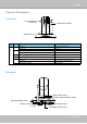
VIVOTEK Physical Description Front panel Lens and Manual Focus Ring Antenna (PT8133W) Status LED LED Definitions Item LED status Description 1 Steady Red Power on and system boot Red LED off Power off Blink Green every 1 sec. + Steady Red Network connected (heartbeat) Green LED off + Steady Red Network failed Blink Red every 0.15 sec. + Blink Green every 1 sec. Upgrading firmware 2 3 4 Blink Red every 0.15 sec. + Blink Green every 0.15 sec.
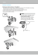
VIVOTEK Hardware Installation Mounting the Network Camera - Ceiling Mount 1. Use the holes on the mount bracket as a template to mark where holes will be drilled on the ceiling. Drill two holes into the ceiling; and hammer in the plastic anchors. 2. Attach the Network Camera to the mount bracket using two flathead screws. 3. Secure mount bracket to the ceiling using two panhead screws. 4. You can now proceed with cabling.
VIVOTEK Mounting the Network Camera - Wall Mount 1. Use the holes on the mount bracket as a template to mark where holes will be drilled on the ceiling. Drill two holes into the wall; and hammer in the plastic anchors. 2. Secure mount bracket to the wall using two included panhead screws. 3. Attach the Network Camera to the mount bracket using two flathead screws. 4. You can now proceed with cabling.
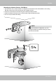
VIVOTEK NOTE: ► Keep away from interference source to make sure performance integrate, and avoid snow or moiré patterning. Hardware Reset ETHERNET WPS 12V 1.5A The reset button is used to reset the camera or restore the factory default settings. Sometimes resetting the system can return the camera to normal operation. If the system problems remain after rebooting, restore the factory default settings. Reset: Press and release the recessed reset button with a straightened paper clip.
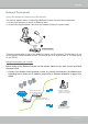
VIVOTEK Network Deployment Setup the Network Camera over the Internet This section explains how to configure the Network Camera over an Internet connection. 1. Connect the camera to a switch via Ethernet cable. 2. Connect the supplied power cable from the Network Camera to a power outlet. 2 12V 1.5A ETHERNET 1 POWER COLLISION 1 2 3 4 Ethernet Switch LINK RECEIVE PARTITION 5 There are several ways to set up the Network Camera over the Internet.
VIVOTEK 2. In this case, if the Local Area Network (LAN) IP address of your Network Camera is 192.168.0.3, please forward the following ports for the Network Camera on the router. ■ HTTP port ■ RTSP port ■ RTP port for audio ■ RTCP port for audio ■ RTP port for video ■ RTCP port for video If you have changed the port numbers on the Network page, please open the ports accordingly on your router. For information on how to forward ports on the router, please refer to your router’s user’s manual. 3.
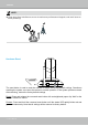
VIVOTEK Set up the Network Camera through Power over Ethernet (PoE) (PT8133) When using a PoE-enabled switch The Network Camera is PoE-compliant, which allows it to be powered via a single Ethernet cable. If your switch/router supports PoE, refer to the following illustration to connect the Network Camera to a PoE-enabled switch/router. power + data transmission ET ETHERN 12V 1.
VIVOTEK Software Installation Installation Wizard 2 (IW2), free-bundled software included on the product CD, helps you set up your Network Camera on the LAN. 1. Install IW2 from the Software Utility directory on the software CD. Double click the IW2 shortcut on your desktop to launch the program. 2. The program will conduct an analysis of your network environment. After your network environment is analyzed, please click Next to continue the program. 3.
VIVOTEK Configure the Wireless Connection (PT8133W) 1. Make sure your AP (Access Point) and Operating System support the WPS (Wi-Fi Protected Setup) functions. WPS enables easy setup with compatible APs. 2. Connect your camera using a LAN cable, open a web console, and enter the Configuration -> Wireless page. Select the WPS checkbox, and click the Save button. 3. The camera's blue LED should start flashing. Press and hold down both of the WPS buttons on your AP and your camera for at least 1 second.
VIVOTEK NOTE: 1. WPS may not work if your AP is configured with a "hidden" SSID. 2. If the camera can not detect an AP after 2 minutes, the wireless setup will be cancelled. 3. If a camera is assigned with a fixed IP outside the AP's network segment, wireless setup will fail. 4. A wired connection always has a higher priority. Unplug the LAN cable at an appropriate time for the wireless setup to take effect. 5.
VIVOTEK Accessing the Network Camera This chapter explains how to access the Network Camera through web browsers, RTSP players, 3GPP-compatible mobile devices, and VIVOTEK recording software. Using Web Browsers Use Installation Wizard 2 (IW2) to access to the Network Cameras installed on the LAN. If your network environment is not the LAN, follow these steps to access the Network Camera: 1. Launch your web browser (e.g., Microsoft® Internet Explorer or Mozilla Firefox). 2.
VIVOTEK ► By default, the Network Camera is not password-protected. To prevent unauthorized access, it is highly recommended to set a password for the Network Camera. For more information about how to enable password protection, please refer to Security on page 35. ► If you see a dialog box indicating that your security settings prohibit running ActiveX ® Controls, please enable the ActiveX ® Controls for your browser. 1. Choose Tools > Internet Options > Security > Custom Level. 2.
VIVOTEK IMPORTANT! • Currently the Network Camera utilizes 32-bit ActiveX plugin. You CAN NOT open a management/view session with the camera using a 64-bit IE browser. • If you encounter this problem, try execute the Iexplore.exe program from C:\ Windows\SysWOW64. A 32-bit version of IE browser will be installed. • On Windows 7, the 32-bit explorer browser can be accessed from here: C:\Program Files (x86)\Internet Explorer\iexplore.
VIVOTEK Using RTSP Players To view the MPEG-4 streaming media using RTSP players, you can use one of the following applications that support RTSP streaming. Quick Time Player Real Player VLC media player 1. Launch the RTSP player. mpegable Player 2. Choose File > Open URL. A URL dialog box will pop up. 3.
VIVOTEK Using 3GPP-compatible Mobile Devices To view the streaming media through 3GPP-compatible mobile devices, make sure the Network Camera can be accessed over the Internet. For more information on how to set up the Network Camera over the Internet, please refer to Setup the Network Camera over the Internet on page 9. To utilize this feature, please check the following settings on your Network Camera: 1.
VIVOTEK Using VIVOTEK Recording Software The product software CD also contains VIVOTEK’s recording software, ST-7501, allowing simultaneous monitoring and video recording for multiple Network Cameras. Please install the recording software, then launch the program to add the Network Camera to the Channel list. For detailed information about how to use the recording software, please refer to the user’s manual of the software or download the manual from http://www.vivotek.com.
VIVOTEK Main Page This chapter explains the layout of the main page. It is composed of the following sections: VIVOTEK INC. Logo, Host Name, Camera Control Area, PTZ Control Panel, Configuration Area, and Live video window. VIVOTEK INC. Logo Host Name Camera Control Area PTZ Control Panel Live View Window Configuration Area VIVOTEK INC. Logo Click this logo to visit the VIVOTEK website. Host Name The host name can be customized to fit your needs.
VIVOTEK Home, the camera starts panning from the current position to the left-most position, then to the rightmost position, and finally backward to the original position. When the current position is on the right side of Home, the camera starts panning from the current position to the right-most position, then to the leftmost position, and finally backward to the original position. Stop: Click this button to stop the Auto Pan and Auto Patrol functions.
VIVOTEK Joystick Settings Enable Joystick Connect to the USB plug of the joystick to a USB port on your management computer. Supported by the plug-in in the main page (Microsoft’s DirectX), once the plug-in in the main page is loaded, it will automatically detect if there is any joystick on the computer. The joystick should work properly without installing any other driver or software. Then you can begin to configure the joystick settings of connected devices.
VIVOTEK Buttons Configuration In Button Configuration window, the left column shows the actions you can assign, and the right column shows the functional buttons and assigned actions. The number of buttons may differ from different joysticks. Please follow the steps below to configure your joystick buttons: 1. Choosing one of the actions and click Assign will pop up a dialog. Then you can assign this action to a button by pressing the joystick button or select it from the drop-down list.
VIVOTEK 3. The Assigned Action will appear beside Button 1 in the right column as shown in the following diagram. Note that a button can only be assigned with an action. If you want to modify the settings, select the action on the list and click Clear Selected. 4. If you want to assign additional actions, repeat step a.~c. When all settings are complete, click OK to save the settings or click Cancel to discard the settings.
VIVOTEK 5. Click OK to save the settings or click Cancel to discard the settings. NOTE: • • • If you want to assign Preset actions to your joystick, the preset locations should be configured in advance. If your joystick is not working properly, it may need to be calibrated. Click the Calibrate button to open the Game Controllers window located in Microsoft Windows control panel and follow the instructions for trouble shooting.
VIVOTEK Configuration Area Client Settings: Click this button to access the client settings page. For more information, please refer to Client Settings on page 30. Configuration: Click this button to access the configuration page of the Network Camera. It is suggested that a password be applied to the Network Camera so that only the administrator can configure the Network Camera. For more information, please refer to Configuration on page 32.
VIVOTEK Digital Zoom: Click and uncheck “Disable digital zoom” to enable the zoom operation. The navigation screen indicates the part of the image being magnified. To control the zoom level, drag the slider bar. To move to a different area you want to magnify, drag the navigation screen image. Pause: Pause the transmission of the streaming media. The button becomes the after clicking the Pause button. Stop: Stop the transmission of the streaming media. Click the transmission.
VIVOTEK ■ The following window is displayed when the video mode is set to MJPEG: Video Title Title and Time Time Video 10:17:38 2011/12/14 Video Control Buttons Drop-down List of Preset Positions Video Title: The video title can be configured. For more information, please refer to Video Settings on page 68. Time: Display the current time. For more information, please refer to Video Settings on page 68. Title and Time: The video title and time can be stamped on the streaming video.
VIVOTEK Client Settings This chapter explains how to select the stream transmission mode and saving options on the local computer. When finished with the settings on this page, click Save on the bottom of the page to enable the settings. H.264/MPEG-4 Media Options Select whether to stream video or audio data or both. This is enabled only when the video mode is set to H.264 or MPEG-4. H.264/MPEG-4 Protocol Options Depending on your network environment, there are four transmission modes for H.
VIVOTEK MP4 Saving Options Users can record live video as they are watching by clicking Here, you can specify the storage destination and file name. Start MP4 Recording on the main page. Folder: Specify the storage destination for the recorded video files. File name prefix: Enter the text that will be appended to the front of the video file name. Add date and time suffix to the file name: Select this option to append the date and time to the end of the file name.
VIVOTEK Configuration Click Configuration on the main page to enter the camera setting pages. Note that only Administrators can access the configuration page. VIVOTEK offers an easy-to-use user interface that helps you set up your network camera with minimal effort. To simplify the setting procedure, two types of user interfaces are available: Advanced Mode for professional users and Basic Mode for entry-level users.
VIVOTEK Advanced Mode Configuration list Click to switch to Basic mode Firmware Version Each function on the configuration list will be explained in the following sections. Those functions that are displayed only in Advanced Mode are marked with Advanced Mode . If you want to set up the advanced functions, please click [Advanced Mode] on the bottom of the configuration list to quickly switch over.
VIVOTEK System Time Keep current date and time: Select this option to preserve the current date and time of the Network Camera. The Network Camera’s internal real-time clock maintains the date and time even when the system power is turned off. Synchronize with computer time: Select this option to synchronize the date and time of the Network Camera with the local computer. The read-only date and time of the PC is displayed when updated. Manual: The administrator can enter the date and time manually.
VIVOTEK Security This section explains how to enable password protection and create multiple accounts. Root Password The administrator account name is “root”, which is permanent and can not be deleted. If you want to add more accounts in the Manage User column, please set a password for the “root” account first. 1. Type the password in both text boxes, then click Save to enable password protection. 2.
VIVOTEK HTTPS (Hypertext Transfer Protocol over SSL) Advanced Mode This section explains how to enable authentication and encrypted communication over SSL (Secure Socket Layer). It helps protect streaming data transmission over the Internet on higher security level. Enable HTTPS Check this item to enable HTTPS communication, then select a connection option: "HTTP & HTTPS" or "HTTPS only". Note that you have to create and install a certificate first in the second column before clicking the Save button.
VIVOTEK 4. The Certificate Information will automatically be displayed in the third column as shown below. You can click Property to view detailed information about the certificate. 5. Click Home to return to the main page. Change the address from “http://” to “https://“ in the address bar and press Enter on your keyboard. Some Security Alert dialogs will pop up. Click OK or Yes to enable HTTPS. https:// https://192.168.5.151/index.
VIVOTEK Create self-signed certificate manually 1. Select this option. 2. Click Create to open a Create Certificate page, then click Save to generate the certificate. 3. The Certificate Information will automatically be displayed in the third column as shown below. You can click Property to see detailed information about the certificate. Create certificate request and install : Select this option if you want to create an official certificate issued by a CA (Certificate Authority). 1. Select this option.
VIVOTEK 3. If you see the following Information bar, click OK and click on the Information bar on the top of the page to allow pop-ups. 4. The pop-up window shows an example of a certificate request.
VIVOTEK 5. Look for a trusted certificate authority that issues digital certificates. Enroll the Network Camera. Wait for the certificate authority to issue a SSL certificate; click Browse... to search for the issued certificate, then click Upload in the second column. NOTE: ► How do I cancel the HTTPS settings? 1. Uncheck Enable HTTPS secure connection in the first column and click Save; a warning dialog will pop up. 2. Click OK to disable HTTPS. 3.
VIVOTEK SNMP (Simple Network Management Protocol) Advanced Mode This section explains how to use the SNMP on the network camera. The Simple Network Management Protocol is an application layer protocol that facilitates the exchange of management information between network devices. It helps network administrators to remotely manage network devices and find, solve network problems with ease. ■ The SNMP consists of the following three key components: 1.
VIVOTEK Network This section explains how to configure a wired network connection for the Network Camera. Network Type LAN Select this option when the Network Camera is deployed on a local area network (LAN) and is intended to be accessed by local computers. The default setting for the Network Type is LAN. Rememer to click Save when you complete the Network setting.
VIVOTEK UPnPTM component is installed on your computer. Network Camera (192.168.5.151) Enable UPnP port forwarding: To access the Network Camera from the Internet, select this option to allow the Network Camera to open ports on the router automatically so that video streams can be sent out from a LAN. To utilize of this feature, make sure that your router supports UPnPTM and it is activated.
VIVOTEK ► Following are the steps to enable the UPnP TM user interface on your computer: Note that you must log on to the computer as a system administrator to install the UPnP TM components. 1. Go to Start, click Control Panel, then click Add or Remove Programs. 2. In the Add or Remove Programs dialog box, click Add/Remove Windows Components. 3. In the Windows Components Wizard dialog box, select Networking Services and click Details.
VIVOTEK 4. In the Networking Services dialog box, select Universal Plug and Play and click OK. 5. Click Next in the following window. 6. Click Finish. UPnP TM is enabled. ► How does UPnP TM work? UPnP TM networking technology provides automatic IP configuration and dynamic discovery of devices added to a network. Services and capabilities offered by networked devices, such as printing and file sharing, are available among each other without the need for cumbersome network configuration.
VIVOTEK Enable IPv6 Select this option and click Save to enable IPv6 settings. Please note that this only works if your network environment and hardware equipment support IPv6. The browser should be Microsoft® Internet Explorer 6.5, Mozilla Firefox 3.0 or above. When IPv6 is enabled, by default, the network camera will listen to router advertisements and be assigned with a link-local IPv6 address accordingly. IPv6 Information: Click this button to obtain the IPv6 information as shown below.
VIVOTEK Please follow the steps below to link to an IPv6 address: 1. Open your web browser. 2. Enter the link-global or link-local IPv6 address in the address bar of your web browser. 3. The format should be: http://[2001:0c08:2500:0002:0202:d1ff:fe04:65f4]/ IPv6 address 4. Press Enter on the keyboard or click Refresh button to refresh the webpage.
VIVOTEK IEEE 802.1x Advanced Mode Enable this function if your network environment uses IEEE 802.1x, which is a port-based network access control. The network devices, intermediary switch/access point/hub, and RADIUS server must support and enable 802.1x settings. The 802.1x standard is designed to enhance the security of local area networks, which provides authentication to network devices (clients) attached to a network port (wired or wireless).
VIVOTEK 3. When all settings are complete, move the Network Camera to the protected LAN by connecting it to an 802.1x enabled switch. The devices will then start the authentication automatically. NOTE: ► The authentication process for 802.1x: 1. The Certificate Authority (CA) provides the required signed certificates to the Network Camera (the supplicant) and the RADIUS Server (the authentication server). 2. A Network Camera requests access to the protected LAN using 802.
VIVOTEK Network > QoS (Quality of Service) Advanced Mode Quality of Service refers to a resource reservation control mechanism, which guarantees a certain quality to different services on the network. Quality of service guarantees are important if the network capacity is insufficient, especially for real-time streaming multimedia applications. Quality can be defined as, for instance, a maintained level of bit rate, low latency, no packet dropping, etc.
VIVOTEK QoS/DSCP (the DiffServ model) DSCP-ECN defines QoS at Layer 3 (Network Layer). The Differentiated Services (DiffServ) model is based on packet marking and router queuing disciplines. The marking is done by adding a field to the IP header, called the DSCP (Differentiated Services Codepoint). This is a 6-bit field that provides 64 different class IDs. It gives an indication of how a given packet is to be forwarded, known as the Per Hop Behavior (PHB).
VIVOTEK Network > HTTP Advanced Mode To utilize HTTP authentication, make sure that your have set a password for the Network Camera first; please refer to Security on page 35 for details. Authentication: Depending on your network security requirements, the Network Camera provides two types of security settings for an HTTP transaction: basic and digest. If basic authentication is selected, the password is sent in plain text format and there can be potential risks of being intercepted.
VIVOTEK URL command -- http://:/ For example, when the Access name for stream 2 is set to video2.mjpg: 1. Launch Mozilla Firefox or Netscape. 2. Type the URL command in the address bar. Press Enter. 3. The JPEG images will be displayed in your web browser. http://192.168.5.151/video2.
VIVOTEK FTP The FTP server allows the user to save recorded video clips. You can utilize VIVOTEK Installation Wizard 2 to upgrade the firmware via FTP server. By default, the FTP port is set to 21. It can also be assigned to another port number between 1025 and 65535. RTSP Streaming To utilize RTSP streaming authentication, make sure that you have set a password for the Network Camera first; please refer to Security on page 35 for details.
VIVOTEK The availability of the RTSP streaming for the three authentication modes is listed in the following table: Disable Basic Digest Quick Time player Real Player O O O O O X Access name for stream 1 / stream 2 / stream 3: This Network camera supports three simultaneous video streams. The access name is used to differentiate the streaming source. If you want to use an RTSP player to access the Network Camera, you have to set the video mode to H.
VIVOTEK RTSP port /RTP port for video, audio/ RTCP port for video, audio ■ RTSP (Real-Time Streaming Protocol) controls the delivery of streaming media. By default, the port number is set to 554. ■ The RTP (Real-time Transport Protocol) is used to deliver video and audio data to the clients. By default, the RTP port for video is set to 5556 and the RTP port for audio is set to 5558.
VIVOTEK Wireless (PT8133W only) Manual Configuration: Setting up wireless cameras’ connections can be tricky. The configuration process involves hardwire connection to your LAN for initial setup and wireless connection to AP. To switch between the connection types, you have to physically disconnect the 12VDC connector. For example, when you are finished with initial setup via LAN, you have to remove the RJ-45 LAN cable and disconnect the 12VDC power jack, and then reconnect the power.
VIVOTEK 3. Attach a LAN cable between your wireless camera and router/switch. Use the IW2 utility in the product CD to locate the camera in LAN. Double-click on the IP address to start an IE session with the camera. 4. Enter the Configuration > Wireless menu, and enter the name (SSID) of the existing wireless network, channel number, and other related information. See the following pages for more details. You may enter the Configuration > Network page to setup DHCP or static IP if necessary. 5.
VIVOTEK Manual SSID (Service Set Identifier): This is the name that identifies a wireless network. Access Points and wireless clients attempting to connect to a specific WLAN (Wireless Local Area Network) must use the same SSID. The default setting is “default”. Note: The maximum length for an SSID is 32 single-byte characters and cannot consist of “, <, >, or blank spaces. Note that the SSID is case-sensitive.
VIVOTEK 2. WEP (Wired Equivalent Privacy): This allows communication only with other devices with identical WEP settings. ■ Authentication Mode: Choose one of the following modes. The default setting is “Open”. Open – Communicates the key across the network. Shared – Allows communication only with other devices with identical WEP settings. ■ Key length: The administrator can set the key length to 64 or 128 bits. The default setting is “64 bits”. ■ Key format: Hexadecimal or ASCII.
VIVOTEK 3. WPA-PSK: Use WPA (Wi-Fi Protected Access) pre-shared key. More secure than WEP, the Wi-Fi Alliance developed WPA (Wi-Fi Protected Access) in 2003 to address WEP’s weaknesses. Improvements included TKIP, which changes the encryption key for each data transmission. ■ Algorithm: Choose one of the following algorithms for WPA-PSK and WPA2-PSK modes. TKIP (Temporal Key Integrity Protocol): A security protocol used in IEEE 802.11 wireless networks.
VIVOTEK WPS: 1. Make sure your AP (Access Point) and Operating System support WPS (Wi-Fi Protected Setup) functions. WPS enables easy setup with compatible APs. 2. Connect your camera using a LAN cable, open a web console, and enter the Configuration -> Wireless page. Select the WPS checkbox, and click the Save button. 3. The camera's blue LED should start flashing. Press and hold down both of the WPS buttons on your AP and your camera for at least 1 second.
VIVOTEK DDNS This section explains how to configure the dynamic domain name service for the Network Camera. DDNS is a service that allows your Network Camera, especially when assigned with a dynamic IP address, to have a fixed host and domain name. DDNS: Dynamic domain name service Enable DDNS: Select this option to enable the DDNS setting. Provider: Select a DDNS provider from the provider drop-down list. VIVOTEK offers Safe100.net, a free dynamic domain name service, to VIVOTEK customers.
VIVOTEK [Register] Successfully Your account information has been mailed to registered e-mail address 4. Select Enable DDNS and click Save to enable the setting. ■ CustomSafe100 VIVOTEK offers documents to establish a CustomSafe100 DDNS server for distributors and system integrators. You can use CustomSafe100 to register a dynamic domain name if your distributor or system integrators offer such services. 1. In the DDNS column, select CustomSafe100 from the drop-down list. 2.
VIVOTEK Access List Advanced Mode This section explains how to control access permission by verifying the client PC’s IP address. General Settings Maximum number of concurrent streaming connection(s) limited to: Simultaneous live viewing for 1~10 clients (including stream #1, #2, and #3). The default value is 10. If you modify the value and click Save, all current connections will be disconnected and automatically attempt to re-link (IE Explore or Quick Time Player).
VIVOTEK ■ Refresh: Click this button to refresh all current connections. ■ Add to deny list: You can select entries from the Connection Status list and add them to the Deny List to deny access. Please note that those checked connections will only be disconnected temporarily and will automatically try to re-link again (IE Explore or Quick Time Player). If you want to enable the denied list, please check Enable access list filtering and click Save in the first column.
VIVOTEK Network: This rule allows the user to assign a network address and corresponding subnet mask to the Allow/Deny List. The IP address is written in the CIDR format. For example: IP address 192.168.2.x will be bolcked. Range: This rule allows the user to assign a range of IP addresses to the Allow/Deny List. This rule is only applied to IPv4. For example: ■ Delete Allowed/Denied list: In the Delete Allowed List or Delete Denied List column, make a selection and click Delete.
VIVOTEK Audio and Video This section explains how to cofigure the audio and video settings of the Network Camera. It is composed of the following two columns: Video Settings and Audio Settings. Video Settings Video title: Enter a name that will be displayed on the title bar of the live video. Video title Title and Time Video 10:00:27 2011/12/14 Color: Select to display color or black/white video streams.
VIVOTEK Note that when the frame size is set to 176 x 144 as shown in the picture below, only the time will be stamped on the video streams. Video 10:00:27 2011/12/14 Image Settings Advanced Mode Click Image Settings to open the Image Settings page. On this page, you can tune the White Balance, Brightness, Saturation, Contrast, and Sharpness for the video. White balance: Adjust the value for the best color temperature.
VIVOTEK 2. Place a sheet of paper of white or cooler color temperature, such as blue, in front of the lens, then allow the Network Camera to adjust the color temperature automatically. 3. Select Keep current value, and click the Save button to preserve current configuration. Image Adjustment ■ Brightness: Adjust the image brightness level, which ranges from -5 to +5. The default value is set to 0. ■ Saturation: Adjust the image saturation level, which ranges from -5 to +5. The default value is set to 0.
VIVOTEK Sensor Settings Advanced Mode Click Sensor settings to open the Sensor Settings page. On this page, you can set the Maximum Exposure Time, Exposure level, BLC settings, and an image profile for a different period of time. Maximum Exposure Time: The default iris setting of the sensor is fixed mode, and the AES option will be 1/30. There are several options for AES: 1/5, 1/15, 1/30, 1/60, 1/120, 1/240, and 1/480 second.
VIVOTEK If you want to configure another sensor setting for day/night/schedule mode, please click the Profile button to open the Profile Settings window as shown below. Please follow the steps below to setup a profile: 1. Check Enable this profile. 2. Select the applied mode: Day mode, Night mode, or Schedule mode. Please manually enter a range of time if you choose Schedule mode. 3. Configure the settings in the following columns. Please refer to the previous page for detailed information. 4.
VIVOTEK Viewing Window Advanced Mode Click Viewing Window to open the viewing region settings page. On this page, you can set the Region of Interest and the Output Frame Size for stream 1 ~ 3. Please follow the steps below to set up those settings for a stream: 1. Select a stream which you want to set up the viewing region. If you want to stream out the video to a mobile device, please select stream 3. 2. Select a Region of Interest from the drop-down list. The floating frame, will resize accordingly.
VIVOTEK Video quality settings for multiple streams Advanced Mode The Network Camera offers three choices of video compression standards for real-time viewing: MPEG4, H.264, and MJPEG. Click the items to display the detailed configuration settings. You can set up three seperate streams for the Network Camera for different viewing devices.
VIVOTEK On the other hand, if Fixed quality is selected, all frames are transmitted with the same quality; bandwidth utilization is therefore unpredictable. The video quality can be adjusted to the following settings: Medium, Standard, Good, Detailed, and Excellent. You can also select Customize and manually enter a value. The H.264 mode has similar settings with that of the MPEG-4 mode as previously mentioned, yet it offers a higher compression rate for saving storage and network bandwidth.
VIVOTEK Audio Settings Mute: Select this option to disable audio transmission from the Network Camera to all clients. Note that if mute mode is turned on, no audio data will be transmitted even if audio transmission is enabled on the Client Settings page. In that case, the following message is displayed: Internal microphone input gain: Select the gain of the internal audio input according to ambient conditions. Adjust the gain from +21 db (most sensitive) ~ -33 db (least sensitive).
VIVOTEK Motion Detection This section explains how to configure the Network Camera to enable motion detection. A total of three motion detection windows can be configured. Video(TCP-AV) Follow the steps below to enable motion detection: 1. Click New to add a new motion detection window. 2. In the Window Name text box, enter a name for the motion detection window. ■ To move and resize the window, drag and drop your mouse on the window. ■ To delete window, click X on the top right corner of the window. 3.
VIVOTEK A green bar indicates that even though motions have been detected, the event has not been triggered because the image variations still fall under the defined threshold. Percentage = 30% NOTE: ► How does motion detection work? A C B D There are two motion detection parameters: Sensitivity and Percentage. In the illustration above, frame A and frame B are two sequential images.
VIVOTEK Motion Detection Profile You may create additional Motion Detection profile for different application scenarios, e.g., a different setting for the off-office hours. Configure the period of time during which this profile will apply. Set up a detection window, and then click the Save button and the Close button to finish the configuration. The Motion Detection takes effect even when it is panning or patrolling through points of interest in its surveillance area.
VIVOTEK Camera Control This section explains how to control the Network Camera’s Pan/Tilt/Zoom/Focus operation via the control panel and how to create preset positions. Preset Locations On this page, you can create preset positions for the Network Camera to go to directly or patrol consecutively from one position to another. A total of 128 preset positions can be configured. Please follow the steps below to create preset positions: 1.
VIVOTEK Patrol Settings You can select preset locations to arange the patrolling tour for the Network Camera. Please follow the steps below to set up a patrolling tour: 1. Click to select one or multiple preset locations by checking their checkboxes. 2. Click the >> (Move) button to move them to the Patrol locations column. 3. Click to select a position, and manually enter a Dwelling time for the camera to stay during an auto patrol. The default value is 5 seconds. 4.
VIVOTEK Return to Home Position while Idle If you select this option, the Network Camera will automatically return to the home position after idling for a specific time span. Please remember to click Save to enable the settings. ■ The Preset Locations will be displayed on the Home page: ■ Click Go to: The Network Camera will move to the preset location. ■ Click Patrol: The Network Camera will patrol among the selected preset positions (from right to left) for once.
VIVOTEK Homepage Layout Advanced Mode This section explains how to set up your own customized homepage layout. Preview This column shows the settings of your homepage layout. You can manually select the background and font colors in Theme Options, the third column on this page. The settings will automatically show up in this Preview field. The following shows the homepage using the default settings: ■ Hide Powered by VIVOTEK: If you check this item, it will be removed from the homepage.
VIVOTEK Theme Options Here you can change the color of your homepage layout. There are three types of preset patterns for you to choose from. The new layout will simultaneously appear in the Preview filed. Click Save to enable the settings.
VIVOTEK ■ Follow the steps below to set up the customed homepage: 1. Click Custom on the left column. 2. Click the field where you want to change the color on the right column. Color Selector Custom Pattern 3. The palette window will pop up as shown below. 5 4 6 4. Drag the slider bar and/or click on the left square to select a desired color. 5. The selected color will show up in the corresponding fields and in the Preview column. 6. Click Save to enable the settings.
VIVOTEK Application Advanced Mode This section explains how to configure the Network Camera to react in response to particular situations (event). A typical application is that when a motion is detected, the Network Camera sends buffered images to a FTP server or e-mail address as notifications. In the illustration on the right, an event can be triggered Action Event Trigger by many sources, such as motion detection or external (what to do) digital input devices. When an event is triggered, you ex.
VIVOTEK Event Settings In the Event Settings column, click Add to open the Event Settings page. On this page, you can arrange three elements -- Trigger, Schedule, and Action to set an event. A total of 3 event settings can be configured. Event name: Enter a name for the event setting. Enable this event: Select this option to enable the event setting. Priority: Select the relative importance of this event (High, Normal, or Low). Events with a higher priority setting will be executed first.
VIVOTEK An event is an action initiated by a user-defined trigger source; it is the causal arrangement of the following three elements: Trigger, Event Schedule, and Action. Trigger This is the cause or stimulus which defines when to trigger the Network Camera. The trigger source can be configured to use the Network Camera’s built-in motion detection mechanism. There are several choices of trigger sources as shown below. Select the items to display the detailed configuration options.
VIVOTEK Event Schedule Specify the period for the event. ■ Select the days of the week. For example, some detection might not need to be applied during the office hours, while they are necessary during the off-office hours. ■ Select the recording schedule in 24-hr time format. Action Define the actions to be performed by the Network Camera when an event is triggered. ■ Move to preset location Select this option, the Network Camera will move to the preset location when a trigger is activated.
VIVOTEK Here is an example of Event Settings page: When completed, click Save to enable the settings and click Close to exit Event Settings page. The new event settings / server settings / media settings will appear in the event drop-down list on the Application page.
VIVOTEK Here is an example of Application page with an event setting: When the Event Status is ON, once an event is triggered by motion detection, the Network Camera will automatically send snapshots via e-mail. If you want to stop the event trigger, you can click ON to turn it to OFF status or click Delete to remove the event setting. To remove a server setting from the list, select a server name from the drop-down list and click Delete.
VIVOTEK Server Settings Click the Add Server button on Event Settings page to open the Server Setting page. On this page, you can specify where the notification messages are sent when a trigger is activated. A total of 5 server settings can be configured. Server name: Enter a name for the server setting. Server Type There are four choices of server types available: Email, FTP, HTTP, and Network storage. Select the item to display the detailed configuration options.
VIVOTEK FTP: Select to send the media files to an FTP server when a trigger is activated. ■ Server address: Enter the domain name or IP address of the FTP server. ■ Server port By default, the FTP server port is set to 21. It can also be assigned to another port number between 1025 and 65535. ■ User name: Enter the login name of the FTP account. ■ Password: Enter the password of the FTP account. ■ FTP folder name Enter the folder where the media file will be placed.
VIVOTEK HTTP: Select to send the media files to an HTTP server when a trigger is activated. ■ URL: Enter the URL of the HTTP server. ■ User name: Enter the user name if necessary. ■ Password: Enter the password if necessary. To verify if the HTTP settings are correctly configured, click Test. The result will be shown in a pop-up window as below. If successful, you will receive a test.txt file on the HTTP server. Click Save to enable the settings, then click Close to exit the page.
VIVOTEK Media Settings Click Add Media on the Event Settings page to open the Media Settings page. On this page, you can specify the type of media that will be sent when a trigger is activated. A total of 5 media settings can be configured. Media name: Enter a name for the media setting. Media Type There are three choices of media types available: Snapshot, Video clip, and System log. Select the item to display the detailed configuration options. You can configure either one or all of them.
VIVOTEK Video clip: Select to send video clips when a trigger is activated. ■ Source: Select to record video clips from stream 1 or stream 2. ■ Pre-event recording The Network Camera has a buffer area; it temporarily holds data up to a certain limit. Enter a number to decide the duration of recording before a trigger is activated. Up to 9 seconds can be set. ■ Maximum duration Specify the maximum recording duration in seconds. Up to 10 seconds can be set.
VIVOTEK When completed, click Save to enable the settings and click Close to exit this page. The new media settings will appear on the Event Settings page. You can continue to select a server and media type for the event. ■ Create folders by date, time, and hour automatically: If you check this item, the system will generate folders automatically by date. ■ View: Click this button to open a file list window. This function is only available when a Networked Storage is applied.
VIVOTEK Click 20111120 to open the directory: The format is: HH (24r) Click to open the file list for that hour 2011 2011 Click to go back to the previous level of the directory Click to delete selected items Click to delete all recorded data 2011 2011 The format is: File name prefix + Minute (mm) You can set up the file name prefix on Media Settings page. Please refer to page 95 for detailed information.
VIVOTEK Recording Advanced Mode This section explains how to configure the recording settings for the Network Camera. Recording Settings NOTE: ► Before setting up this page, please set up the Network Storage on the Server Settings (Add Server) page first. Network Storage Setting Click Server on the message bar to open the Server Settings page (if you have not) and follow the steps below to set up: 1. Fill in the information for your server.
VIVOTEK If successful, you will receive a test.txt file on the network storage share. 3. Enter a server name. 4. Click Save to complete the settings and click Close to exit the page. Recording Settings Click Add to open the recording setting page. On this page, you can define the recording source, recording schedule and recording capacity. A total of 2 recording settings can be configured. Recording name: Enter a name for the recording setting.
VIVOTEK With adaptive recording: Select this option will activate the frame rate control according to alarm trigger. The frame control means that when there is a triggered alarm/event, the frame rate will raise up to the value you’ve set on the Stream setting page. Please refer to page 74 for more information. .
VIVOTEK Trigger: Select the trigger of recording action either as a planned schedule. Recording Schedule: ■ Select the days of the week. ■ Select the recording to be Always recording or starting and ending between two points in time in a 24hr format. Destination: You can select the network storage to store the recorded video files. Capacity: You can choose either the “entire free space” or “reserved space”.
VIVOTEK System Log Advanced Mode This section explains how to configure the Network Camera to send the system log to the remote server as backup. Remote Log You can configure the Network Camera to send the system log file to a remote server as a log backup. Before utilizing this feature, it is suggested that the user install a log-recording tool to receive system log messages from the Network Camera. An example is Kiwi Syslog Daemon. Visit http://www.kiwisyslog. com/kiwi-syslog-daemon-overview/.
VIVOTEK View Parameters Advanced Mode The View Parameters page lists the entire system’s parameters in alphabetical order. If you need technical assistance, please provide the information listed on this page.
VIVOTEK Maintenance This chapter explains how to restore the Network Camera to factory default, upgrade firmware version, etc. Reboot This feature allows you to reboot the Network Camera, which takes about one minute to complete. When completed, the live video page will be displayed in your browser. The following message will be displayed during the rebooting process.
VIVOTEK Export / Upload Files Advanced Mode This feature allows you to Export / Upload daylight saving time rules, custom language files, and setting backup files. Export daylight saving time configuration file: Click to set the start and end time of DST. Follow the steps below to export: 1. In the Export files column, click Export to export the daylight saving time configuration file from the Network Camera. 2. A file download dialog will pop up as shown below.
VIVOTEK Upload daylight saving time rule: Click Browse… and specify the XML file to upload. If the incorrect date and time are assigned, you will see the following warning message when uploading the file to the Network Camera. The following message is displayed when attempting to upload an incorrect file format. Export language file: Click to export language strings. VIVOTEK provides nine languages: English, Deutsch, Español, Français, Italiano, 日本語 , Português, 簡体中文 , and 繁體中文 .
VIVOTEK The following message is displayed when the upgrade has succeeded. Reboot system now!! This connection will close. The following message is displayed when you have selected an incorrect firmware file. Starting firmware upgrade... Do not power down the server during the upgrade. The server will restart automatically after the upgrade is completed. This will take about 1 - 5 minutes.
VIVOTEK Appendix URL Commands for the Network Camera 1. Overview For some customers who already have their own web site or web control application, the Network Camera/Video Server can be easily integrated through URL syntax. This section specifies the external HTTP-based application programming interface. The HTTP-based camera interface provides the functionality to request a single image, control camera functions (PTZ, output relay etc.), and get and set internal parameter values.
VIVOTEK 3. General CGI URL Syntax and Parameters CGI parameters are written in lower-case and as one word without any underscores or other separators. When the CGI request includes internal camera parameters, these parameters must be written exactly as they are named in the camera or video server. The CGIs are organized in functionally-related directories under the cgi-bin directory. The file extension .cgi is required. Syntax: http:///cgi-bin/[/...]/.
VIVOTEK 4. Security Level SECURITY LEVEL SUB-DIRECTORY DESCRIPTION 0 anonymous Unprotected. 1 [view] anonymous, viewer, 1. Can view, listen, talk to camera. dido, camctrl 4 [operator] anonymous, viewer, dido, camctrl, operator 6 [admin] anonymous, viewer, dido, camctrl, 2. Can control DI/DO, PTZ of the camera. Operator access rights can modify most of the camera’s parameters except some privileges and network options. Administrator access rights can fully control the camera’s operations.
VIVOTEK 5. Get Server Parameter Values Note: The access right depends on the URL directory. Method: GET/POST Syntax: http:///cgi-bin/anonymous/getparam.cgi?[] [&…] http:///cgi-bin/viewer/getparam.cgi?[] [&…] http:///cgi-bin/operator/getparam.cgi?[] [&…] http:///cgi-bin/admin/getparam.cgi?[] [&…] Where the should be [_] or [.].
VIVOTEK Response: HTTP/1.0 200 OK\r\n Content-Type: text/html\r\n Context-Length: 33\r\n \r\n network.ipaddress=192.168.0.
VIVOTEK 6. Set Server Parameter Values Note: The access right depends on the URL directory. Method: GET/POST Syntax: http:///cgi-bin/anonymous/setparam.cgi? = [&=…][&update=][&return=] http:///cgi-bin/viewer/setparam.cgi? = [&=…][&update=] [&return=] http:///cgi-bin/operator/setparam.
VIVOTEK [] Only the parameters that you set and are readable will be returned. Example: Set the IP address of server to 192.168.0.123: Request: http://myserver/cgi-bin/admin/setparam.cgi?network_ipaddress=192.168.0.123 Response: HTTP/1.0 200 OK\r\n Content-Type: text/html\r\n Context-Length: 33\r\n \r\n network.ipaddress=192.168.0.
VIVOTEK 7. Available parameters on the server Valid values: VALID VALUES DESCRIPTION string[] Text strings shorter than ‘n’ characters. The characters “,’, <,>,& are invalid. string[n~m] Text strings longer than `n’ characters and shorter than `m’ characters. The characters “,’, <,>,& are invalid. password[] The same as string but displays ‘*’ instead. integer Any number between (-231 – 1) and (231 – 1). positive integer Any number between 0 and (232 – 1).
VIVOTEK 7.1System Group: system NAME VALUE DEFAULT SECURITY DESCRIPTION (get/set) hostname string[40] Wireless Network Camera, Video Server, Wireless Video Server). ledoff 0 6/6 Turn on (0) or turn off (1) all led indicators. date , keep, Current date of system. Set to ‘keep’ auto to keep date unchanged. Set to ‘auto’ to use NTP to synchronize date.
VIVOTEK Midway Island, Samoa -400: GMT-10:00 Hawaii -360: GMT-09:00 Alaska -320: GMT-08:00 Las Vegas, San_Francisco, Vancouver -280: GMT-07:00 Mountain Time, Denver -281: GMT-07:00 Arizona -240: GMT-06:00 Central America, Central Time, Mexico City, Saskatchewan -200: GMT-05:00 Eastern Time, New York, Toronto -201: GMT-05:00 Bogota, Lima, Quito, Indiana -180: GMT-04:30 Caracas -160: GMT-04:00 Atlantic Time, Canada, La Paz, Santiago -140: GMT-03:30 Newfoundland -120: GMT-03:00 Brasilia, Buenos Aires, Georgeto
VIVOTEK -40: GMT-01:00 Azores, Cape_Verde_IS. 0: GMT Casablanca, Greenwich Mean Time: Dublin, Edinburgh, Lisbon, London 40: GMT 01:00 Amsterdam, Berlin, Rome, Stockholm, Vienna, Madrid, Paris 41: GMT 01:00 Warsaw, Budapest, Bern 80: GMT 02:00 Athens, Helsinki, Istanbul, Riga 81: GMT 02:00 Cairo 82: GMT 02:00 Lebanon, Minsk 83: GMT 02:00 Israel 120: GMT 03:00 Baghdad, Kuwait, Riyadh, Moscow, St.
VIVOTEK Calcutta, Chennai, Mumbai, New Delhi 230: GMT 05:45 Kathmandu 240: GMT 06:00 Almaty, Novosibirsk, Astana, Dhaka, Sri Jayawardenepura 260: GMT 06:30 Rangoon 280: GMT 07:00 Bangkok, Hanoi, Jakarta, Krasnoyarsk 320: GMT 08:00 Beijing, Chongging, Hong Kong, Kuala Lumpur, Singapore, Taipei 360: GMT 09:00 Osaka, Sapporo, Tokyo, Seoul, Yakutsk 380: GMT 09:30 Adelaide, Darwin 400: GMT 10:00 Brisbane, Canberra, Melbourne, Sydney, Guam, Vladivostok 440: GMT 11:00 Magadan, Solomon Is.
VIVOTEK in time zone. daylight_dstactualmode 1 6/7 Check if current time is under daylight saving time. (Used internally) daylight_auto_begintime string[19] NONE 6/7 Display the current daylight saving start time. (product dependent) daylight_auto_endtime string[19] NONE 6/7 Display the current daylight saving end time. (product dependent) daylight_timezones updateinterval string 0, daylight saving time.
VIVOTEK “restoreexceptXYZ” commands. When cooperating with others, the system parameters will be restored to the default value except for a union of the combined results. restoreexceptdst N/A 7/6 Restore the system parameters to default values except all daylight saving time settings. This command can cooperate with other “restoreexceptXYZ” commands. When cooperating with others, the system parameters will be restored to default values except for a union of combined results.
VIVOTEK for a union of the combined results. 7.1.1 System.info Subgroup of system: info (The fields in this group are unchangeable.) NAME VALUE DEFAULT SECURITY DESCRIPTION (get/set) modelname string[40] extendedmodelname string[40]
VIVOTEK 7.2 Status Group: status NAME VALUE DEFAULT SECURITY DESCRIPTION (get/set) videoactualmodulation ntsc, pal vi_i0 1 4/7 The actual modulation type (videoin.type=0). 0 1/7 0 => Inactive, normal 1 => Active, triggered onlinenum_rtsp integer 0 6/7 Current number of RTSP connections. onlinenum_httppush integer 0 6/7 Current number of HTTP push server connections. eth_i0 1/7 Get network information from mii-tool. 7.
VIVOTEK 7.4 Network Group: network NAME VALUE DEFAULT SECURITY DESCRIPTION (get/set) type lan, lan 6/6 Network connection type. 6/6 Stop related process before setting pppoe preprocess 0~15 port value. resetip 1 6/6 1 => Get ipaddress, subnet, router, dns1, dns2 from DHCP server at next reboot. 0 => Use preset ipaddress, subnet, rounter, dns1, and dns2. ipaddress
VIVOTEK ca_size 0 6/7 CA file size (in bytes) certificate_exist 0 6/6 Certificate installed flag (for TLS) certificate_time 0 6/7 Certificate installed time. Represented in EPOCH certificate_size 0 6/7 Certificate file size (in bytes) privatekey_exist 0 6/6 Private key installed flag (for TLS) privatekey_time 0 6/7 Private key installed time.
VIVOTEK address setting. 7.5.4 FTP Subgroup of network: ftp NAME VALUE DEFAULT SECURITY DESCRIPTION (get/set) port 21, 1025~65535 21 6/6 Local ftp server port. 7.5.5 HTTP Subgroup of network: http NAME VALUE DEFAULT SECURITY DESCRIPTION (get/set) port 80, 1025 ~ 80 6/6 HTTP port. 65535 alternateport 1025~65535 8080 6/6 Alternate HTTP port. authmode basic, basic 1/6 HTTP authentication mode. video.
VIVOTEK 7.5.6 HTTPS port Subgroup of network: https_port NAME VALUE DEFAULT SECURITY DESCRIPTION (get/set) port 443, 1025 ~ 443 6/6 HTTPS port. 65535 7.5.7 RTSP Subgroup of network: rtsp NAME VALUE DEFAULT SECURITY DESCRIPTION (get/set) port 554, 1025 ~ 554 1/6 65535 anonymousviewing RTSP port. (capability.protocol.rtsp=1) 0 1/6 Enable anoymous streaming viewing. authmode disable, disable 1/6 basic, RTSP authentication mode. (capability.protocol.
VIVOTEK 7.6.7.1 RTSP multicast Subgroup of network_rtsp_s<0~(n-1)>: multicast, n is stream count (capability.protocol.rtp.multicast=1) NAME VALUE DEFAULT SECURITY DESCRIPTION (get/set) alwaysmulticast 0 4/4 Enable always multicast. ipaddress For n=0, 4/4 Multicast IP address. 239.128.1.99 For n=1, 239.128.1.100, and so on. videoport 1025 ~ 65535 5560+n*2 4/4 Multicast video port. audioport 1025 ~ 65535 5562+n*2 4/4 Multicast audio port.
VIVOTEK 7.7IP Filter Group: ipfilter NAME VALUE DEFAULT SECURITY DESCRIPTION (get/set) enable 0 6/6 Enable access list filtering. admin_enable 0 6/6 Enable administrator IP address. admin_ip String[44] 6/6 Administrator IP address. maxconnection 1~10 10 6/6 Maximum number of concurrent streaming connection(s). allow_i<0~9>_start 1.0.0.0 ~ 255.255.255.2 allow_0_start => 6/6 1.0.0.0 Allowed starting IPv4 address for 55 connection.
VIVOTEK 7.8 Video input 7.8.1 Video input setting per channel Group: videoin_c<0~(n-1)> for n channel products, and m is stream number NAME VALUE DEFAULT SECURITY DESCRIPTION (get/set) cmosfreq 50, 60 60 4/4 CMOS frequency. (videoin.type=2) (product dependent) whitebalance auto, manual auto 4/4 “auto” indicates auto white balance. “manual” indicates keep current value.
VIVOTEK support), 1(support) Bit 3 => Support tilt operation; 0(not support), 1(support) Bit 4 => Support zoom operation; 0(not support), 1(support) Bit 5 => Support focus operation; 0(not support), 1(support) text string[16] 1/4 Enclose caption. imprinttimestamp 0 4/4 Overlay time stamp on video. maxexposure 1~500 30 4/4 Maximum exposure time. enablepreview 0 1/4 Usage for UI of exposure settings. Preview settings of video profile.
VIVOTEK quality, 99 = customized manual input setting, 100 = percentage mode. s<0~(m-1)>_mpeg4_qvalue 2~31 7 4/4 Manual video quality level input. (s<0~(m-1)>_mpeg4_qu ant = 99) s<0~(m-1)>_mpeg4_bitrate 1000~80000 00 s<0~(m-1)>_mpeg4_maxframe s0,s2: 4/4 Set bit rate in bps when 3000000 choosing cbr in s1:4000 “ratecontrolmode”. 1~25, s0,s2:30 26~30 (only s1:5 1/4 Set maximum frame rate in fps (for MPEG-4).
VIVOTEK for NTSC or 60Hz CMOS) s<0~(m-1)>_h264_profile 0~2 1 1/4 Indicate H264 profiles 0: baseline 1: main profile 2: high profile s<0~(m-1)>_mjpeg_quant 1~5,99,100 3 4/4 Quality of JPEG video. 99 is the customized manual input setting. 1 = worst quality, 5 = best quality. 100 is percentage mode. s<0~(m-1)>_mjpeg_maxframe 1~25, s0,s2:30 26~30 (only s1:5 1/4 Set maximum frame rate in fps (for JPEG).
VIVOTEK 7.8.2 Alternative video input profiles per channel In addition to the primary setting of video input, there can be alternative profile video input setting for each channel which might be for different scene of light (daytime or nighttime). Group: videoin_profile_i<0~(m-1)> (product dependent) NAME VALUE DEFAULT SECURITY DESCRIPTION (get/set) enable 0 4/4 Enable/disable this profile setting Policy schedule schedule 4/4 The mode which the profile is applied to.
VIVOTEK 7.10 Audio input per channel Group: audioin_c<0~(n-1)> for n channel products (capability.audioin>0) NAME VALUE DEFAULT SECURITY DESCRIPTION (get/set) source linein, micin 4/4 micin => use built-in microphone micin input. linein => use external microphone input. mute 1 4/4 Enable audio mute. gain 9~108 60 4/4 Gain of line input. boostmic 9~108 69 4/4 Gain of mic input. s<0~(m-1)>_codectype gamr,g711 gamr 4/4 Set audio codec type for input.
VIVOTEK according to mode settings. 7.12 Image setting for preview Group: imagepreview_c<0~(n-1)> for n channel products NAME VALUE DEFAULT SECURITY DESCRIPTION (get/set) brightness -5 ~ 5 -5 4/4 Preview of brightness adjustment of image according to mode settings. saturation -5 ~ 5 0 4/4 Preview of saturation adjustment of image according to mode settings. contrast -5 ~ 5 0 4/4 Preview of contrast adjustment of image according to mode settings.
VIVOTEK 7.13 Motion detection settings Group: motion_c<0~(n-1)> for m profile and n channel product NAME VALUE DEFAULT SECURITY DESCRIPTION (get/set) enable 0 4/4 Enable motion detection. win_i<0~2>_enable 0 4/4 Enable motion window 1~3. win_i<0~2>_name string[14] 4/4 Name of motion window 1~3. win_i<0~2>_left 0 ~ 320 0 4/4 Left coordinate of window position. win_i<0~2>_top 0 ~ 240 0 4/4 Top coordinate of window position.
VIVOTEK mode. profile_i<0~(m-1)>_endtime hh:mm 06:00 4/4 End time of schedule mode. profile_i<0~(m-1)>_win_i<0~2>_enable 0 4/4 Enable motion window. profile_i<0~(m-1)>_win_i<0~2>_name string[14] 4/4 Name of motion window. profile_i<0~(m-1)>_win_i<0~2>_left 0 ~ 320 0 4/4 Left coordinate of window position. profile_i<0~(m-1)>_win_i<0~2>_top 0 ~ 240 0 4/4 Top coordinate of window position.
VIVOTEK DynInterfree, TZO => tzo.com CustomSafe100 DHS => dhs.org DynInterfree =>dyn-interfree.it CustomSafe100 => Custom server using safe100 method _hostna string[128] 6/6 Your dynamic hostname. string[64] 6/6 Your user or email to login to the me _userna meemail _passwo DDNS service provider string[64] 6/6 Your password or key to login to the rdkey _servern DDNS service provider.
VIVOTEK 7.17 System log Group: syslog NAME VALUE DEFAULT SECURITY DESCRIPTION (get/set) enableremotelog 0 6/6 Enable remote log. serverip 6/6 Log server IP address. serverport 514, 514 6/6 Server port used for log.
VIVOTEK 7.18 camera PTZ control Group: camctrl_c<0~(n-1)> for n channel product (capability.ptzenabled) NAME VALUE DEFAULT SECURITY DESCRIPTION (get/set) panspeed -5 ~ 5 0 1/4 Pan speed tiltspeed -5 ~ 5 0 1/4 Tilt speed autospeed -5 ~ 5 1 1/4 Auto pan speed dwelling 0 ~ 9999 0 1/4 Dwelling time during patrol defaulthome 1 1/4 This field tells system to use default home position or not. axisx 1 ~ 20800 0 1/4 Axis X coordinate, used internally.
VIVOTEK 7.19 SNMP Group: snmp (capability.snmp > 0) (product dependent) NAME VALUE DEFAULT SECURITY DESCRIPTION (get/set) v2 0 6/6 SNMP v2 enabled. 0 for disable, 1 for enable v3 0 6/6 SNMP v3 enabled.
VIVOTEK 7.20 Layout configuration Group: layout NAME VALUE DEFAULT SECURITY DESCRIPTION (get/set) logo_default 1 1/6 0 => Custom logo 1 => Default logo logo_link string[40] http://ww 1/6 Hyperlink of the logo 1/6 0 => display the power by w.vivotek .com logo_powerbyvvtk_hidden 0 vivotek logo 1 => hide the power by vivotek logo theme_option 1~4 1 1/6 1~3: One of the default themes. 4: Custom definition.
VIVOTEK 7.21 Privacy mask Group: privacymask_c<0~(n-1)> for n channel product NAME VALUE DEFAULT SECURITY DESCRIPTION (get/set) enable 0 4/4 Enable privacy mask. win_i<0~4>_enable 0 4/4 Enable privacy mask window. win_i<0~4>_name string[0~40] 4/4 Name of the privacy mask window. win_i<0~4>_left 0 ~ 320 0 4/4 Left coordinate of window position. win_i<0~4>_top 0 ~ 240 0 4/4 Top coordinate of window position.
VIVOTEK nvideosetting naudiosetting nuart 0, Number of video settings Number of audio settings per channel. 1 0/7 Number of UART interfaces. 0 0/7 Number of videoin profiles. 1 0/7 Number of motion profiles.
VIVOTEK 0(bit 1 ~ 7 are valid), 1(bit 1 ~ 7 are invalid) Bit 9 => Reserved bit; Invalidate lens_pan, Lens_tilt, lens_zoon, lens_focus, len_iris. 0(fields are valid), 1(fields are invalid) npreset ptzenabledclient ptz client protocol_https < boolean > 1 0/7 Indicate whether to support HTTP over SSL. protocol_rtsp < boolean > 1 0/7 Indicate whether to support RTSP.
VIVOTEK 2 => CMOS videoin_resolution videoin_maxframerate videoin_codec audio_aec 0 acoustic echo cancellation.
VIVOTEK commas) uart_httptunnel 0 0/7 Indicate whether to support HTTP tunnel for UART transfer. camctrl_httptunnel 0 0/7 Indicate whether to support httptunnel. camctrl_httptunnelclient 0 0/7 Indicate whether to support httptunnel client. camctrl_privilege 1 0/7 Indicate whether to support “Manage Privilege” of PTZ control in the Security page.
VIVOTEK > wireless_encrypt_wpa2 derivative_brand 1 0/7 Indicate whether to support the upgrade function for the derivative brand. For example, if the value is true, the VVTK product can be upgraded to VVXX. (TCVV<->TCXX is excepted) evctrlchannel 1 0/7 Indicate whether to support HTTP tunnel for event/control transfer. joystick 1 0/7 Indicate whether to support joystick control.
VIVOTEK 7.24 Event setting Group: event_i<0~2> PARAMETER VALUE Default SECURITY DESCRIPTION (get/set) name string[40] 6/6 Identification of this entry. enable 0 6/6 Enable or disable this event. priority 0, 1, 2 1 6/6 Indicate the priority of this event: “0” = low priority “1” = normal priority “2” = high priority delay 1~999 10 6/6 Delay in seconds before detecting the next event.
VIVOTEK weekday 0~127 127 6/6 Indicate which weekday is scheduled. One bit represents one weekday. bit0 (LSB) = Saturday bit1 = Friday bit2 = Thursday bit3 = Wednesday bit4 = Tuesday bit5 = Monday bit6 = Sunday For example, to detect events on Friday and Sunday, set weekday as 66. begintime hh:mm 00:00 6/6 Begin time of the weekly schedule. endtime hh:mm 24:00 6/6 End time of the weekly schedule.
VIVOTEK 7.25 Server setting for event action Group: server_i<0~4> PARAMETER VALUE DEFAULT SECURITY DESCRIPTION (get/set) name string[40] 6/6 Identification of this entry type email, email 6/6 Indicate the server type: ftp, “email” = email server http, “ftp” = FTP server ns “http” = HTTP server “ns” = network storage http_url string[128] http:// 6/6 URL of the HTTP server to upload. http_username string[64] 6/6 Username to log in to the server.
VIVOTEK ns_passwd string[64] 6/6 Password of the user. ns_workgroup string[64] 6/6 Workgroup for network storage. 7.26 Media setting for event action Group: media_i<0~4> (media_freespace is used internally.) PARAMETER VALUE DEFAULT SECURITY DESCRIPTION (get/set) name string[40] 6/6 Identification of this entry type snapshot, snapshot 6/6 Media type to send to the server or systemlog, store on the server.
VIVOTEK videoclip_preevent 0~9 0 6/6 Indicates the time for pre-event recording in seconds. videoclip_maxduration 1 ~ 10 5 6/6 Maximum duration of one video clip in seconds. videoclip_maxsize 50 ~ 1500 500 6/6 Maximum size of one video clip file in Kbytes. 7.27 Recording Group: recording_i<0~1> PARAMETER VALUE DEFAULT SECURITY DESCRIPTION (get/set) name string[40] 6/6 Identification of this entry. trigger schedule schedule 6/6 Trigger type of this entry.
VIVOTEK notifyserver 0~31 0 6/6 Indicate which notification server is scheduled. One bit represents one application server (server_i0~i4). bit0 (LSB) = server_i0. bit1 = server_i1. bit2 = server_i2. bit3 = server_i3. bit4 = server_i4. For example, enable server_i0, server_i2, and server_i4 as notification servers; the notifyserver value is 21. weekday 0~127 127 6/6 Indicate which weekday is scheduled. One bit represents one weekday.
VIVOTEK dest cf, cf 6/6 The destination to store the 0~4 recorded data. “cf” means CF card. “0~4” means the index of the network storage. cffolder string[128] 6/6 Folder name.
VIVOTEK countryname string[2] stateorprovincename string[128] localityname string[128] organizationname string[64] unit string[32]
VIVOTEK 7.30 Wireless setting Group: wireless (capability.network.wireless > 0) NAME VALUE DEFAULT SECURITY DESCRIPTION (get/set) ssid string[32] default 6/6 SSID for wireless lan settings. The valid characters are [A-Z] [a-z] [0-9] [/] [.] [_] [=] [ ] [-] [+] [*]. wlmode Infra, Infra 6/6 Adhoc channel txrate 1~11 Wireless mode.
VIVOTEK The valid characters are [A-Z] [a-z] [0-9]. key4 password [32] 0000000000 6/6 WEP key4 for encryption. The valid characters are [A-Z] [a-z] [0-9]. domain ‘U’ for USA U 6/7 Wireless domain. ‘C’ for Canada ‘E’ for Euro ‘S’ for Spain ‘F’ for France ‘I’ for Isrel ‘A’ for All algorithm AES, TKIP TKIP 6/6 Algorithm presharedkey password [63] 00000000 6/6 WPA mode pre-shared key. The valid characters are [A-Z] [a-z] [0-9].
VIVOTEK 8. Useful Functions 8.1Capture Single Snapshot Note: This request requires Normal User privileges. Method: GET/POST Syntax: http:///cgi-bin/viewer/video.jpg?[channel=][&resolution=] [&quality=][&streamid=] If the user requests a size larger than all stream settings on the server, this request will fail. PARAMETER VALUE DEFAULT DESCRIPTION channel 0~(n-1) 0 The channel number of the video source.
VIVOTEK 8.2Account Management Note: This request requires Administrator privileges. Method: GET/POST Syntax: http:///cgi-bin/admin/editaccount.cgi? method=&username=[&userpass=][&privilege=] [&privilege=][…][&return=] PARAMETER VALUE DESCRIPTION method Add Add an account to the server. When using this method, the “username” field is necessary. It will use the default value of other fields if not specified.
VIVOTEK 8.3System Logs Note: This request require Administrator privileges. Method: GET/POST Syntax: http:///cgi-bin/admin/syslog.cgi Server will return the most up-to-date system log. Return: HTTP/1.0 200 OK\r\n Content-Type: text/plain\r\n Content-Length: \r\n \r\n \r\n 8.4Upgrade Firmware Note: This request requires Administrator privileges. Method: POST Syntax: http:///cgi-bin/admin/upgrade.
VIVOTEK 8.5Camera Control (capability.ptzenabled) Note: This request requires Viewer privileges. Method: GET/POST Syntax: http:///cgi-bin/viewer/camctrl.
VIVOTEK vy vs 0~7 Set the speed of movement, “0” means stop. 0 ~ 15 x x-coordinate clicked by user. It will be the x-coordinate of center after movement. y y-coordinate clicked by user. It will be the y-coordinate of center after movement. videosize The size of plug-in (ActiveX) window in web page resolution The resolution of streaming.
VIVOTEK 8.6Recall (capability.ptzenabled) Note: This request requires Viewer privileges. Method: GET Syntax: http:///cgi-bin/viewer/recall.cgi? recall=[&channel=][&return=] PARAMETER VALUE DESCRIPTION recall Text string less than 30 One of the present positions to recall. characters channel <0~(n-1)> Channel of the video source. return Redirect to the page after the parameter is assigned.
VIVOTEK return Redirect to the page after the parameter is assigned. The can be a full URL path or relative path according to the current path. If you omit this parameter, it will redirect to an empty page. 8.8System Information Note: This request requires Normal User privileges. (obsolete) Method: GET/POST Syntax: http:///cgi-bin/sysinfo.cgi Server will return the system information. In HTTP API version 2, the CapVersion will be 0200.
VIVOTEK 8.9IP Filtering Note: This request requires Administrator access privileges. Method: GET/POST Syntax: http:///cgi-bin/admin/ipfilter.cgi? method=&[start=&end=][&index=] [&return=] PARAMETER VALUE DESCRIPTION Method addallow Add allowed IP address range to the server. Start and end parameters must be specified. If the index parameter is specified, it will try to add starting from the index position.
VIVOTEK 8.10 UART HTTP Tunnel Channel (capability.nuart > 0) Note: This request requires Operator privileges. Method: GET and POST Syntax: http:///cgi-bin/operator/uartchannel.cgi?[channel=] ------------------------------------------------------------------------GET /cgi-bin/operator/uartchannel.
VIVOTEK 8.11 Event/Control HTTP Tunnel Channel (capability. evctrlchannel > 0) Note: This request requires Administrator privileges. Method: GET and POST Syntax: http:///cgi-bin/admin/ctrlevent.cgi ------------------------------------------------------------------------GET /cgi-bin/admin/ctrlevent.
VIVOTEK 8.12 Get SDP of Streams Note: This request requires Viewer access privileges. Method: GET/POST Syntax: http:///_accessname> “m” is the stream number. “network_accessname_<0~(m-1)>” is the accessname for stream “1” to stream “m”. Please refer to the “subgroup of network: rtsp” for setting the accessname of SDP. You can get the SDP by HTTP GET. 8.13 Open the Network Stream Note: This request requires Viewer access privileges.
VIVOTEK 8.14 Virtual input (capability.nvi > 0) Note: Change virtual input (manual trigger) status. Method: GET Syntax: http:///cgi-bin/admin/setvi.cgi?vi0=[&vi1=][&vi2=] [&return=] PARAMETER VALUE DESCRIPTION vi state[(duration)nstate] Ex: vi0=1 Setting virtual input 0 to trigger state Where "state" is 0, 1.
VIVOTEK Technical Specifications Technical Specifications Models Alarm and Event Management .PT8133 (PoE) .PT8133W (WLAN) .Triple-window video motion detection .Tamper detection .Event notification using HTTP, SMTP or FTP .Local recording of MP4 file Pan/Tilt/Zoom .Pan range: 350° (-175° ~ +175°) .Tilt range: 125° (-35° ~ +90°) .Auto pan mode .Auto patrol mode Security .Muilti-level user access with password protection .IP address filtering .HTTPS encrypted data transmission .802.
VIVOTEK Technology License Notice MPEG-4 AAC Technology THIS PRODUCT IS LICENSED UNDER THE MPEG-4 AAC AUDIO PATENT LICENSE. THIS PRODUCT MAY NOT BE DECOMPILED, REVERSE-ENGINEERED OR COPIED, EXCEPT WITH REGARD TO PC SOFTWARE, OF WHICH YOU MAY MAKE SINGLE COPIES FOR ARCHIVAL PURPOSES. FOR MORE INFORMATION, PLEASE REFER TO HTTP://WWW.VIALICENSING.COM.
VIVOTEK Electromagnetic Compatibility (EMC) FCC Statement This device compiles with FCC Rules Part 15. Operation is subject to the following two conditions. ■ This device may not cause harmful interference, and ■ This device must accept any interference received, including interference that may cause undesired operation. This equipment has been tested and found to comply with the limits for a Class B digital device, pursuant to Part 15 of the FCC Rules.