Product name: Release Date: Manual Revision: Video Server (VS2402) 2005/10/28 2.00 Web site: Email: www.vivotek.com technical@vivotek.com sales@vivotek.com ©Copyright 2000-2005. All rights reserved Made in Taiwan.
Before You Use It is important to carefully examine the contents with the Chapter Package Contents after opening the package. If there is anything missing, contact your reseller. Read the Chapter Physical Description before assembling and operating the device and peripherals. Understanding the physical description can prevent damage caused by abnormal usage and reduce most problems during installation.
Table of Contents Before You Use .......................................................2 Package Contents...................................................5 Features and Benefits.............................................1 Physical Description ...............................................6 Front Panel ......................................................................6 Rear Panel .......................................................................8 Installation..................................
URL for External Device Control ........................................ 53 URL of System Maintenance ............................................. 55 Configure System via FTP ................................................ 56 Telnet Commands ........................................................... 64 Appendix ..............................................................66 A. Troubleshooting .......................................................... 66 B. Frequently Asked Questions....................
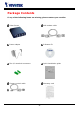
Package Contents If any of the following items are missing, please contact your reseller.
Features and Benefits Video Server is a high-performance networking video multiplexer. With powerful VLIW DSP core and fully optimized algorithm, it can compress and transmit the high quality real-time video through standard TCP/IP inter-network. In addition to meet the basic needs of video feed, many advanced features are added to help building applications of surveillance or web attraction. The state-of-art design well compromises among stable, robust, simple-to-use and flexibility.
reliable to fit into your environment. With this built-in facility, you can easily setup a security system in your home or office. ☆ Weekly schedule for automatic surveillance The user-defined time period will repeat weekly to check any security settings and accordingly sending notification or drive external devices. It is easy to install in SOHO, retail shop and home as a security system.
Physical Description Front Panel Status LED’s Each time Video Server starts up, it will perform power-on-self-test, abbreviated as POST, to examine every hardware module. As soon as the administrator plugs in the power connector both LED’s under the power LED will flash one by one until the diagnosis is done. If the result is good, both status LED’s will turn off for a while and then follows the pattern below.
BNC video inputs “IN” & outputs “OUT” Video Server allows up to four cameras attached at the same time. To ensure video modulation type being detected correctly, cameras should be attached sequentially from “VIDEO1” to “VIDEO4” and powered on before Video Server is powered on. There are also four loop-through connectors of video outputs for conjunction with other capturing devices like time-lapsed VCR. In such case, read the next paragraph for correct settings.
Rear Panel Ethernet 10/100 socket Connect to an Ethernet network with a UTP category 5 cable of length shorter than 100 meters according to the standard. Once the Ethernet cable is connected without error, Video Server will utilize the Ethernet interface prior to the modem attached to COM2.
No. Pin description Regulation 1 DC power output(-) Max. 500mA at 12V DC 2 DC power output(+) Max. 500mA at 12V DC 3 Relay output 2 – Normal Close Max. 1A, 24V DC or 0.5A, 125V AC 4 Relay output 2 – Common Short with NC at initial state 5 Relay output 2 – Normal Open Max. 1A, 24V DC or 0.5A, 125V AC 6 Relay output 1 – Normal Close Max. 1A, 24V DC or 0.5A, 125V AC 7 Relay output 1 – Common Short with NC at initial state 8 Relay output 1 – Normal Open Max. 1A, 24V DC or 0.
device is too far to allow accurate function, an external power source may be used to amplify the RS485 signal. Digital I/O control Video Server provides four pairs of digital inputs and two sets of relay switches. Pin 13 to pin 20 can be connected to external sensors and the state of voltage will be monitored according to the programmed conditions on the configuration page or the external script file. Both relay switches can be used to turn on or off external devices.
Installation To easily fit into various environments, the Video Server automatically detects the attached interfaces and configures itself to the best condition. Therefore users need not care whether the connected cameras are either NTSC or PAL, how to select the network between Ethernet and modem, and whether the Ethernet speed is 10Mbps or 100 Mbps. If the connected motorized camera is on the support list, users only need to plug and play without complicated configurations.
Ethernet Environment Hardware installation Before installing multiple Video Server’s at the well-chosen locations, the administrator should memorize the serial numbers on the packages respectively for future use. Cable connection Shut down all the peripheral devices prior to connection. The video BNC, Ethernet cable and power adapter are essential for basic viewing function.
Initial Access to the Video Server The Video Server can be connected either before or immediately after software installation onto the Local Area Network. The Administrator should complete the network settings on the configuration page. For complete protection from illegal usage, the Video Server provides two privileges and always needs user name and password before access. The standard level is the USER mode that consists of twenty user profiles.
Modem Environment Hardware installation Though Video Server is designed to serve real-time images in Ethernet, it also supports the dial-up network. To use a dial-up network, the Ethernet socket should be left disconnected since Ethernet is the first priority among available interfaces. After powering up, Video Server will detect if any external modem is connected to COM2. As soon as a modem is detected, the heartbeat LED will flash periodically.
Shut down the peripheral devices prior to connection and keep the power adaptor unplugged until other cables are firmly connected. In the environment without Ethernet, administrators can use the included null modem cable to connect to Video Server directly and access point-to-point. After necessary information is entered and saved, turn off Video Server and remove the null modem cable. Follow the installation of modem mode in next paragraph to connect to Internet.
Software installation Via Ethernet Enter the COM2 configuration Web page and select the driver type as modem. Well configure each field for dialing information. Refer to the COM2 section in Definition of Configuration for detailed description. Via null modem Install a new modem 1. Open the control panel and double click the modems icon. 2. Check "Don't detect my modem......" item and click on to install a new modem. 3. From (Standard Modem Type) choose the Standard 33600 bps Modem and click on .
4. Choose the serial port that the included null modem cable is attached to and click on . The null modem is now ready for use. If no Dial-Up adapter exists in the system, Windows may automatically install. prompt Press to to continue. If it does not start automatically, double click the network icon in control panel to install Microsoft dial-up adapter.
Setup a new connection 1. After the 33600 bps modem is installed, open the dialup network folder in Windows to build a new connection. 2. Select the device as the newly installed standard 33600 bps modem and click on . 3. Just enter arbitrary digits as phone number and click on . The phone number here is not important. 4. After connection clicking will on display , in the this new Dial-up Networking folder and will be used for null modem connections.
5. Right-click on the newly setup connection icon for entering properties. 6. In the first General page, clear "Use area code and Dialing Properties" option and click on 7. Select 115200 as the speed and click on . . 8. On the second page, only check "Enable software compression" and "TCP/IP" while leaving others blank. Keep other settings as default values and click on .
Now the connection is ready to use for null modem. Double click the newly setup connection. A dialing information window will pop up. Enter “root” as user name and the serial number labeled on the bottom side of the box as the password and click on . Notice that the letters in the serial number should be capital form. For example, type 'A' instead of 'a'. After some negotiation prompts, a connection status window will show the speed is 115200 bps.
First access to Video Server in null modem mode Through direct connection by null modem cable, administrators can connect to “http://200.1.1.1” in the web browser. “200.1.1.1” will be the default IP address of Video Server in dial-in connection; “200.1.1.100” will be the given IP address for the user's PC by Video Server. The user name and password are the same as what was entered during software installation.
First access to Video Server in modem mode If the dial-out is not prohibited and the attached modem is recognized, Video Server will send out the system startup log and connection log by email or FTP according to user’s settings as soon as the system is ready. That can be used to verify if the settings work. Then Video Server will always wait for someone to dial in. To dial in Video Server, setup a connection in dialup network on PC where the phone number is the phone line of Video Server.
How to Use Open your familiar web browser and connect to Video Server just like a general web site and the video will present on demand. Make sure the web address of the target Video Server is accurate. Authentication After opening the Web browser and typing in the URL of Video Server, a dialogue window will pop out to request a username and password. For administrator’s initial usage of Video Server, enter the username as “root” and the password as the serial number in capital letters.
Installing Plug-in If it is initial access to Video Server via the Web browser supporting server push, the motioned pictures will display directly. If the Web browser is Internet Explorer in Windows, users will be asked to install a new plug-in that is provided by Video Server. This plug-in has been registered for certificate and is used to display motioned pictures in the Internet Explorer. Users may click on to install the plug-in.
Main Page Basic functions are displayed in main entrance page of Video Server. The first figure below is graphic mode that has better visual effect and the second one is text mode that will shorten download time. The main page may look different depending on the PTZ driver or the privilege of the user. Graphic mode Text mode is default if any image button is not available.
Video input selection Switch the video source among up to four cameras connected to Video Server. When clicking on the quad display button, a special quad display of all video inputs is available for simultaneous monitoring. The picture refresh rate of quad display is slower than the single input because it takes time to capture the valid image after changing the video source. The actually appearing buttons depend on the system settings.
can click on click on to short “Common” and “Normal Open” pins of the digital output or to short “Common” and “Normal Close” pins of the digital output. To know more about the digital outputs for external devices, refer to the rear panel introduction of the Chapter Physical Description. Motorized camera control If there is any serial device like motorized camera attached and correctly setup to either COM port, the control panel will appear on permitted users’ main page.
System Configuration Introduction The system configuration can be easily done remotely on Internet Explorer through the Web interface. There are two wizards in addition to classified categories of system configurations. They can give friendly instructions and facilitate the setup job. Alternately administrators may type directly the URL of system configuration, “http:///setup/config.html”, to directly enter the configuration page.
Setup Wizard The setup wizard will guide administrator to enter necessary information including system name, current date and time, administrator’s password, video configuration and captions, and network settings. Administrators can exit the procedures anytime to reserve the current configuration. Finally the setup wizard will ask for reboot to validate the changes and administrators can decide to reboot later.
Definitions of Configuration System parameters Change host name The “host name” is used for the homepage title of main page and displays as the title over the video window on the main page. The maximum string length is 40 characters or 20 characters in double-byte-character-systems like Chinese or Japanese. Adjust date and time There are three ways to adjust system date and time. The easiest is to make Video Server "Sync with computer time".
Security privilege Change root password To change the administrator’s password, type the new password in both text boxes identically. What is typed will be displayed as asterisks for security purposes. The maximum password is 16 characters. After pressing , the web browser will ask administrators for the new password for access. Add new users To add a new user, type the new user's name and password, check respective privilege, and then press to insert the entry.
Network settings Fix the IP address To eliminate incautious mistakes during installation, Video Server will stay in installation mode whenever it starts unless "Reset network at next boot" is disabled. This option can also be disabled using the Installer program. Once the option is disabled, Video Server will skip installation at the next boot and the Installer program will not find the installed units.
“SMTP account name 2” The account login name for the second SMTP server. “SMTP password 2” The password is for the second SMTP account name. “Sender email address” The return email address used in the event the mails fail to be sent out FTP settings “Local FTP server port” This can be other than the default Port 21. The user can change this value from 1 to 65535. After the changed, the external FTP client program must change the server port of connection accordingly.
Any change made to this page will make the system restart to validate. Make sure every field is correctly typed before clicking on . If Video Server fails to response due to erratic settings, perform the restore procedures and run software installation. Administrators should notice that the basic network settings including IP address, subnet mask, default router and DNS servers will be cleared when the network interface is switched to the other between Ethernet and modem.
Maximum frame rate This limits the maximal refresh frame rate. Bandwidth utilization limit Each Video Server can be limited in bandwidth utilization by administrators according to its priority and importance of location. "Bandwidth limit" is most useful to balance network utilization when multiple Video Server’s are installed in the same network. It is more effective than changing image quality only and achieves better performance with adequate image size and quality.
affected by florescent light flashing, shadow shifting, and so on. Set video modulation There are basically two types of video modulation; one is NTSC and the other is PAL. Administrators can select “AUTO” to make Video Server automatically detect the correct type. Select default video source Administrators can choose video channel 1 to 4 or quad screen to be the default video source on the homepage when users connect to Video Server.
COM1 port configuration Choose serial interface There are two types of serial interfaces supported by COM1 but only one interface can be used at one time. Administrators must set the correct “Interface mode” between RS232 and RS485 according to the attached device. Choose device driver If the attached device is PTZ driver, administrators should select the appropriate PTZ model. Refer to our Web site for newly supported PTZ drivers.
COM2 port configuration and modem Choose device driver There are three types of device drivers that can be attached to COM2. The modem is supported by COM2 more than COM1 but only RS232 interface is supported. Administrators should select the device driver and click on save, then the related configuration will show in the lower half of the page. If the modem is selected, ISP information is necessary.
is mailed or uploaded when dial-up connection is successful. Setting the value to zero will make Video Server always keep the connection. Based on the settings of DI/DO in the application, the system will send mails or upload via FTP with image attachment upon the event occurring. In that case Video Server will need a network connection and automatically dial out to the pre-configured server outside.
Application constitution Administrators can use combinations of options on the application page to perform many useful security applications. Video Server provides two application modes; one is performed according to the settings on the web page, the other is performed according to the external command script. Though most settings will automatically be done by the Application Wizard, administrators still can adjust the settings from this page.
“Delay second(s) after event” option to drive some device attached to the digital outputs several seconds after the event happens. If administrators want to receive some snapshots to check the event, select the snapshot channels and check “Send snapshot while trigger condition(s) match”. Video Server will take three snapshots of pre-event, the moment of event, and post-event for selected video channels.
Demonstration account To setup Video Server for demonstration to the public, administrators need to choose the service(s) to be permitted. After checking “Enable demo account”, users may use “demo” as general user name and password is not required. To separate the demo account from primary users can prevent from interfering with the normal operations. Homepage layout There are two homepage display modes.
View log file There is some useful information in the system log including current system configuration and activity history with timestamp for tracking. View parameters The whole system parameters will be categorized listed for administrators to check. The content is the same as CONFIG.INI. Factory default It is used to restore the factory default settings. This means any changes made before will be lost and the system will be reset to the initial status as shipping out of the factory.
Advanced Functions Capture Up-to-date Still Images Get snapshot via URL Administrator and users can use the specific URL to capture the current still image. Video channel URL Video 1 http:///cgi-bin/video1.jpg[?=] Video 2 http:///cgi-bin/video2.jpg[?=] Video 3 http:///cgi-bin/video3.jpg[?=] Video 4 http:///cgi-bin/video4.
Get Continuous Images Select video source and quality and size /cgi-bin/video.jpg[?=] param value Description cam 1 Video 1 2 Video 2 3 Video 3 4 Video 4 1 Medium 2 Standard 3 Good 4 Detailed 5 Excellent 1 Half 2 Standard 3 Double 4 Half x 2 5 Standard x 2 quality size Display all video /cgi-bin/quad.
Video Embedded in Customers’ Homepage In additional to the URL, some scripts should be added to download a plug-in for motion pictures. The following example simply displays title text and a real-time video window in Internet Explorer or Netscape. The user name and password should be configured in advance. Those who are familiar with HTML can easily add more components or rewrite a more vivid and useful homepage.
Download Event-triggered Snapshots There are twelve video image files for four video channels of three stages: pre-alarm, the moment when triggered and post-alarm. Only the snapshots captured by the last event are preserved. Administrator and users can use FTP or URL to get the saved snapshots. They can also be browsed from the application page in system configuration. Get triggered snapshots via URL /cgi-bin/snapshot.
Uploading Snapshots Periodically Upload snapshots to external FTP server In sequential mode, Video Server will send out snapshots according to interval and period settings. If snapshot files are intended for quick updates, it is better to skip date and time suffix. The file name will then be video1.jpg, video2.jpg, video3.jpg and video4.jpg for four channels. If the snapshots are used for occasional monitoring, suffix with date and time can help administrators classify them easily.
Customize Graphics in Homepage While in text mode, there is a small icon named BTN_TEXT.GIF preceding with each link that can be changed by administrators. While in image mode, the default method will use the image stored in Flash memory. The followings are the referenced file name and size limitation of each stored images. Administrators may customize preferred image under the size limit and put to the specific name via FTP. Administrators can download the original images before upload for backup.
Command Script for Complex Applications Besides the application wizard, Video Server provides a more professional command script for advanced applications. The command script will be executed exclusively with the settings in Application page of system configuration except for the weekly schedule. To build the advanced application, follow the steps below. 1. Use any text editor to edit the appropriate command script according to the command format. The script size cannot exceed 500 bytes. 2.
“Digital input state”: H (high), L (low), / (low to high), \ (high to low) “M”: motion detection event.
Practical examples Command line Description MAB=1C; When any motion is detected on channel 1 or 2, “Normal Close” of relay output 1 will short with “Common”. 1H*2\=(5)1O; When DI1 high companied with DI2 transient from high to low, “Normal Open” of relay output 1 will short with COMMON in 5 seconds. B\+C\+D\=W{192. If there is no signal on channel 2 or 3 or 4, a message “no 168.0.1:6000}{no signal!” will be sent to port 6000 of 192.168.0.1 once.
URL for External Device Control Query status of digital inputs /cgi-bin/getdi.cgi Video Server will return status of four digital inputs in one line. Drive digital outputs /cgi-bin/setdo.cgi?do= : 1, 2 for DO1 and DO2 : C, O denoting Normal Close or Normal Open respectively. Move motorized camera in PTZ direction /cgi-bin/control.
Transparent Remote Serial Driver Video Server provides a highly customized control support to third-party serial interface devices aside from PTZ cameras. That means in addition to setting up a custom camera with PTZ commands, users may utilize this mode and introduce a customized homepage to transmit arbitrary user-defined commands from user-side to Video Server. The third-party device connected to the serial port of Video Server will receive the same command sent by the originator.
URL of System Maintenance Download System Log via FTP Besides viewing the system log from the web page, administrators can download the system log file, SYSTEM.LOG, via FTP. To log into the FTP daemon, enter “root” as the user name and the same administrator’s password used in Web access. Restart System via URL /cgi-bin/reset.cgi Restart Video Server without warning. Restore Factory Default Settings via URL /cgi-bin/restore.
Configure System via FTP Administrators can use FTP to configure Video Server much quicker than Web page especially for multiple targets. To configure system via FTP, first download the parameter file, CONFIG.INI, to customize each field according to the environment and then upload back to validate the new settings. To log into the FTP daemon, enter “root” as the user name and the same password used when connecting to the Web server. The serial number of Video Server is the password for the initial access.
(7) (8) (9) (10) (11) (12) (13) (14) (15) (16) (17) (18) (19) (20) (0)0002D1040011 (1) (2) (3) (4) (5) (6) (7) (8) (9) (10) (11) (12) (13) (14) (15) (16) (17) (18) (19) (20) NO 0 en 0 0 [LAYOUT] 1 1 0 1 1 string of maximum 16 characters the followings are as same as the above or YES to enable snapshot mode seconds of s
http:// http:// http://
21 or 1024 ~ 65535 string of maximum 16 characters string of maximum 16 characters string of maximum 40 characters NO or YES 21 or 1024 ~ 65535 NO 80 0 [VIDEO] 1 AUTO NTSC
(0)YES (1)YES (2)YES (3)YES
(4) HOME UP DOWN LEFT RIGHT TELESCOPE WIDE NEAR FAR [SERIAL2] 8 1 0 0 0 RS232 (0) (1) (2) (3) (4) HOME UP DOWN LEFT RIGHT TELESCOPE WIDE NEAR FAR string of maximum 80 characters string of maximum 80 characters string of maximum 80 characters string of maximum 80 characters string of maximum 80 characters string of maximum 80 characters string of maximum 80 characters st
string of maximum 80 characters [ALERT]