VisualServer VS3102 User's Manual
Before You Use Surveillance devices may be prohibited by law in your country. Though VisualServer is not only a high performance surveillance system but also a networked video server, ensure that the operation of such devices are legal before installing this unit for surveillance. It is important to carefully check the contents with the "Package Contents" section after opening the package.
Table of Contents Before You Use........................................................................................ 1 Package Contents ................................................................................... 6 Physical Description............................................................................... 8 Front Panel ........................................................................................................... 8 BNC video input...............................................
Hardware installation ......................................................................................... 24 Cable connection ........................................................................................................................ 25 Power on..................................................................................................................................... 25 Software configuration.......................................................................................
FTP Uploading snapshots periodically to an external FTP server ..................................................... 76 Customizing homepage images .................................................................................................. 76 Viewing system log .................................................................................................................... 77 Uploading the configuration file...........................................................................................
Security configuration URL ....................................................................................................... 85 Network configuration URL....................................................................................................... 85 Video configuration URL ........................................................................................................... 86 Image quality configuration URL................................................................................
Package Contents VisualServer VS3102 Power adapter Camera control cable Null modem cable 6 www.vivotek.
I/O terminal block connector Wrench Installation and document CD Quick installation guide Warranty card 7 www.vivotek.
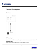
Physical Description Front Panel BNC video input 75Ohms resistance video port for connecting an external camera. To ensure video modulation type being correctly detected, cameras should be attached and powered on before the VisualServer is powered on. RCA audio input The audio input is connected by RCA connector of mono-audio Line-In signal. 8 www.vivotek.
Rear Panel Ethernet 10/100 socket Connect to Ethernet network with a UTP category 5 cable that cannot exceed 100 meters. Once the Ethernet cable is connected without error, VisualServer will utilize Ethernet interface regardless of modem connection. COM port This RS232 serial port can connect with a modem or included null modem cable to utilize dial-up network when Ethernet is not available.
General I/O terminal block 1 Å DI+ INPUT 2 Å DI- INPUT 3 Å SW_COMMON OUTPUT (short with NC at initial state) 4 Å SW_NOPEN (Max. 1A, 24VDC or 0.5A, 125VAC) 5 Å RS485 B (inverting) 6 Å RS485 A (non-inverting) (Max. 50mA, 12VDC) OUTPUT VisualServer provides a very flexible general I/O interface to combine with the user’s security devices such as sensors, alarms, lighting or door locks. The general I/O terminal block has six pins for device control.
Status LEDs Each time VisualServer starts, it will perform a Power-On Self Test, abbreviated as POST hereafter, to examine every hardware module. As soon as the administrator plugs in the power adapter, both LEDs under the network LED will flash one by one until the POST is done. If any module fails, both LEDs will indicate to the users the error according to the pattern listed in Appendix A. If the result is good, both LEDs will turn off for a while and then follows the pattern below.
Restore button There is a button hidden in the box for restoring the system factory default settings. When the system fails to install or operates abnormally, use the included assistant stick in the package and follow the following procedures to reset the system back to its original status. Poke the assistant stick into the hole to press down on the restore button. Restart the system by unplugging and re-plugging the power jack.
How to Install To easily fit into various environments, VisualServer automatically detects the attached interfaces and configures itself to the best condition. Therefore users need not care whether the connected cameras are either NTSC or PAL, how to select the network between Ethernet and modem, and whether the Ethernet speed is 10Mbps or 100 Mbps. If the connected motorized camera is on the support list, users only need to plug and play without complicated configurations.
Ethernet Environment Hardware installation Before installing multiple VisualServers at the well-chosen locations, the administrator should memorize the serial numbers on the packages respectively for future use. Cable connection Shut down all the peripheral devices prior to connection. Connect the supplied cables from VisualServer to related devices according to the following steps. Note that the power adaptor must be kept unplugged until other cables are firmly connected. 14 www.vivotek.
Power on Make sure all cables are correctly and firmly connected before turning on VisualServer. Turn on cameras, sensors, alarm devices, and then attach the power adaptor of VisualServer to the electric power socket*. After the POST (power-on self test) is complete and the result is successful, VisualServer is ready for software configuration as described in this manual. At this stage, network speed and video modulation type are automatically detected.
Software configuration Easy way with installer program In order to configure VisualServers remotely, administrators should keep the serial numbers of the new VisualServers for identification and initial passwords. After successfully mounting VisualServers in the proper position, run the Installer program on the appropriate PC to locate the newly installed VisualServers. VisualServers also support manual setup procedures to non-Windows based environments. The manual procedure is described next.
The IP address shown in "Current IP Address" field is for the administrator's reference. If the administrator wants to use another IP address, modify the IP text field below the list window. If the administrator wants to fix the IP address of the unit, check the option "Use this IP whenever system boots" to skip future installation procedures. Otherwise the unit will need installation whenever it is restarted. 17 www.vivotek.
When IP and options are O.K., click on . A message window will pop open to inform if the IP address is valid. If the IP is not taken by another network device in the network, the Installer program will continue with the setup. Otherwise another message window will warn that the assigned IP conflicts. In this case, administrators should ask the network supervisor for a vacant IP address. 18 www.vivotek.
After successful notification, administrators may keep the address information for user’s request. After clicking on on , the "Assigned" field will be labeled "Yes". Administrators may click directly to access the newly installed server in the default browser. 19 www.vivotek.
While checking “Use this IP whenever system boots”, a dialog window may pop out to ask for “Server FTP Port” and “Root Password” because they are already changed to other than default settings. If the settings are lost, restore default settings and use installer to install again. Once installation is complete, administrators should follow the actions in the "First access to VisualServer" section for necessary checks and configurations. Experienced administrators may use the customized config.
Manual way with existing programs In addition to the provided installer program, some common network tools including ARP and PING can be used to install VisualServer. Open a DOS command prompt window to perform the manual installation. First, type arp –s “assigned IP address” “Ethernet address” to add an entity in the system’s name table.
First access to VisualServer When connecting to VisualServer for the first time, administrators should check security and network settings on the configuration page. For complete protection from illegal usage, VisualServer provides two privileges and always needs user name and password before access. The standard level is the USER mode that consists of twenty user profiles. Each user is able to access VisualServer except for system configuration.
the previous settings. If the install option stays checked, VisualServer will perform the installation procedure every time the system boots up. Details about configurations are described in the "How to Use" section. Related figures are attached for easy reference. 23 www.vivotek.
Modem Environment Hardware installation Before installing VisualServer, the administrator should memorize the serial numbers on the packages respectively for the initial passwords. To use a dial-up network, the Ethernet socket should be left disconnected since Ethernet is the first priority among available interfaces. After powering up, VisualServer will detect if any external modem is connected to the modem port. Once a modem is detected, the heartbeat LED will flash periodically.
Cable connection Shut down the peripheral devices prior to connection. Connect the supplied cables from VisualServer to the related devices according to following steps. Note that power adaptor must be kept unplugged until other cables are firmly connected. For the first access to VisualServer without Ethernet, administrators may use the included null modem cable to connect to COM for direct connection.
Software configuration For the first time, users should connect the included null modem cable between the COM port of VisualServer and any COM port of the PC for initial setup. Install a new modem Open the control panel and double click the modems icon. 26 www.vivotek.
Check "Don't detect my modem......" item and click on to install a new modem. From (Standard Modem Type) choose the Standard 33600 bps Modem and click on . 27 www.vivotek.
Choose the serial port that the included null modem cable is attached to and click on . The null modem is now ready for use. If no Dial-Up adapter exists in the system, Windows will automatically prompt to install. Press to continue. 28 www.vivotek.
Setup a new connection After the 33600 bps modem is installed, open the dialup network folder in Windows to build a new connection. Select the device as the newly installed standard 33600 bps modem and click on . 29 www.vivotek.
Just enter arbitrary digits as phone number and click on . The phone number used here is not important. , this new connection will display in the Dial-up Networking folder and will After clicking on be used for null modem connections. 30 www.vivotek.
Right-click on the newly setup connection icon for properties. In the first General page, clear "Use area code and Dialing Properties" option and click on . 31 www.vivotek.
Select 115200 as the speed and click on . On the second page, only check "Enable software compression" and "TCP/IP" while leaving others blank. . Now the connection is ready for null modem Keep other settings as default values and click on connection. 32 www.vivotek.
Double click the newly setup connection. A dialing information window will pop up. Enter “root” as user name and the serial number labeled on the bottom side of the box as the password and click on . The user name and password are identical to what is used in web access and may be changed by administrators after successful installation. Notice that the letters in the serial number should be capital form. For example, type 'A' instead of 'a'.
First access to VisualServer Through direct connection by null modem cable administrators can open the default web browser and type in 200.1.1.1 as the address and press enter. Note that 200.1.1.1 will be the default IP address in a dial-in connection and 200.1.1.100 will be the given IP address for the user's PC by VisualServer. The user name and password are the same as what was entered during installation. After successful authentication, administrators should see the motion pictures in the main page.
basic configurations. If people other than the administrator will be allowed to use VisualServer, the administrator should add these user profiles in the Security option. When VisualServer accepts dial-in connection and acts as a server, the user name and password used in dialing are the same as what was stored in the user database managed for web access. Any managed user can be authorized during PPP negotiation and access web pages. However only administrators can access the configuration page.
How to Use VisualServer is a well-designed stand-alone video server. With the built-in web server, authorized users may use web browser Internet Explorer to watch the video and hear the audio captured by VisualServer. The powerful video compression processes up to 30 frames per second and makes the scene in your browser as real-time display. The powerful audio compression processes the real-time audio and makes the synchronization of video and audio correctly.
Authentication After opening the Web browser and typing in the URL of VisualServer, a dialogue window will pop up to request a username and password. For administrator’s initial usage of VisualServer, enter the username as “root” and the password as the serial number in capital letters. The serial number can be found on the labels under the body of VisualServer and the top side of the carton. The primary users will be allowed to enter as soon as the administrator finishes adding user profiles.
If it is initial access to VisualServer in Windows, the web browser will ask to install a new plug-in that is provided by VisualServer. This plug-in has been registered for certificate and is used to display the motioned pictures in the browser. Users may click on to install the plug-in. If the web browser does not allow the user to install, check the Internet security option to lower security levels or contact network supervisors. 38 www.vivotek.
Primary user’s capability Main screen with camera view There is a logo image shown in the upper left corner. It can link to other web sites or resources depending on the settings in configuration. The assigned caption and system date/time will display in the banner above the image window. There might be some windows enclosed by red lines shown in the image as soon as motion is detected in the related windows. Click on the configuration link to the right of the image window to enter the configuration page.
PTZ camera control A PTZ motorized camera is provided by customers and should be correctly installed in advance. The control button under the video allows users to control the motorized camera attached to VisualServer with pan/tilt direction and zoom. To access the location set previously, pull down the Preset Position list to select one and click on . Only the administrator can preset the camera locations. Primary users are only allowed to browse the preset locations.
Client Setting If it is the first access to “Client Setting” page in Windows, the web browser will ask to install a new plug-in that is provided by VisualServer. This plug-in has been registered for certificate and is used to setting the client parameters in the browser. Users may click on to install the plug-in. If the web browser does not allow the user to install, check the Internet security option to lower security levels or contact network supervisors. There are two settings for the client side.
real-time issue is worse than UDP protocol. If your environment is behind the firewall and it opens HTTP port (80) only, you can select HTTP protocol only. In this mode, audio will not be sent and you just can see the video only. If you don’t know which protocol you should choose, select the UDP protocol and the client will try these protocols in this order, UDP → TCP → HTTP. After the client connects to the VisualServer successfully, “Protocol Option” will be set as the working protocol automatically.
System configuration There are two methods provided for configuration. Web interface is quite easy and clear to use and FTP with script file is rapid for mass installation. System configuration can be accessed only by administrators. Administrators may type the URL below the figure to directly enter the configuration page. If administrators also want to set certain options through the URL, read the section on advanced usage for reference. http:///setup/config.
System parameters To change the system name, type in the text box after "Host Name". This name will be displayed at the top of the main page. In the case that only the host name is changed, without adjusting date and time of VisualServer, click on "Keep current date and time". There are three ways to adjust system date and time. The easiest is to make VisualServer "sync with computer time". The second is to set the date and time manually. Notice the format in the related field while typing.
When user sets the illegal range of Date or Time, server will not accept this new setting and restore to the last setting. The legal range of year is between: 2000~2035. 45 www.vivotek.
User group administration To change the administrator’s password, type the new password in both text boxes identically. What is typed will be displayed as asterisks for security purposes. After pressing , the web browser will ask administrators for the new password for access. To add a new user, type the new user's name and password and press to insert the entry. There are a total of twenty user accounts.
Network settings Any change made to this page will make the system restart to validate. Make sure every field is correctly typed before clicking on . To eliminate incautious mistakes during installation, VisualServer will stay in installation mode whenever it starts unless "Reset network at next boot" is disabled. This option can also be disabled using the Installer program.
option is ignored in the PPP connection. Administrators may modify the network settings to fit into existing networks. Some broadband service subnet mask may differ from the default value 255.255.255.0 and service providers may assign some specific network settings. Administrators should change the configuration according to what is given by the service provider. The configuration may include "IP address", "Subnet Mask", "Default Router", "Primary DNS" and "Secondary DNS".
If the VisualServer works in variation or low bandwidth (comparing with video bandwidth) environment, the client side will receive the poor quality of media. For improving this situation, you can check the “Improve audio quality in low bandwidth environment” item. It can make the audio quality better, but the media delay is longer and real-time issue is bad.
modem for software installation. 50 www.vivotek.
Video codec parameters Options on this page will affect the image on the main page seen by users. "Text on Video" will be displayed above the video window with a timestamp. The timestamp is captured from date and time of VisualServer that is maintained by a built-in real-time clock. "Color" setting is independent of the connected camera and B/W option might speed up the encoder a little. "Size" option allows users to adjust the image size taking into consideration bandwidth and visual effect.
VS3102 uses MPEG4 codec compression for best streaming solution. The compressed video data is far less than JPEG in normal cases but it still depends on the level of difference between every two sequential images. There are three dependent parameters provided for adjustment. "Maximum Frame Rate" limits the maximal refresh frame rate that can be combined with the "Video Quality Control" to optimize the bandwidth utilization and video quality.
To adjust image settings for best visual quality, press and a motion picture window will pop up for your reference. There are four fields including "Brightness", "Contrast", "Hue" and "Saturation" for video compensation. . Each field has eleven levels ranged from -5 to +5. The user may press settings or to fine-tune the image. When the image is O.K., press to memorize the image to recall the original settings. If parameters are changed without saving, they will be used until the next system startup.
Motion detection Please note that the option "Enable Motion Detection" on the video page must be enabled to make detection effective. VisualServer allows administrators to define at most three detection windows to cover different areas. To monitor a specific area, click to add a new window. The typed text in "Window Name" will show at the top of the window. Use the mouse to drag the border to the desired size or title bar for location.
The following figure shows the screen when is clicked. The monitoring windows will be marked by red squares. 55 www.vivotek.
PTZ camera configuration Since VisualServer can be used in either Ethernet network or PPP network, the single serial port can be used to control either external COM port devices like a PTZ camera or modem. While in PPP interface, go to Modem page for modem configuration. Options on this page will be ignored. VisualServer supports RS232 and RS485 interfaces to control external serial port devices. Refer to the hardware description to connect an RS485 device.
VisualServer can support any other custom camera by selecting "Custom Camera" type. If the attached device is not a PTZ camera, a specific URL can be utilized as an alternative method. See the advanced section for details. To preset the camera head position, press and another window will pop up with the camera view and control buttons for preview. After moving it to the desired position, enter the preset position name and click on .
VisualServer provides five more custom commands other than general pan, tilt, zoom and preset functions. Administrators can click on and refer to the instruction manual of the attached device to setup frequently used functions. The "Commands" should be entered in ASCII format; VisualServer will translate it into binary code and send it out through the serial port. For instance, a text string of "8101ABCDEF" will be translated into five bytes of hexadecimal 81, 01, AB, CD and EF.
If the attached motorized camera is not on the support driver list, choose the proper UART interface and pull down the driver list to select Custom Camera type and click on for further configuration. Setup the serial "Port Settings" according to the instruction manual of the custom camera. The "Baud Rate (bps)" of the serial port is up to 115200 bps. Then enter the specific command related to PTZ in the respective field. The custom command for "Control Setting" should be edited in ASCII format.
When everything is set, click on to save the commands and click on to close the command setting window. to save the configurations of the custom camera. Double-check the driver settings and then click on Since changing drivers will restart the system, a message window like the following figure will pop up to confirm your actions. The system will restart right after clicking on . 60 www.vivotek.
Modem and dialup settings In PPP interface, a modem option will work instead of camera control. Configurations include modem initialization and outside dial-up server. If the users will setup with external sensors and alarms for property security, dial-out is needed to send some snapshot-attached e-mails when the preset conditions are triggered. In such applications, also remember to choose Network option to enter mail server address and recipient's e-mail address.
minutes" will force VisualServer to drop the connection when there is no activity on the connection for the specific period. The range of this period is from 1 to 240 minutes, with 0 indicating a continuous connection. Administrators may let VisualServer keep the connection for a while to allow connections from outside. The IP address given by the ISP can be taken from the connection log that is mailed or uploaded when dial-up connection is successful.
Application Administrators can use combinations of options on the application page to perform many useful security applications. The sending method is selected at the bottom of the page. Both e-mail and FTP use the network settings on the network page. To use FTP to upload snapshots, a timestamp file name can help administrators identify the event. If "FTP put snapshot with date and time suffix" is disabled, the up-to-date snapshot will overwrite the file.
The other "Event operation" can be used to combine motion detection with devices attached to digital input, to drive devices attached to digital output, or send out snapshots for evidence. It helps users establish an easy security system. Administrators may choose any combination of conditions to form special applications according to their personal needs. VisualServer will continuously monitor the channel and digital input every half second.
Homepage layout settings Administrators may give VisualServer a different presence of homepage. The "logo graph" for the system logo in the upper-left corner can be hidden; or the default image from the system memory can be used; or an external resource can be used by assigning a URL. "background graph" is similar. Default images from system memory are quick to get but limited by memory size. Images from external resources can be larger and more beautiful but will need more time to load.
One-shot fast configuration via FTP For quick setup of VisualServer, the administrator can utilize the default CONFIG.INI that may be downloaded from the FTP daemon of VisualServer. To log into the FTP daemon, enter “root” as the user name and the same password used when connecting to the Web server. The serial number of VisualServer is the password for the initial access. Then administrators only need to modify necessary fields and then upload the file to VisualServer with the file name “CONFIG.INI”.
0002D1000001 Read only string IP2001-1A-VVTK-0101 Read only string 2001/08/14 year/month/date. Read only string 07:00:00 hour/minute/second. Read only string
(0) 0002D1000001 Initial value is as same as serial number (1) String shorter than 15 characters (2) The followings are as same as above (3) (4) (5) (6) (7) (8) (9) (10) (11) (12) (13) (14) (15) (16) (17) (18) (19) (20) [LAYOUT] 1 color index: 0 for black, 1 for white, 2 for green, 3 for maroon, 4 for olive, 5 for navy, 6 for purple, 0 7 for gray, 8 for yellow, 9 for lime, 10 for aqua, 11 for fuchsia, 12 for silver, 13 for red, 14 for blue, 15 for t
1 0 for blank, 1 for default image or 2 for loading from URL 1 0 for blank, 1 for default image or 2 for loading from URL http:// link to external resource when logo type is 2, no longer than 80 http:// link when background type is 2, no longer than 80 http://www.vivotek.
192.168.0.1 Standard IP format 168.95.1.1 Standard IP format YES or NO ntp-cup.external.hp.
String shorter than 15 characters / String shorter than 40 characters 80 Integer less than 1024 5001 Integer less than 65535 5002 Integer less than 65535 5003 Integer less than 65535 NO or YES [VIDEO] AUTO or MANUAL.
0 among 5 and -5 YES for fix bit rate, NO for fix quality 384k 1200k, 1000k, 768k, 512k, 384k, 256k, 128k, 64k 30 1, 2, 3, 5, 10, 15, 20, 25, 30 (30 for NTSC only)
Canon VCC3, Dynacolor Dome and Pelco Camera RS232 or RS485 (0) String shorter than 80 characters (1) String shorter than 80 characters (2) String shorter than 80 characters (3) String shorter than 80 characters (4) String shorter than 80 characters UP String shorter than 80 characters DOWN String shorter than 80 characters LEFT String shorter than 80 characters RIGHT String shorter than 80 characters HOME String shorter than 80 characters TE
0 for none, 1 for sequential mode, 8 for event mode, 9 for both 0 0 for FTP, 1 for email YES or NO 0 0
Advanced functions Web Viewing system log Click the button on the configuration page to view the system log file. The content of the file reveals useful information about configuration and connection after the system boots up. Viewing system parameters Click the button on the configuration page to quickly view the whole system parameter set. The content is the same as CONFIG.INI. Restore factory default settings Click the button on the configuration page to restore the factory default settings.
FTP VisualServer not only has web service for easy access but also has a built-in FTP service to make system integrators easy to use. According to settings on the application page, VisualServer can sequentially send updated snapshots over a specific period to an external server with choices of overwriting and time suffix. For security staff, VisualServer can directly send snapshots to an external server as evidence according to event settings.
Viewing system log Download SYSTEM.LOG and open it with any text viewer. The content of the file reveals useful information about configuration and connections after the system boots up. It helps administrators to easily find out who and how VisualServer was accessed since all network access to VisualServer is recorded with timestamp. The system log will scroll to keep the newest messages as eliminate old ones.
the “Reset network at next boot” option is enabled or not. After VisualServer boots up, reload the web page in the browser. If power fails during the software upgrade, the program in the memory of VisualServer may be destroyed permanently. If VisualServer cannot restart properly, ask the dealer for technical service. 78 www.vivotek.
Telnet VisualServer has a Telnet daemon for administrators to access some seldom used functions. Using any general terminal program to connect to VisualServer will prompt the user for a password. Username is not requested here since only administrators can access the Telnet daemon. The password is as same as that used for web access. After logging in, type "help" for the command list. If "debug" or "dinote" is not executed, Telnet will disconnect automatically after being idle for 1 minute.
Set digital outputs To set digital output to connect NO with COMMON, type "DO=L". To set digital output to connect NC with COMMON, type "DO=H". Erase snapshots stored in Flash memory Typing "erase image" will clear all snapshots saved in Flash.memory. Erase logo and graphic buttons Typing "erase graph" will clear all images used on the homepage. If no new images are uploaded, the system will switch to text mode and use default images instead.
URL commands of VisualServer For some customers who already have their own web site or web control application, VisualServer can be easily integrated through convenient URLs. This section lists the commands in URL format corresponding to the basic functions of VisualServer. Some RFC standards related to HTML may be a good reference for implementation of the customized homepages. Capture update Snapshot of JPEG image /cgi-bin/video.
Clear data mode serial port driver This URL applies to the attached serial port device including supported PTZ cameras or non-supported custom cameras. Note the serial port settings of custom cameras must be correctly defined in advance. Send command to device attached to COM /cgi-bin/senddata.cgi?data=123456,ABCDEF&flush=yes&wait=1000&read=6 This hyperlink will inform VisualServer to send out binary format commands to the COM with “0x12, 0x34, 0x56” followed by “0xAB, 0xCD, 0xEF”.
Page URL The configuration page has a frame layout including an option list frame and an option page frame. Referenced URLs, except for the configuration page, direct users to the option page frame only. Some pages, like image quality setting and preset setting, are opened in new windows for preview. These URLs can be accessed only by administrators. Homepage name Referenced URL Client setting page /client.html configuration page /setup/config.html system option /setup/system.
System resource URL There are some images used on the homepage when the homepage layout is in image mode. Administrators may use the following links to show the images saved in VisualServer on another page. To change the images referenced by the URL, refer to the homepage layout section in configuration. Resource name Referenced URL system logo image /pic/logo.gif background image /pic/back.gif icon image for link indicator /pic/btn_text.
Security configuration URL URL: /setup/security.cgi NAME VALUE DESCRIPTION rootpass change root password username add new user userpass new user's password deluser existing user name Network configuration URL URL: /setup/network.
ftp1 primary FTP server ftpuser1 user name for primary FTP server ftppass1 password for primary FTP server ftpfolder1 upload folder in primary FTP server ftp2 secondary FTP server ftpuser2 user name for secondary FTP server ftppass2 passw
mode frame enablemd flip mirror 768000 set bit rate to 768K bps 1000000 set bit rate to 1000K bps 1200000 set bit rate to 1200K bps Auto let VisualServer detect video modulation NTSC set directly to NTSC type set directly to PAL type 1 set maximum frame rate to 1 fps 2 set maximum frame rate to 2 fps 3 set maximum frame rate to 3 fps 5 set maximum frame rate to 5 fps 10 set maximum frame rate to 10 fps 15 set maximum frame rate to 15 fps 20 set maximum frame ra
restore recall the original settings save save the parameters Camera configuration URL URL: /setup/camera.cgi NAME VALUE DESCRIPTION interface RS232 switch COM to RS232 switch COM to RS485 auto let VisualServer auto detect camera 1 non-PTZ camera device 2 Sony EVI-D30/31 3 Canon VCC1 4 Canon VCC3 5 DynaDome/SmartDOME 6 Pelco D protocol 7 third party PTZ camera driver Camera preset configuration URL URL: /setup/preset.
str5 button name of custom command 5 of COM com1 custom command 1 of COM com2 custom command 2 of COM com3 custom command 3 of COM com4 custom command 4 of COM com5 custom command 5 of COM Custom camera configuration URL URL: /setup/custom.
method Tone (ATDT) make modem dial in tone Pulse (ATDP) make modem dial in pulse reatt redial attempts discon minutes delay before disconnection init command to initialize modem phone1 phone number of primary ISP user1 user name for primary ISP pass1 password for primary ISP phone2
mdalarm < not required > trigger DO when motion detected ioupload < not required > upload snapshot when DI condition matched mdupload < not required > upload snapshot when motion detected sinter seconds interval for sequential mode sbegin time to start sequential mode send time to stop sequential mode Homepage layout configuration URL URL: /setup/layout.
Appendix A. POST procedure After the power has been turned on, VisualServer will perform a self-diagnostic to locate any possible hardware defects. If the power indicator is dim at the beginning, the power fails to proceed further. While the POST is proceeding, the status LED indicators will keep blinking interchanged until finished or any fatal error happens. If either status LED indicator is dim at the beginning, the LED may be broken.
B. Frequently asked questions Q. What if I forget my password? A. Every access to VisualServer needs authentication. If you are one of the managed users, you have to ask the administrators for the password. If you are the administrators, there is no way to recover the root password. The only way to regain access to VisualServer is to utilize the default setting button on the rear panel to restore the factory settings and reinstall it. Q.
from modem property in the control panel. While in Ethernet, it may be due to time taken in storing snapshots into memory upon events occurring. Q. How does VisualServer detect the supported PTZ cameras automatically? A. If there is no camera detected, VisualServer will monitor the CTS of the camera control cable continuously. As long as the CTS is detected, VisualServer will try to handshake with supported cameras until a supported camera is found.
Q. I have a PTZ camera that is not on the supported list. How can I control it? A. VisualServer provides a custom camera command interface to control the cameras that are not supported. The details are described in the manual. Be sure the COM port settings are applied to the camera specification. The camera control cable included is shown in the package content. Prepare your own cable if necessary. The general PTZ command is composed of one start command and one stop command.
C. Technical specifications Remote Management General I/O Configuration and system log can be accessed via Web browser and FTP application remotely. 1 opto-isolated sensor input (max. 12VDC 50mA) 1 output relay (max. 24VDC 1A, 125VAC 0.
Electromagnetic Compatibility (EMC) USA - This equipment has been tested and found to comply with the limits for a Class B digital device, pursuant to Part 15 of the FCC Rules. These limits are designed to provide reasonable protection against harmful interference in a residential installation. This equipment generates, uses and can radiate radio frequency energy and, if not installed and used in accordance with the instructions, may cause harmful interference to radio communications.