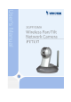
Product name: Wireless Network Camera with Pan/Tilt(PT7137) Release Date: 2005/12/27 Manual Revision: 1.02 Web site: www.vivotek.com Email: technical@vivotek.com sales@vivotek.com Made in Taiwan. ©Copyright 2000-2005. All rights reserved -1www.vivotek.
Before You Use This Product The use of surveillance devices may be prohibited by law in your country. The Network Camera is not only a high-performance web-ready camera but also can be part of a flexible surveillance system. It is the user’s responsibility to ensure that the operation of such devices is legal before installing this unit for its intended use. It is important to first verify that all contents received are complete according to the list in the "Package Contents" chapter.
Table of Contents Before You Use This Product......................................................................2 Package Contents ....................................................................................6 Installation .............................................................................................7 Hardware installation..........................................................................7 Software Installation .................................................................
Video Settings............................................................................ 39 Video orientation ........................................................................ 39 Audio settings ............................................................................ 40 Image Settings .......................................................................... 41 Camera Control ............................................................................... 42 Email & FTP ..........................
Configuration file ........................................................................ 74 Upgrade firmware ....................................................................... 75 D. Technical specifications ................................................................. 76 -5www.vivotek.
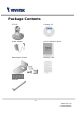
Package Contents PT7137 Software CD Power adapter Quick installation guide Mounting Kit & Pads Warranty card Antenna -6www.vivotek.
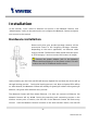
Installation In this manual, "User" refers to whoever has access to the Network Camera, and "Administrator" refers to the person who can configure the Network Camera and grant user access to the camera. Hardware installation Please verify that your product package contains all the accessories listed in the foregoing Package Contents. Depending on the user’s application, an Ethernet cable may be needed. The Ethernet cable should meet the specs of UTP Category 5 and not exceed 100 meters in length.
will become lighted. Operating in either network mode, the green LED will flash every second as heartbeat to indicate alive. If the red LED is blinking, please check the network connections. To install in Ethernet Make sure the Ethernet is firmly connected to a switch hub. After attaching the Ethernet cable plug in the power adapter. If the LED turns out to be steady blue, go to next paragraph “Software installation”. If the Ethernet is not available, Network Camera will switch to wireless LAN mode.
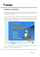
Software Installation In this manual, "User" refers to whoever has access to the Network Camera, and "Administrator" refers to the person who can configure the Network Camera and grant user access to the camera. At the end of the hardware installation, the Administrator must place the product software CD into the CD-ROM drive of the PC running in MS Windows. An auto-run program will pop up (If the program is not on auto-run, go to the root directory of the software CD and click on “autorun.exe”).
Upon Installation Wizard’s start up, a searching box will pop up. This program searches for Vivotek’s product on the same LAN: After searching, Vivotek Video Servers or Network Cameras will be located by the Installation Wizard. There may be several entries shown Administrator in may the window. The differentiate the Network Cameras with the serial number. - 10 - www.vivotek.
For the series number in the “Serial Number” field, please check the label on the bottom of the camera. The IP addresses shown in the "Current IP Address" field reflect those on the local network. They may be from the DHCP server. If there is no DHCP server, the camera will try to find a free IP address (this takes from 15 second to 3 minutes, depending on the LAN status). The method of finding IP address is seeking from 192.168.0.99, to 192.168.0.254.
For more detailed usage of the Installation Wizard, please refer to the user’s manual of the Installation Wizard included in the product CDROM to find the location of the Network Camera. There may be many Network Cameras in the local network. Users can differentiate the Network Cameras with the serial number. The serial number is printed on the labels on the carton and the back of the Network Camera body. Please refer to the user’s manual of Installation Wizard for detail. - 12 - www.vivotek.
Initial Access to the Network Camera Check Network Settings The Network Camera can be connected either before or immediately after software installation onto the Local Area Network. The Administrator should complete the network settings on the configuration page, including the correct subnet mask and IP address of gateway and DNS. Ask your network administrator or Internet service provider for the detail information.
How to Use Authentication After opening the Web browser and typing in the URL of the Network Camera, a dialogue window pops up to request a username and password. Upon successful authentication, the following figure is displayed. The foreground is the login window and the background shows the message if authentication fails. The user may check the option box to save the password for future convenience. This option is not available to the Administrator for obvious reason.
Installing plug-in For the initial access to the Network Camera in Windows, the web browser may prompt for permission to install a new plug-in for the Network Camera. Permission request depends on the Internet security settings of the user’s PC or notebook. If the highest security level is set, the computer may prohibit any installation and execution attempt. This plug-in has been registered for certificate and is used to display the video in the browser. Users may click on to proceed.
Primary user’s capability Main Screen with Camera View The main page layout has three parts: Configuration functions: The camera can be configured using these user interfaces. Camera View: What the camera sees. Pan/Tilt control buttons: These buttons provide a command interface to control the aim of the camera. Click on the configuration link to the left of the image window to enter the configuration page. - 16 - www.vivotek.
The Configuration: “Snapshot” The button provides users a fast way to capture a single image of the video from the Network Camera. “Client Settings” Clicking on this button links you to the client setting pages, please check the following session for more details. “Configuration” Only the Administrator can access camera configurations. The camera view: The information bar at the top of the camera view shows the connection type to the Network Camera and the current date/time.
factor for specified area in the camera view. Users can also move the white frame to select the area of the video that she/he wants to view. “Disable digital zoom” The checkbox selection allows users to disable/enable the digital zoom function. “Zoom Factors” The range of zoom factor is from 100% to 400%, users can select any integer factor inside this area. “Hide” Click on this button can close the digital zoom control window.
“Stop” The option will disconnect to the Network Camera. “Play volume” Click on this button can adjust the audio volume. “Mute” Disable audio at client side. The pan/tilt control buttons: The direction buttons are for Left, Right, Up, Down, and Home functions. The Home button centers the camera. “Go to” Once the Administrator has determined the preset positions; the User can aim the camera using this control. “Pan speed” This button sets the moving range of the “Left” and “Right” commands.
Client settings At the initial access to the “Connection type” page in Windows, the web browser will ask for a new plug-in installation, the plug-in being the Network Camera. This plug-in has been registered for certification and can be used to change the parameters at the client’s site. The user may click on to install the plug-in. If the web browser does not allow the user to complete the installation, check the Internet security to lower the security level or contact your IT or networking supervisor.
The UDP protocol allows for more real-time audio and video streams. However, some packets may be lost due to network burst traffic and images may be obscured. The TCP protocol allows for less packet loss and produces a more accurate video display. The downside with this protocol is that the real-time effect is worse than that with the UDP protocol. If no special need is required, UDP protocol is recommended. Generally speaking, the client’s choice will be in the order of UDP → TCP.
Administrator’s capability Fine-tuning for Best Performance Best performance generally equates to the fastest image refresh rate with the best video quality, and at the lowest network bandwidth as possible. The three factors, “Maximum frame rate”, “Constant bit rate”, and “Fix quality” on the Audio and Video Configuration page, are correlative to allow for achieving the best performance possible. - 22 - www.vivotek.
For Viewing by Mobile Phone Most 3GPP cell phone supports media streaming with MPEG4 video and GSM-AMR audio. Due to the limitation of the bandwidth for 3GPP, only 176x144 size video is supported for cell phone viewing. Select the “Configure for mobile viewing” option will change the range of other related video settings.
Somewhere Between Real-time and Clear Images If you have a broadband network, set “Fix quality” at ”Normal” or better, rather than setting “Fix bit rate”. You can also fix the bandwidth according to your actual network speed and adjust the frame rate. 15 fps. Start from 30 fps down for best results but not below If the image qualities are not improved, select a lower bandwidth setting. - 24 - www.vivotek.
Opening accounts for new users 1 2 3 Protect Network Camera by passwords The Network Camera is shipped without any password by default. That means everyone can access the Network Camera including the configuration as long as the IP address is known. It is necessary to assign a password if the Network Camera is 1 to enable protection. intended to be accessed by others. Type a new word twice in ○ This password is used to identify the administrator. Then add an account with user 2 .
Build a security application The Administrator can use the built-in motion detection to monitor any movement to perform many useful security applications. To upload the snapshots, users can choose either email or FTP according to user’s needs. Both e-mail and FTP use the network settings on the Email and FTP page. Refer to the definition section for detail configuration. 1. Click on “Configuration” on homepage, 2. Click on “Motion detection” at the left column, 3. Check “Enable motion detection”, 4.
Software revision upgrade Customers can obtain the up-to-date software from the web site of Vivotek. An easy-to-use Upgrade Wizard is provided to upgrade the Network Camera with just a few clicks. The upgrade function is opened to the Administrator only. To upgrade the system, follow the procedures below. 1. Download the firmware file named “xxx.pkg” from the appropriate product folder. 2. Run the Upgrade Wizard and proceed following the prompts. Refer to the instructions of the Upgrade Wizard for details.
Definitions in Configuration Only the Administrator can access system configuration. Each category in the left column will be explained in the following pages. The bold texts are the specific phrases on the Option pages. The Administrator may type the URL below the figure to directly enter the frame page of configuration. If the Administrator also wants to set certain options through the URL, read the reference appendix for details. http:///setup/config.
System parameters "Host name" The text displays the title at the top of the main page. “Turn off the LED indicator” Check this option to shut off the LED on the rear. It can prevent the camera’s operation being noticed. "Keep current date and time" Click on this to reserve the current date and time of the Network Camera. An internal real-time clock maintains the date and time even when the power of the system is turned off.
Security settings “Root password” Change the Administrator’s password by typing in the new password identically in both text boxes. The typed entries will be displayed as asterisks for security purposes. After pressing , the web browser will ask the Administrator for the new password for access. “Add user” Type the new user's name and password and press to insert the new entry. The new user will be displayed in the user name list. There is a maximum of twenty user accounts.
Network settings Any changes made on this page will restart the system in order to validate the changes. Make sure every field is entered correctly before clicking on . Network type “LAN” & “PPPoE” The default type is LAN. Select PPPoE if using ADSL "Get IP address automatically" & “Use fixed IP address” The default status is “Get IP address automatically”. This can be tedious having to perform software installation whenever the Network Camera starts.
“Password” The password of PPPoE account “Confirm password” Input password again for confirmation HTTP “Http port” This can be other than the default Port 80. Once the port is changed, the users must be notified the change for the connection to be successful. For instance, when the Administrator changes the HTTP port of the Network Camera whose IP address is 192.168.0.100 from 80 to 8080, the users must type in the web browser “http://192.168.0.100:8080” instead of “http://192.168.0.100”.
http:///setup/network.html is the domain name or original IP address of the Network Camera. - 33 - www.vivotek.
WLAN Configuration “SSID” (Service Set Identifier), it is a name that identifies a wireless network. Access Points and wireless clients attempting to connect to a specific WLAN (Wireless Local Area Network) must use the same SSID. The default setting is default. Note: The maximum length of SSID is 32 single-byte characters and SSID can’t be any of “, <, > and space character.
▶ “Shared” – allows communication only with other devices with identical WEP settings. “Key length” The administrator can select the key length among 64 or 128 bits. 64bits is the default setting. “Key format” Hexadecimal or ASCII. “HEX” is the default setting. ▶ “HEX” digits consist of the numbers 0~9 and the letters A-F. ▶ “ASCII” is a code for representing English letters as numbers from 0-127 except “, <, > and space characters that are reserved.
http:///setup/wireless.html is the domain name or original IP address of the Network Camera. - 36 - www.vivotek.
DDNS “Enable DDNS” This option turns on the DDNS function. “Provider” The provider list contains four hosts that provide DDNS services. Please connect to the service provider’s website to make sure the service charges. “Host Name” If the User wants to use DDNS service, this field must be filled. Please input the hostname that is registered in the DDNS server. “Username/E-mail” The Username or E-mail field is necessary for logging in the DDNS server or notify the User of the new IP address.
Access List The access list is to control the access permission of clients by checking the client IP address. There are two lists for permission control: Allow List and Deny List. Only those clients whose IP address is in the Allow List and not in the Deny List can connect to the Video Server or Network Camera for receiving the audio/video streaming. Both Allow List and Deny List consist of a list of IP ranges.
Audio and Video General “Configure for computer viewing” To make quick setting for computer viewing “Configure for mobile viewing” To make quick setting for cell phone viewing Video Settings “Video title” The text string can be displayed on video “Color” Select either for color or monochrome video display. “Frame Size” There are four options for video sizes. “160x120”, “176x144”, “320x240”, “640x480”.
“Mirror” Horizontally rotate the video. Check options both if the Network Camera is installed upside down. “White balance” Adjust the value for best color temperature. Audio settings “mute” Audio mute “Audio type” Select audio codec “AAC” or “GSM-AMR” and the bit rate http:///setup/audiovideo.html is the domain name or original IP address of the Network Camera. - 40 - www.vivotek.
Image Settings Click on this button to pop up another window to tune “Brightness”, “Contrast”, “Hue” and “Saturation” for video compensation. Each field has eleven levels ranged from -5 to +5. “Brightness” “Contrast” value 0 tuning. and fields the indicates auto The user press fine-tune In may to the image. When the image is O.K., press to set the image settings. Click on this to recall the original settings without incorporating the changes. - 41 - www.vivotek.
Camera Control Camera control area Preset function area On the Camera Control page, there are two main function control areas: Camera control area The pan and tilt functions can be controlled with these buttons. The “Left” button aims the camera to the left; the “Right”, “Up”, and “Down” buttons aim the camera accordingly. The “Home” button aims the camera to the center. “Pan speed” This controls the range of the horizontal movement of the camera.
“Tilt speed” This controls the range of the vertical movement of the camera. The greater the value, the greater angular movement when performing the “Up” or “Down” functions would be. “Auto pan/patrol speed” This defines the speed of panning and patrol, the greater the value, the faster the speed. Preset function area ”Current position”, If the User wants to save the current view as a preset location, enter a name for each of the current video view at “current position” and click on the “Add” button.
Email & FTP Email When the SMTP server support SMTP authentication, users need to give the valid user name and password to send email via the server. “Sender email address”, the email address of the sender. There are two external mail server can be configured, primary and secondary email server, The network camera will use primary server as default , and use secondary server when primary server is unreachable. “Server address” The domain name or IP address of the external email server.
this value from 1025 to 65535. “User name” Granted user name on the external FTP server. “Password” Granted password on the external FTP server. “Remote folder name” Granted folder on the external FTP server. The string must conform to that of the external FTP server. Some FTP servers cannot accept preceding slash symbol before the path without virtual path mapping. Refer to the instructions for the external FTP server for details. The folder privilege must be open for upload.
Motion detection “Enable motion detection” Check this option to turn on motion detection. Click on this button to add a new window. At most three windows can exist simultaneously. Use the mouse to click, hold, and drag the window frame to resize or the title bar to move. Clicking on the ‘x’ at the upper right-hand corner of the window to delete the window. Remember to save in order to validate the changes. Click on this button to save the related window settings.
Application settings Snapshot “Enable snapshot” Enable/Disable snapshot application. Weekly schedule “Sun” ~ “Sat” Select the days of the week to perform the application. Select “Always” or input the time interval. Snapshot file name prefix The prefix name will be added on the file name of the snapshot images. Send out the snapshot while motion detection There are three windows for motion detection each can be assigned a name. Select the windows which need to be monitored.
Sequential operation “Snapshot interval : second(s)” Network Camera will send snapshots at the specified intervals to the external server using the method selected below. Remember: This operation is still subject to the conditions set in the weekly schedule. Method for sending snapshot “Email” This selects the uploading method following the intervals set above. The snapshot named “prefix-yyyymmdd-hhmmss.jpg” will be attached in the email.
- 49 - www.vivotek.
System log The Network camera support log the system messages on remote server. The protocol is compliant to RFC 3164. If you have external Linux server with syslogd service, use “-r” option to turn on the facility for receiving log from remote machine. Or you can use some software on Windows which is compliant to RFC 3164. Check “Enable remote log” and input the “IP address” and “port” number of the log server to enable the remote log facility. In the “Current log”, it displays the current system log file.
Viewing system parameters Click on this link on the configuration page to view the entire system’s parameter set. The content is the same as those in CONFIG.INI. - 51 - www.vivotek.
Maintenance Four actions can be selected “reboot” click the reboot button to restart system “factory default” Click on Factory default button on the configuration page to restore the factory default settings. Any changes made so far will be lost and the system will be reset to the initial factory settings. The system will restart and require the installer program to set up the network again.
Appendix A. Troubleshooting Status LED The following table lists the LED patterns in general. Condition LED color Loading system after power on Steady red During booting procedure Steady green, blue and red Detecting and setting network Steady green and blue. Blink red till IP address is confirmed After network is setup (system up) Blink green every second and steady red During the upgrade firmware process Blink green every second and fast blink red Enable audio Steady blue.
Restoring the factory defaults will erase any previous settings. B. URL commands of the Network Camera For some customers who already have their own web site or web control application, the Network Camera can be easily integrated through convenient URLs. This section lists the commands in URL format corresponding to the basic functions of the Network Camera. Get server parameter values Note: This request require administrator access Method: GET/POST Syntax: http:///cgi-bin/admin/getparam.
where is =\r\n [] is the actual length of content. Example: request IP address and it’s response Request: http://192.168.0.123/cgi-bin/admin/getparam.cgi?network_ipaddress Response: HTTP/1.0 200 OK\r\n Content-Type: text/html\r\n Context-Length: 33\r\n \r\n network.ipaddress=192.168.0.123\r\n Set server parameter values Note: This request require administrator access Method: GET/POST Syntax: http:///cgi-bin/admin/setparam.
parameter is assigned. The can be a full URL path or relative path according the the current path. If you omit this parameter, it will redirect to an empty page. (note: The return page can be a general HTML file(.htm, .html) or a Vivotek server script executable (.vspx) file. It can not be a CGI command. It can not have any extra parameters. This parameter must be put at end of parameter list) Return: HTTP/1.
\r\n network.ipaddress=192.168.0.123\r\n Available parameters on the server NOTE: The bold characters in table are the default value of each parameter. Group: System NAME VALUE DESCRIPTION hostname <Network Camera > ledoff 0 Do not turn off the led indicator (r/w) 1 Turn off the led indicator date year, month and date separated by slash.
restore 0 Restore the system parameters to default (w) value. Positive integer Restore the system parameters to default value and restart the server after seconds. reset 0 ~ 65535 Restart the server after seconds. -1 Not restart the server. viewmode 0 Using the profile of viewing by computer (r/w) 1 Using the profile of viewing by mobile phone (w) Group: Security NAME VALUE DESCRIPTION username_<1~20
pppoepass resetip 1 enable to get ipaddress, subnet, router, dns1, (r/w)(restart) dns2 from DHCP server at next reboot 0 Using preset ipaddress, subnet, router, dns1, dns2 ipaddress IP address of server (r/w) (restart) subnet <192.168.0.99> subnet mask (r/w) (restart) router <255.255.255.
(r/w) 15 characters> returnemail localftpport ftp1 number name less FTP port <21> or IP primary FTP server than 40 characters > ftpport1 ftpuser1 ftppass1
rtspport <554> videoport audioport accessname <5558> number less audio Channel port for RTP <5556>
keyselect 1~4 Default key number (r/w) <1> key1 (depends <0000000000> on keyformat & keylength) key2 (depends <0000000000> on keyformat & keylength) key3 (depends <0000000000> on keyformat & keylength) key4
Group: Video NAME VALUE DESCRIPTION text codectype 0 MPEG4 (r/w) 1 MJPEG keyinterval 1, 3, 5, 10, 30, 60, 90, Key frame interval (r/w) 120 <60> size 1 half (r) 2 half x 2 3 normal 4 normal x 2 5 double 256 This field is obsolete (use resolution) string shorter enclosed caption resolution 176x144 (for mobile) Video resolution 176 x 144 (r/w) 160x120 Video resolution 160 x 120 320x240 Video resolution 320 x 240 640x480 (for Vid
50000 set bit rate to 50K bps 64000 set bit rate to 64K bps 128000 set bit rate to 128K bps 256000 set bit rate to 256K bps 512000 set bit rate to 512K bps 768000 set bit rate to 768K bps 1000000 set bit rate to 1000K bps 1500000 set bit rate to 1500K bps 2000000 set bit rate to 2000K bps 3000000 set bit rate to 3000K bps 4000000 set bit rate to 4000K bps maxframe 1 set maximum frame rate to 1 fps (r/w) 2 set maximum frame rate to 2 fps 3 set maximum frame rate to 3 fps 5 set
p 0 Do not overlay time stamp on video (r/w) Group: Audio NAME VALUE DESCRIPTION type AAC4 (for computer) set codec to AAC (r/w) GAMR (for mobile) set codec to GSM-AMR aacbitrate 16000 set AAC bitrate to 16K bps (r/w) 32000 set AAC bitrate to 32K bps amrbitrate 4750 set AMR bitrate to 4.75K bps (r/w) 5150 set AMR bitrate to 5.15K bps 5900 set AMR bitrate to 5.9K bps 6700 set AMR bitrate to 6.7K bps 7400 set AMR bitrate to 7.4K bps 7950 set AMR bitrate to 7.
(r/w) tiltspeed -5 ~ 5 Tilt speed -5 ~ 5 Zoom speed -5 ~ 5 Auto pan speed 0 ~ 9999 Time to dwelling when patrol (r/w) zoomspeed (r/w) autospeed (r/w) dwelling (r/w) presetname_<0~9> Text string shorter than The name of preset location (r/w) 40 characters. presetpan_<0~9> -1024 ~ 1024 The pan coordinate of preset location. -56 ~ 144 The tilt coordinate of preset location. (r/w) presettilt_<0~9> (r/w) patrolname_<0~19> Text string shorter than The name of patrol location (r/w) 40 characters.
winheight_<0~2> 0 ~ 240 Height of motion detection window. (r/w) <0> winobjsize_<0~2> 0 ~ 100 Percent of motion detection window (r/w) <0> winsensitivity_<0~2 0 ~ 100 Sensitivity of motion detection window > <0> (r/w) update 1 Update the above motion detection settings (w) to take effect Group: DDNS NAME VALUE DESCRIPTION enable 0, 1 Enable or disable the dynamic dns. (r/w) provider <0> 1~6 dyndns.org (dynamic) (r/w) dyndns.org (custom) tzo.com dhs.org safe100.net dyn-interfree.
NAME VALUE DESCRIPTION enable 0, 1 Enable or disable the UPNP presentation (r/w) service. <1> Group: UPNPfor NAME VALUE DESCRIPTION enable 0, 1 Enable or disable the UPNP port forwarding (r/w) service. <0> Group: App NAME VALUE DESCRIPTION scriptname
Syntax: http:///cgi-bin/camctrl.
Syntax: http:///cgi-bin/recall.cgi? recall=[&return=] parameter value recall Text description string less One of the present positions to recall. than 30 characters return Redirect to the page after the parameter is assigned. The can be a full URL path or relative path according to the current path. If you omit this parameter, it will redirect to an empty page.
Content-Length: \r\n \r\n If(method == get || method == set) { tue=\r\n wed=\r\n … } Else if(method == normal) { Application page contents } parameter Value snapshot_enable 0 description Enable snapshot application 1 Disable snapshot application weekday 0,1,2,3,4,5,6 The array indicate weekly schedule time_method always 24 hours full day interval Select begin time and end time begin_time hh:mm Begin time of weekly schedule end_time hh:mm En
send_method ftp_suffix mail Send snapshot by mail ftp Send snapshot by ftp 0/1 Enable/Disable file name prefix Capture single snapshot Note: This request require normal user privilege Method: GET/POST Syntax: http:///cgi-bin/video.jpg Server will return the most up-to-date snapshot in JPEG format. The size and quality of image will be set according to the video settings on the server. Return: HTTP/1.
[&privilege=][…][&return=] parameter value Description method add Add an account to server. When using this method, “username” field is necessary. It will use default value of other fields if not specified. delete Remove an account from server. When using this method, “username” field is necessary, and others are ignored. edit Modify the account password and privilege. When using this method, “username” field is necessary, and other fields are optional.
Syntax: http:///cgi-bin/admin/syslog.cgi Server will return the up-to-date system log. Return: HTTP/1.0 200 OK\r\n Content-Type: text/plain\r\n Content-Length: \r\n \r\n \r\n Configuration file Note: This request requires administrator privilege Method: GET/POST Syntax: http:///cgi-bin/admin/configfile.cgi Server will return the up-to-date configuration file. Return: HTTP/1.
Upgrade firmware Note: This request requires administrator privilege Method: POST Syntax: http:///cgi-bin/admin/upgrade.cgi Post data: fimage=[&return=]\r\n \r\n Server will accept the upload file named to be upgraded the firmware and return with if indicated. - 75 - www.vivotek.
D. Technical specifications - System - Audio CPU: Vivotek VVTK-1000 RAM: 32MB SDRAM ROM: 4MB FLASH ROM AAC, GSM-AMR - Microphone - Networking Protocol TCP/IP, HTTP, SMTP, FTP, DDNS, UPnP, Telnet, NTP, DNS, DHCP and RTSP Physical 10 baseT or 100 baseT Fast Ethernet auto negotiation WLAN 802.
Technology License Notice AMR Technology This product includes AMR narrowband speech coding technology licensed by VoiceAge. Please refer to http://www.voiceage.com/ for more details. MPEG-4 AAC Technology This product includes MPEG-4 AAC audio coding technology licensed by Via Licensing. Please refer to http://www.vialicensing.com/ for more details. MPEG-4 Visual Technology This product includes one MPEG-4 encoder and one MPEG-4 decoder license. Installation of more than one decoder is prohibited.
Electromagnetic Compatibility (EMC) This device compiles with FCC Rules Part 15. Operation is subject to the following two conditions. • • This device may not cause harmful interference, and This device must accept any interference received, including interference that may cause undesired operation. USA - This equipment has been tested and found to comply with the limits for a Class B digital device, pursuant to Part 15 of the FCC Rules.