Managed Storage Switch real world solutions for storage networking 1·888·AT·VIXEL / www.vixel.com Vixel HQ / 11911 North Creek Parkway South / Bothell, WA 98011 / USA tel 425 806 5509 / fax 425 806 4050 Vixel Europe / P.O.
Copyright © 2003 Vixel Corporation. All rights reserved worldwide. No part of this document may be reproduced by any means nor translated to any electronic medium without the written consent of Vixel Corporation. Information furnished by Vixel Corporation is believed to be accurate and reliable. However, no responsibility is assumed by Vixel Corporation for its use; or for any infringements of patents of other rights of third parties which may result from its use.
Table of Contents 1 Introduction................................................................... 1 2 Installation..................................................................... 3 3 Management ................................................................ 11 4 Technical Reference...................................................... 54 A p p e n d i x e s . . . . . . . . . . . . . . . . . . . . . . . . . . . . . . . . . . . . . . . . . . . . . . . 57 A Specifications .....................
CHAPTER 1 Introduction About This Guide 1 Overview 1 Features 1 Fibre Channel-Arbitrated Loop 2 InSpeed™ Technology 2 Important safety, electromagnetic compatibility, and regulatory information is contained in the guide titled Safety & Regulatory Guide. The installation and use of this product must be in accordance with the information given in that guide.
Vixel Model 335 Installation & Configuration Guide CHAPTER 1 Introduction F i b r e C h a n n e l - A r b i t ra t e d L o o p The Fibre Channel-Arbitrated Loop (FC-AL) is an ANSI standard (X3T11) designed to provide shared bandwidth over low-cost media. Early adopters primarily use the SCSI protocol transported over Fibre Channel for distributed server and storage cluster applications. The switch is a central point of interconnect designed to maintain a faulttolerant physical loop topology.
Installation CHAPTER 2 Unpacking the Switch 3 Installing the Switch 3 Using Small Form-Factor Pluggable (SFP) Transceivers 4 Performing a Power On Systems Test 4 Setting Up the Switch 5 Attaching Devices 5 Understanding the Switch’s LEDs 6 Cascading Switches 9 Unpacking the Switch To unpack the switch: 1. Inspect the outer shipping container for any damage that may have occurred in shipping and report any sign of damage to the appropriate shipping agency. 2.
Vixel Model 335 Installation & Configuration Guide CHAPTER 2 Installation U s i n g S m a l l F o rm - F a c t o r P l u g g a b l e (S F P ) Tr a n s c e i v e rs The switch supports any SFP module that complies with the SFP specification as produced by MSA consortium. The SFPs are “hot-pluggable” into the switch which allows host computers, servers and storage modules to be added dynamically without requiring power removal from the switch or any connected devices.
Vixel Model 335 Installation & Configuration Guide CHAPTER 2 Installation S e tt i n g U p t h e S w i tc h Before the switch can establish communication with your network, its IP Address needs to be changed from its default value. To set the IP Address: 1. Attach one end of an RS-232 null modem cable to the serial port on the workstation; attach the other end to the RS-232 port on the switch. 2.
CHAPTER 2 Installation Vixel Model 335 Installation & Configuration Guide Note: FC-AL compatible nodes must perform initialization procedures upon power-up in order to function properly. It is the responsibility of the Fibre Channel driver software on FC-AL nodes to perform the initialization or reinitialization (depending on its prior state of operation). 4. Make sure the switch and any other connected switches or hubs are powered on. 5.
Vixel Model 335 Installation & Configuration Guide System LEDs CHAPTER 2 Installation Indication Power (green LED) When lit, the switch is plugged in and the internal power supply is functional. Switch Fault (yellow LED) Indicates that the internal hardware self-test failed. When lit, the switch will not function. -orIndicates that a fan has stopped operating or the ambient temperature has exceeded 45°C. When lit, the switch is still functional but requires immediate attention.
Vixel Model 335 Installation & Configuration Guide CHAPTER 2 Installation An explanation of the Port LED indicators is listed below: SFP Status LED Port Bypassed/ Activity LED Off Off Normal status of operation for ports in which SFPs are not installed. The port will be in the bypass state, which precludes the port from participating in the network. On Off Normal operation. Port and device are operational. On On (Yellow) Bypass.
CHAPTER 2 Installation Vixel Model 335 Installation & Configuration Guide C a s ca d i ng S w i t c h e s Cascading allows you to connect two or more switches together to increase the number of ports and available devices. The switch allows you to link up to 12 switches. Multiple cascades between switches provide link and communication redundancy. You may have up to three cascades between a pair of switches.
CHAPTER 2 Installation Vixel Model 335 Installation & Configuration Guide 2. You may not have multiple cascades in Zones 2-12. Zone 1 Zones 2-12 Zone 1 Zones 2-12 Figure 2-6. NOT ACCEPTABLE: Multiple cascades in Zones 2-12 3. You may have a single cascade in Zones 2-12 only. Zone 1 Zones 2-12 Zone 1 Zones 2-12 Figure 2-7. ACCEPTABLE: Single Cascade in Zones 2-12 Only 4. You may not create a cascade in Zone 1 and another cascade in Zones 2-12. Zone 1 Zones 2-12 Zone 1 Zones 2-12 Figure 2-8.
CHAPTER 3 Management Overview 11 Using the Web Manager 11 Using the Command Line Interface (CLI) 36 O v e rv i e w The switch utilizes both a Web Manager interface and a Command Line Interface (CLI) to manage the switch. You can change the switch’s device identification, upgrade firmware, configure switch settings and policies, define severity levels for event messages, and configure zoning.
Vixel Model 335 Installation & Configuration Guide CHAPTER 3 Management Figure 3-1. Web Manager Home Page The Web Manager for the selected switch appears, and monitoring is available. Configuration links and elements are visible only when you are logged in, as noted in “Using the Command Line Interface (CLI)” on page 36. Note: The web browser’s appearance and information depends on the switch’s active firmware version and may change without notice in subsequent firmware versions.
CHAPTER 3 Management Vixel Model 335 Installation & Configuration Guide Configuring the Switch A quick list of frequent configuration tasks and their locations is shown here. More detailed information on each configuration task follows the table. Once you reach the location, you may need to click Change Settings and/or other links or buttons before configuration parameters are available for changing.
CHAPTER 3 Management Vixel Model 335 Installation & Configuration Guide System Information Settings The System Informations page displays the switch’s parameters and general configuration settings. To view the system settings, click System. The System Information page appears. Figure 3-2. System Information Page The displayed settings are listed below: Setting Description MAC Address A unique device address assigned to each switch at the factory. Cannot be configured or modified.
CHAPTER 3 Management Vixel Model 335 Installation & Configuration Guide Setting Description Agent Up Time The duration of time the switch has been operational. Name The name of the switch. Location The location where the switch resides. Contact Name The person’s name to contact for switch issues. HW Version The hardware version of the switch. Cannot be configured or modified. To modify the current settings, click Change Settings.
CHAPTER 3 Management Vixel Model 335 Installation & Configuration Guide 4. You must reset the switch for the new network settings to become active. To reset the switch in the Web Manager, click Home and then click Reset Switch. You may also reset the switch through the CLI. See “Resetting the Switch” on page 51. Switch Speed The switch is set to 2.125 Gb/s as the factory default switch speed. To view the current switch speed, click System. To change the switch speed: 1. Click Change Settings. 2.
Vixel Model 335 Installation & Configuration Guide CHAPTER 3 Management Downloading the Switch Configuration You can download the current switch configuration to the Web Manager. The configuration file displays in text format. To download the switch configuration, click Download Switch Configuration File. A text file appears displaying the current switch configuration. You can save or print the information. Time Settings To view the current time settings, click System and then click Time.
CHAPTER 3 Management Vixel Model 335 Installation & Configuration Guide To change the Time Mode: 1. From the Time Mode drop-down box, select the desired time setting. Setting Description none The switch does not set the time. Server The switch receives the time from a time server via Ethernet. User The user manually sets the time for the switch. 2. Click Submit. To use a time server: 1. Select Server in the Time Mode drop-down box. 2.
Vixel Model 335 Installation & Configuration Guide CHAPTER 3 Management To change the firmware settings: 1. Click Change Firmware Settings. 2. Click Switch Image for execution on next boot to swap the current firmware image and the alternate firmware image. The page informs you of which firmware image will be loaded on the next boot cycle. 3. Click Back to Firmware page to return to the Firmware page. 4.
CHAPTER 3 Management Vixel Model 335 Installation & Configuration Guide FC Switch Information The FC Switch Information page displays the switch view by ports. Each port displays the zone, utilization percentage, and associated ALPA(s). You can identify all ports in a specific zone by highlighting that zone. To view the switch settings, click FC Switch. The FC Switch Information page appears. Figure 3-8.
CHAPTER 3 Management Vixel Model 335 Installation & Configuration Guide OS Information The Ordered Sets Information page displays the Ordered Sets that are being transmitted on the switch by their associated port number. To view the Ordered Sets Information page: 1. Click FC Switch. The FC Switch Information page appears. 2. Click OS Info. The Ordered Set Information page. Figure 3-10.
Vixel Model 335 Installation & Configuration Guide CHAPTER 3 Management RRDY The receiving node on this port has sent an R_RDY signal, indicating that it is ready for a frame to be transmitted over the link. CLS The port is attempting to begin the process of closing the current loop circuit. OPN The port is attempting to open communications with another port on the loop. Note: As is the case with some ordered sets, an OPN may not go all the way around the loop, instead stopping at its destination.
Vixel Model 335 Installation & Configuration Guide CHAPTER 3 Management To highlight a specific zone, click the Highlight Zone drop-down box and select the desired zone. The highlighted zone displays in color. Figure 3-11. Ordered Set Information Page with Highlighted Zones Port Usage Information The Received Port Utilization page displays the ports and enables you to view the utilization percentages to determine which ports are busy. To view the Received Port Utilization page: 1. Click FC Switch.
Vixel Model 335 Installation & Configuration Guide CHAPTER 3 Management The Utilization Percentages values are: Value Description Average % The average percentage data for the port in the zone over a period of Average Window Size seconds. Peak % The Peak data communication rate usage for the port Low % The Low data communication rate usage for the port. The sample period, average windows size, and peak/low window size values are also displayed.
CHAPTER 3 Management Vixel Model 335 Installation & Configuration Guide 3. Click Submit to accept the changes. 4. Click Back to Port Usage to view the new settings. Port Settings The Port Information page displays the port status for each port on the switch. To view the port settings, click Port. The Port Information page appears. Figure 3-15. Port Information Page The displayed settings are listed below: Setting Description Port The actual port on the switch.
Vixel Model 335 Installation & Configuration Guide CHAPTER 3 Management To highlight a specific zone, click the Highlight Zone drop-down box and select the desired zone. The highlighted zone displays in color. Figure 3-16. Port Information Page with Highlighted Zones To view information on a transceiver connected to a port, click serial mod def in the transceiver column. The specific transceiver’s information displays to the right of the current switch information. Figure 3-17.
Vixel Model 335 Installation & Configuration Guide CHAPTER 3 Management To modify the port cascade settings: 1. Click Change Port Cascade Settings. The Cascade Information page appears. Figure 3-18. Cascade Information Page 2. On this page, you can view the port settings, highlight a specific zone, or change the port cascade mode. 3. Select the port to modify by clicking the Cascade Mode drop-down box for the specific port. 4.
Vixel Model 335 Installation & Configuration Guide CHAPTER 3 Management 5. After making changes, click Submit to accept the changes. To highlight a specific zone, click the Highlight Zone drop-down box and select the desired zone. The highlighted zone displays in color. Figure 3-19.
CHAPTER 3 Management Vixel Model 335 Installation & Configuration Guide Policy Settings Policies define switch operation and determine how the switch handles error recovery. The Policies page displays the switch policies that are enabled or disabled. To view the policy settings, click Policy. The Policies page appears. Figure 3-20.
Vixel Model 335 Installation & Configuration Guide CHAPTER 3 Management Bypass on CRC Error Threshold* When a port exceeds the threshold of frame CRC errors within ten seconds in Zone 1 and in switching mode, the switch bypasses the port. Note: The threshold can be adjusted. Bypass on Clock Delta Error When this policy is enabled, the switch compares the detected line clock through the frame and the number of fill words inserted or deleted versus the switch’s internal clock.
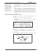
Vixel Model 335 Installation & Configuration Guide CHAPTER 3 Management Zone Settings The switch uses two types of port zoning: Overlapping and Non-Overlapping Zones. With overlapping zoning, devices on one port are not allowed to see devices on another port, yet those same devices can both see a device on a third port. Figure 3-22. Overlapping Zones In Figure 3-22, Zone 1 includes ports 1, 3, and 4, while zone 2 includes ports 2, 4 and 5. Port 4 overlaps both zones.
CHAPTER 3 Management Vixel Model 335 Installation & Configuration Guide The Zone Information page displays the current zoning configuration, the ports in each zone, the zone state, the init count, and the time duration ("up time") for the zone. The displayed settings are listed below: Setting Description Zone number The zone number on the switch (1-12). Port number(s) The port numbers that are assigned to the specified zone. Zone state The current state of the zone; either "up" or "down".
Vixel Model 335 Installation & Configuration Guide CHAPTER 3 Management To configure the overlapping ports: 1. Click Change Overlapping Zones. The Overlapping Zone 1 Information page appears with the ports available for modification. Figure 3-26. Overlapping Zone 1 Information (Configuration) Page 2. Click the appropriate check box for the two ports. If the check box is selected (checked), the two ports can communicate with one another.
Vixel Model 335 Installation & Configuration Guide Note: You can have simultaneous overlapping and non-overlapping zoning. Overlapping zoning operates in Zone 1 and non-overlapping zoning operates in Zones 2-12. CHAPTER 3 Management To view the non-overlapping zoning, click Non Overlapping. The Non Overlapping Zone Information page appears. Figure 3-27. Non-Overlapping Zone Information Page To modify the port configurations in the various zones: 1. Click Change Non Overlapping Zones.
Vixel Model 335 Installation & Configuration Guide CHAPTER 3 Management To highlight a specific zone, click the Highlight Zone drop-down box and select the desired zone. The highlighted zone displays in color. Figure 3-29.
Vixel Model 335 Installation & Configuration Guide CHAPTER 3 Management U s i n g t h e C om m a n d L i n e I n te r fa c e (C L I ) The Command Line Interface (CLI) allows you to complete several switch management tasks over Ethernet through a telnet session or through a direct serial link.
Vixel Model 335 Installation & Configuration Guide CHAPTER 3 Management Configuring the Switch The CLI enables you to configure the switch settings, policies, and zoning. A list of frequent switch configuration tasks and their commands is shown here. Refer to the provided page number for more detailed information on each configuration task. Configuration Task Change the IP parameters CLI Command co (See “Changing the Switch’s IP Parameters” on page 38.
CHAPTER 3 Management Vixel Model 335 Installation & Configuration Guide Changing the Switch’s IP Parameters To view the current switch configuration, type co at the prompt. The Configuration Menu appears: CONFIGURATION MENU 1. 2. 3. 4. IP Address Netmask Default Gateway DHCP ACTIVE VALUE 172.16.52.2 255.255.240.0 172.16.48.1 Disabled SAVED VALUE 172.16.52.2 255.255.240.0 172.16.48.1 NEW VALUE 5. Save changes and reset switch 6. Save changes and exit menu 7.
Vixel Model 335 Installation & Configuration Guide CHAPTER 3 Management Managing the Firmware To view the current firmware settings and a complete list of commands, type fw at the prompt. The Internal Firmware Versions list and Firmware Menu appear: Internal Firmware Versions: -----------------------------------------------------CURRENT: V2.01 (build 79) Mar 23 2002 00:48:59 ALTERNATE: V2.00 (build 69) Feb 27 2002 17:30:42 BOOT: V1.01 (build 55) Nov 9 2001 11:11:23 FIRMWARE MENU 1. Show versions 2.
Vixel Model 335 Installation & Configuration Guide CHAPTER 3 Management d. Type the following and press Enter. quit 4. In the terminal session window, type 1 to verify and store the new firmware. The following message appears. Clearing backup host filename.. Clearing backup host IP address.. Verifying file integrity.. Erasing flash memory.. Programming flash memory.. Verifying.. *PROGRAM LOAD SUCCESSFUL* Type fw, then type 1. The active and alternate firmware versions are displayed. 5.
CHAPTER 3 Management Vixel Model 335 Installation & Configuration Guide 6. Type fw, then type 1. The active and alternate firmware versions are displayed. 7. If the “alternate version” is anything other than the firmware you just downloaded, verify that the file is good and repeat the download. 8. If you want to activate the alternate version (the newly downloaded firmware): a. Type 2 to select the alternate version for execution on the next boot cycle. b.
CHAPTER 3 Management Vixel Model 335 Installation & Configuration Guide 4. If you want to edit any of the listed options, type the number corresponding to the desired option (community [password], severity, state, or mode) and follow the prompts. Option Description Community Sets the community string to public or private. An SNMP server has a "community string" which is like a password to get or set information.
Vixel Model 335 Installation & Configuration Guide CHAPTER 3 Management Changing the CLI/Web Password Note: If you do not remember your password, call your customer service representative. One password is used to access both the Web Manager and the Command Line Interface. You can change the password through the Command Line Interface (CLI) only. The password must be between 6 and 25 characters in length. To change the password: 1. Type pw at the prompt. 2.
CHAPTER 3 Management Vixel Model 335 Installation & Configuration Guide Policies Note: The mc command must be entered prior to issuing one of the submenu commands. You can view the current global policy settings and configure the switch to use the policies you select. Note: Before you type a command for port policies, select the desired port by typing po # (where # is the desired port number).
CHAPTER 3 Management Vixel Model 335 Installation & Configuration Guide To enable or disable a policy: 1. Enter the number for the desired policy. 2. Enter 2 to enable the policy or 3 to disable the policy. To view your changes, type mc and an updated list appears. Threshold Information Note: The Threshold settings should not be modified unless directed to do so by Vixel Customer Support.
CHAPTER 3 Management Vixel Model 335 Installation & Configuration Guide Actions Additional actions are available from the Management Agent Menu. An explanation of the actions follows: Action Description Reset switch Resets the switch. Reset hardware Resets the ASIC (control circuitry) inside the switch but not the switch itself. Reset counters Resets all or specific counters to zero.
CHAPTER 3 Management Vixel Model 335 Installation & Configuration Guide Changing the Switching Mode The Switch Menu allows you to configure the switch, view specific switch information, and turn on/off the switching mode. To activate the switch control command, type sw at the prompt. The Switch Menu appears.
Vixel Model 335 Installation & Configuration Guide Command Ports CHAPTER 3 Management Description Displays all information concerning a specific port. When a port number (e.g., 2) is entered, the default port number (1) is changed to the new port number. You can also change the port policies. To view port information, type 7 at the prompt. To see additional information for a port, enter the desired port number. Zone Displays information for the default switch's zone (e.g., 1, 2, etc.
Vixel Model 335 Installation & Configuration Guide CHAPTER 3 Management Displaying Ports The Show Port command displays all information concerning a specific port and allows you to change the port policies. To configure the currently selected port, type po at the prompt.To activate the show port command for a specific port, type po x (where x is the port number) at the prompt.
Vixel Model 335 Installation & Configuration Guide Setting CHAPTER 3 Management Description Control Enables you to configure control of the port. Select from: (2) auto – the default setting. The switch controls the port and prevents the insertion of incompatible ports which may cause disruption. (3) bypass – removes a port from the zone. Use this mode to troubleshoot ports. (4) extl-loopback – removes a port from the zone and routes the port's receive signal back through the port's transmitter.
CHAPTER 3 Management Vixel Model 335 Installation & Configuration Guide Setting Description Test before insert Before allowing a port to insert into a zone, the port is monitored for proper Loop Port State Machine (LPSM) protocols. (At least one of the devices on the port must be a Loop Initialization Master (LIM) to follow these protocols.) Overlapping zones Note: This setting should not be modified unless directed to do so by Vixel Customer Support.
CHAPTER 3 Management Vixel Model 335 Installation & Configuration Guide Changing the Switch’s Operating Speed The link speed command enables you to change the switch’s operating speed. To activate the link speed control, type lsp at the prompt. SWITCH LINK Link Link (1) Link SPEED (switch ID=14000147) speed current : 2 GBPS speed control : 2 GBPS speed next : 2 GBPS Enter either a "2" for 1 Gbps or a "3" for 2 Gbps. You must reset the switch before the speed change becomes effective.
CHAPTER 3 Management Vixel Model 335 Installation & Configuration Guide Non-Overlapping Zoning Configuration Note: Ports 11 and 12 can only be in Zone 1. The non-overlapping zones feature enables you to assign each port on the switch to one of 12 available zones. Each zone is unique which allows for 6 separate zones to function on the same switch. With non-overlapping zoning enabled, each zone is totally independent and LIPs on one zone do not affect the other zones.
CHAPTER 4 Technical Reference Technical Support 54 Troubleshooting 55 Small Form-Factor Pluggable (SFP) Issues 56 Fibre Channel References 56 Te ch ni c a l S up po rt Before contacting Customer Support, check for solutions in this guide. Contact information for Technical Support is provided in the Welcome Letter that came with your switch.
Vixel Model 335 Installation & Configuration Guide CHAPTER 4 Technical Reference Tro ub l e s h oo ti n g Some common troubleshooting situations are listed below with suggested courses of action. Situation* No LEDs are on. Recommended Action Make sure that the switch is plugged into an adequate AC power source (shown in “Operating Conditions” on page 59). Cycle power to the switch. The switch’s Fault LED is on. The Mgmt Present LED is off. The Mgmt Present LED is blinking continuously.
Vixel Model 335 Installation & Configuration Guide CHAPTER 4 Technical Reference Small Form-Factor Pluggable (SFP) Issues Items to check for common SFP-related symptoms are listed below. Problem SFP installed in one or more ports but no LEDs lit SFP installed but only yellow LED is lit Recommended Action Verify power cord is firmly seated into switch and is connected to a properly earthed receptacle (outlet). Check the Power LED to ensure switch is turned on. Re-seat the SFP.
Appendixes 57
APPENDIX A Specifications Specifications 58 Operating Conditions 59 Specifications The switch’s specifications are listed below: Number of Ports 12 Operating Rate 1.0625 or 2.125 Gbps Port Media Type SFP Enclosure 1U full-rack form factor Management Interface RS-232 or 10BaseT Ethernet Operating Mode Switching or Non-switching modes Configurability Management interface configurable Power On Self Test (POST) Yes Dimensions Approximately 17.2" x 1.72" x 14.
Vixel Model 335 Installation & Configuration Guide APPENDIX A Specifications Operating Conditions The switch must be operated in a clean, dry environment with unrestricted airflow. Air flows in through the cosmetic end and out through the business end (sometimes called the transceiver end or “back-of-box”). To avoid overheating, maintain a minimum clearance of two inches (50.8 millimeters) on each end of the switch (the cosmetic end and the business end).
CLI Console Commands APPENDIX B General Commands 60 Browse Commands 60 Action Commands 61 C on s ol e C om m a n ds All of the commands below are ordered generally by category. The format of the commands is given in the list, however, the “help” command at the command line may give even more detail. Command Syntax Action General Commands Configure co Displays information on the switch’s IP parameters: IP Address, default gateway, and netmask. You can also enable/disable DHCP.
Vixel Model 335 Installation & Configuration Guide Command APPENDIX B CLI Console Commands Syntax Action Show Hardware Menu sh Displays hardware information and versions. Show Enclosure Menu se Displays information on fan status, temperature, controller status, and management status. Show Diagnostics Menu sd Displays diagnostic registers for the default port. This includes the detector, match, control, capture and tx registers.
Vixel Model 335 Installation & Configuration Guide Command Configure Nonoverlapping Zones Syntax noz noz z:p,p,p.. z:p p.. z.. APPENDIX B CLI Console Commands Action Configures ports for non-overlapping zones. Values: z = zone number 1 to 12 p = port number 1 to 12 Note: Unspecified ports are placed into zone 1. Each port must be in one non-overlapping zone only. Ports on a zone may be separated by a comma or spaces.
APPENDIX C Event Messages The event messages are listed by reference number.
APPENDIX C Event Messages Vixel Model 335 Installation & Configuration Guide Ref Event Message 132 Zone up then down The zone state has cycled through the “up” and “down” states several times. Current zone state (at the time of this message) is down. --- Warning 133 Zone down then up The zone state has cycled through the “up” and “down” states several times. Current zone state (at the time of this message) is up.
APPENDIX C Event Messages Vixel Model 335 Installation & Configuration Guide Ref Event Message Meaning Action Severity 203 Port switch connect overflow A number of stalls have occurred in a specific amount of time. --- Info 204 Port switch stall An instance occurred where two devices could not disconnect communications with one another. --- Info 205 Port switch bad open A device is trying to send an --OPN but it cannot be delivered.
APPENDIX C Event Messages Vixel Model 335 Installation & Configuration Guide Ref Event Message Meaning Action Severity 272 Daytime mode changed The current daytime mode (none, user, server) has changed. --- Info 273 Daytime server IP Address changed The IP Address for the daytime server has changed. --- Info 274 Daytime server update period changed The amount of time the daytime servers waits between updates has changed.
Loop ID—AL_PA Cross References APPENDIX D Arbitrated Loop Physical Addresses AL_PA Loop ID AL_PA Loop ID AL_PA Loop ID (hex) (hex) (decimal) (hex) (hex) (decimal) (hex) (hex) (decimal) EF E8 E4 E2 E1 E0 DC DA D9 D6 D5 D4 D3 D2 D1 CE CD CC CB CA C9 C7 C6 C5 C3 BC BA B9 B6 B5 B4 B3 B2 B1 AE AD AC AB AA A9 A7 A6 A5 00 01 02 03 04 05 06 07 08 09 0A 0B 0C 0D 0E 0F 10 11 12 13 14 15 16 17 18 19 1A 1B 1C 1D 1E 1F 20 21 22 23 24 25 26 27 28 29 2A 0 1 2 3 4 5 6 7 8 9 10 11 12 13 14 15 16 17 18 19
APPENDIX E Glossary AL_PA or Arbitrated Loop Physical Address A one-byte value used to identify a port in an Arbitrated Loop topology. The value of the AL_PA corresponds to bits 7:0 of the 24-bit Native Address Identifier. Arbitrated Loop A Fibre Channel topology structured as a loop and requiring a port to successfully arbitrate prior to establishing a circuit to send and/or receive frames. Arbitration The process of selecting one respondent from a group requesting service at the same time.
Vixel Model 335 Installation & Configuration Guide APPENDIX E Glossary Non-overlapping Zones Enables the switch to be divided into separate environments, where each environment sustains a complete 127-device AL_PA space. Open An Arbitrated Loop protocol used to establish a switch circuit. Overlapping Zones Devices on one port are not allowed to see devices on another port, yet those same devices can both see a device on a third port.
Index A G AL_PA-Loop ID Cross References.... 67 attaching devices ................................ 5 glossary............................................ 68 C cascading switches ............................. 9 Command Line Interface (CLI) ........ 36 configuring switch .................... 37 configuring switch information. 38 configuring traps ...................... 41 connecting to ............................ 36 DHCP requests ......................... 38 downloading firmware .............
Index Vixel Model 335 Installation & Configuration Guide S W setup .................................................. 5 SFPs ................................................... 4 shipped contents .............................. 11 specifications ................................... 58 switch ................................................ 5 attaching devices......................... 5 cascading .................................... 9 changing the password ............. 43 CLI .............................