INSTRUCTION MANUAL Outdoor Day/Night Camera Wide C-CV454D-3 CU Standard C-CV454D-9 CU Tele C-CV454D18 CU Thank you for purchasing TOA Outdoor Day/Night camera: Wide, Standard, or Tele. Please carefully follow the instructions in this manual to ensure long, trouble-free use of your equipment.
TABLE OF CONTENTS 1. SAFETY PRECAUTIONS ............................................................................... 3 2. GENERAL DESCRIPTION ............................................................................. 5 3. HANDLING PRECAUTIONS .......................................................................... 5 4. NOMENCLATURE ............................................................................................. 6 5. INSTALLATION AND CONNECTIONS ..........................................
1. SAFETY PRECAUTIONS • Before installation or use, be sure to carefully read all the instructions in this section for correct and safe operation. • Make sure to observe the instructions in this manual as the conventions of safety symbols and messages regarded as very important precautions are included. • We also recommend you keep this instruction manual handy for future reference.
CAUTION Indicates a potentially hazardous situation which, if mishandled, could result in moderate or minor personal injury, and/or property damage. • Leave the installation of the unit to your TOA dealer because the installation requires expert experience and skills. The unit may fall off if incorrectly installed, resulting in possible personal injury. • Do not stand or sit on, nor hang down from the unit as this may cause it to fall down or drop, resulting in personal injury and/or property damage.
2. GENERAL DESCRIPTION The TOA C-CV454 series are outdoor Day/Night cameras equipped with a 1/3" CCD. A lineup of cameras with three types of lenses, Wide, Standard, and Tele allows accurate monitoring over a wide range from near to distant subjects depending on the installation location. Noise reduction function enables clear image to be viewed in lower noise under poor lighting conditions.
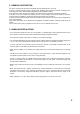
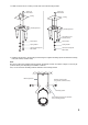
4. NOMENCLATURE [Appearance] 6 7 1 2 3 5 4 [View with sunshade, front cover, and mounting bracket detached] 8 9 10 11 12 13 15 OFF HEAD FIXING [View with waterproof cap detached] 16 ON F.
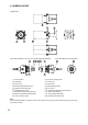
5. INSTALLATION AND CONNECTIONS [Ceiling mounting example] [Wall mounting example] Camera mounting bolt M8 or W3/8 Bracket mounting bolt with washer, stainless steel (accessory) WARNING Safety wire mounting hole Install the unit only in a location that can structurally support the weight of the unit and the mounting bracket. Doing otherwise may result in the unit falling down and causing personal injury and/or property damage. Note Install a safety wire as needed.
[Example 1: Mounting to a ceiling or wall] [Example 3: Mounting to a ceiling or wall] If only fine adjustment of camera angle is required; Camera mounting bolt M8 or W3/8 Camera mounting bolt M8 or W3/8 [Example 2: Mounting on a wall] If angle which Example 1 can not cover is required; Camera mounting bolt M8 or W3/8 8 Anti-rotation screw (tapping screw) Note Installing the mounting bracket using only one camera mounting bolt may cause the bracket to rotate or the bolt to come loose.
2. Install an anchor nut into a ceiling or a wall, then secure the mounting bracket. Anchor nut M8 or W3/8 Ceiling Mounting bracket Anchor nut M8 or W3/8 Ceiling Mounting bracket Anti-rotation screw (tapping screw) Plain washer Plain washer Spring washer Spring washer Camera mounting bolt M8 or W3/8 Camera mounting bolt M8 or W3/8 3. Install the camera unit to the mounting bracket using the supplied insulating spacers and Bracket mounting bolts (with washer, stainless steel).
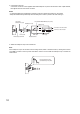
4. Connect the connector. Connect the connector of the supplied cable with waterproof cap to the camera unit's video output terminal, then tighten the lock screw of the connector. Notes • To meet the waterproof requirements, insert the connector in place until it will not go any further. • Wrap self-adhesive butyl rubber tape around cable joints in order to prevent rain from soaking in. Connector (waterproof type) UL 1095#22 Black/White (non-polar) Waterproof cap Cable joints Connect to the AC mains.
6. Connect the camera unit. Connect the camera unit to both the monitor and the power supply as illustrated below. Notes • If the Video output is not terminated at 75Ω, camera images are not properly displayed. Make sure that the output has been terminated at 75Ω at the connected monitor or switcher. • The microphone unit cannot be used for the C-CV454 series.
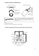
6. ADJUSTMENT 1. After completing camera unit installation and connections, remove both the sunshade and front cover. [Removing sunshade] [Removing the front cover] Loosen two sunshade fixing screws. Turn the front cover in the direction indicated by the arrow to remove. Turn the sunshade, then extract it. Front cover 2. Connect the camera’s monitor output terminal to the monitor. Note: The camera will not operate if the monitor output terminal is connected to the camera drive unit. 3.
5. Adjust the camera angle. • Camera's orientation can be adjusted with the camera mounting and bracket mounting bolts loosen. • Adjust the inclination of image so that the projection of the camera faces upward by loosening a camera head fixing screw and turning the camera head. After adjustment completion, retighten the camera head fixing screw. Note Horizontal camera angle cannot be adjusted if the camera unit is installed as shown in [Example 3] on page 8.
7. After completing all the adjustments, disconnect the cable connected to the monitor output terminal in Step 2. 8. Tighten both the camera mounting and bracket mounting bolts, then replace the front cover. Note: If the front cover is not secured enough, waterproof effect is reduced, causing unit failure. 9. Insert the sunshade from the front side of the camera unit as shown below, then secure it with two sunshade fixing screws.
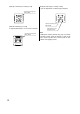
7. ABOUT MODE SETTING SWITCH Set each switch to the position that provides the best picture reproduction. OFF OFF ON 1/60 ATW D/N AWB COLOR IRIS L H ON 1/60 F.ADJ BLC 1/100 ATW D/N AWB COLOR F.ADJ BLC 1/100 1: Focus adjustment switch 2: Backlight compensation switch 3: Flickerless switch 4: ATW/AWB selection switch 5: Mode selection switch Mode Setting Switch (Factory-preset setting) 7.1. Focus adjustment switch: Set to “ON” position when adjusting focus.
7.4. ATW/AWB selection switch: Set the white balance operation. OFF ON ATW: Set to “OFF” position during normal use. The camera's white balance automatically changes as an object's color temperature varies. OFF ON AWB: Set to “ON” when the difference between the displayed color and actual color is annoying. Shoot the white object, then turn the switch ON. The camera operates on the initially set white balance even if an object's color temperature changes. 7.5.
8. TROUBLESHOOTING Possible Cause Symptom No camera image dis- Cables are not correctly connected. played on the monitor. BNC plugs are not correctly soldered. Camera image is not Camera lens does not focus properly. clear. Lens is dirty. Image black level of the monitor is not correctly adjusted. When the subject The subject that was brought into becomes dark, it could focus when it is bright could be out of focus when it grows dark. (Effect of be out of focus.
9. SPECIFICATIONS Model No.
• Accessories Mounting bracket ..................................................................................... 1 Cable with waterproof cap (2 m) .............................................................. 1 Bracket mounting bolts (with washer, stainless steel) ............................. 2 Insulating spacer ......................................................................................
URL: http://www.toa.