QUICK MANUAL DIGITAL VIDEO RECORDER C-DR091 CU Series C-DR161 CU Series Thank you for purchasing TOA Digital Video Recorder. Please carefully follow the instructions in this manual to ensure long, trouble-free use of your equipment.
TABLE OF CONTENTS 1. SAFETY PRECAUTIONS .................................................................................. 3 2. NOMENCLATURE AND FUNCTIONS [ Front ] ....................................................................................................................... 6 [ Rear ] ....................................................................................................................... 7 3. CONNECTIONS ..............................................................................
1. SAFETY PRECAUTIONS • Before installation or use, be sure to carefully read all the instructions in this section for correct and safe operation. • Make sure to observe the instructions in this manual as the conventions of safety symbols and messages regarded as very important precautions are included. • We also recommend you keep this instruction manual handy for future reference.
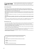
CAUTION Indicates a potentially hazardous situation which, if mishandled, could result in moderate or minor personal injury, and/or property damage. When Installing the Unit • Never plug in nor remove the power supply plug with wet hands, as doing so may cause electric shock. • When unplugging the power supply cord, be sure to grasp the power supply plug; never pull on the cord itself. Operating the unit with a damaged power supply cord may cause a fire or electric shock.
CU version complies with Part 15 of the FCC Rules. Note This equipment has been tested and found to comply with the limits for a Class A digital device, pursuant to Part 15 of the FCC Rules. These limits are designed to provide reasonable protection against harmful interference when the equipment is operated in a commercial environment.
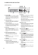
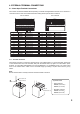
2. NOMENCLATURE AND FUNCTIONS [ C-DR161 Series Front ] 5 3 7 9 12 DVD ARCHIVE KEY LOCK 1 9 2 10 3 11 4 12 5 13 6 14 7 15 8 16 PRIORITY REC MONITOR 1 BUZZER STOP/ ALARM RESET ZOOM SEARCH MENU/ ENTER MULTI SCREEN SEQUENCE REC FAILURE HD FULL MONITOR 2 DIGITAL VIDEO RECORDER C-DR161 2 (1) Power key [ ] Pressing the Power key changes the Digital Video Recorder's mode from standby to operation mode.
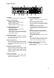
[C-DR161 series Rear] 18 23 RM TERMINATION ON OFF IN 1 2 3 4 5 6 7 8 9 10 11 12 13 14 15 16 1 2 RM IN-A DISK ARRAY OUT VIDEO AC MAINS LINK 1 2 MONITOR OUT IN OUT AUDIO RS-232C 1 G 2 9 G 10 G 3 G 11 G ALARM IN 4 G 5 G G 12 G 13 6 G 14 G 7 G 15 8 G PRIORITY NC IN G G 16 G 1 G G 2 CAMERA + G CONTROL OUT G 3 G + RM IN-B G - 4 G IN RM OUT-B + G TIME SYNC G OUT G SER.
3.
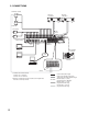
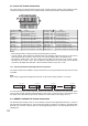
4. EXTERNAL TERMINAL CONNECTIONS 4.1. Alarm Input Terminal Connections The number of terminals available differs depending on whether the Digital Video Recorder is a 9-channel or a 16-channel version. Refer to the table below when making alarm input terminal connections.
4.2. Control I/O Terminal Connections The control input and output terminals include: priority recording terminal, camera control terminal, remote controller input/output terminals, control output terminal, and time synchronization input/output terminals.
5. DIGITAL VIDEO RECORDER ACTIVATION AND TERMINATION 5.1. Recorder's Activation 1. Insert the power supply plug. The Recorder is placed in standby mode. The power key flashes at about 5-second intervals while in standby mode. Power key LED indicator Distinguishes Note Do not pull out the power supply plug while the Power key is light green. Ensure that the Recorder is in the standby mode when pulling out the power supply plug.
6.2.
To previous page Main menu item Menu item SYSTEM SETTING PLAY DISK Setting item HD REMAINING TIME BUZZER I/O TERMINAL MODE INPUT MODE OUTPUT MODE CTRL OUT TERMINAL PRIORITY REC ALARM REC MOTION REC HD FULL HD ERROR VIDEO LOSS FAN FAILURE SECURITY SETTING OPERATION LEVEL 1, 2, 3 CAMERA PRESET SETTING USB KEY LEVEL CAMERA PROTOCOL PRIORITY REC OPERATION LEVEL 3 CAMERA BIT RATE REMOTE ACCESS LIMIT RS232C BIT RATE LOGOUT INTERVAL RS232C FLOW CTRL RS232C RESPONSE CONTROLLER BIT RATE CONTROLLE
7. INITIAL SETTINGS Be sure to perform the following settings before using the Digital Video Recorder. Failure to do so may lead to incorrect operation of each function. • DVR-ID setting (When cascade-connecting) Note: When cascade-connecting the Digital Video Recorders, set the DVR-ID first. Otherwise, the Menu screen is not displayed. • Clock settings • Hard disk initialization • Auto-Recording settings 7.1.
5. Move the cursor with the [ ] and [ ] keys, select "YES," then press the Menu key. The message requesting a reboot is displayed. Note There is no need to reboot the DVR if not synchronizing using the NTP server, though the message requesting a reboot is displayed after the clock setting has been saved. (The changed setting is reflected in the device without rebooting the DVR.) 6. Move the cursor with the [ ] and [ ] keys to select "NO," then press the Menu key. The display reverts to the main menu screen.
7.4. Auto-Recording Settings Recordings are normally performed according to the preprogrammed schedule. Therefore, perform schedule or group settings when making auto-recording. 7.4.1. Schedule setting Set the schedule (Day, Start time, and End time) for each group to operate. Menu key Menu key 1. Hold down the Menu key for 2 seconds or more. The main menu screen is displayed. 2. Select "REC SETTING," then press the Menu key. The Recording setting screen is displayed. 3.
7.4.2. Setting the group Perform individual settings such as Normal recording and Alarm Event recording for Group A - F.
8. MONITOR DISPLAY 8.1. Full-Screen Display Pressing the Camera Selector key while in live or playback mode displays the selected camera output on the full screen. L 1 L 2 L 3 L 3 SA T J AN / 0 1 / 0 5 0 : 0 0 : 0 0 L 4 L 5 L 6 L 7 L 8 L 9 SA T J AN / 0 1 / 0 5 0 : 0 0 : 0 0 Press the Camera Selector key No. 3. AB AB 8.2.
8.3. Sequence Display Camera live images are displayed in sequential order when the Sequence key is pressed while in live mode. Viewing intervals and cameras to be displayed can be set on the menu screen. Sequence key lights continuously during Sequence display.
9. RECORDING 9.1. Priority Recording Priority recording is given higher priority over Auto recording. Use this recording mode to check recording details when, for example, a suspicious person intrudes or when making recording outside the scheduled time period. In the Priority Recording settings, the following settings can be made for individual cameras: recording ON/OFF, recording rate, picture quality and audio ON/OFF. 9.1.1. How to perform priority recording 1.
10. PLAYBACK 10.1. Playback Press the Play [ ] key. Recorded images are played back. The Playback key lights green, displaying the playback screen. When playback is performed again, playback begins from the time at which it last stopped. 10.2. Reverse playback Press the Reverse Play [ ] key. Plays back recorded images in reverse chronological order. The Reverse Play key lights green, displaying the reverse playback screen.
10.7. Pause 1. Press the Pause [ ]( ) key during forward or reverse playback. Playback is temporarily stopped and the key lights green. 2. To perform playback again, press the Play [ ] key or Reverse Play [ Pause mode is cancelled and forward or reverse playback begins again. ] key. 10.8.
11. SEARCH 11.1. Date/Time Search Entering the date and time to perform a search displays all camera images recorded closest to the designated time in freeze-frame on the 16-segment (or 9-segment) split screen display. If no recording is made on the designated date and time, the date and time closest after the designated date and time is displayed. The oldest and newest times for recorded data are displayed, so please enter dates and times occurring between these. 1. Press the Search key.
12. ARCHIVE The Digital Video Recorder is equipped with an archive function that transfers image data recorded on the hard disk to DVD-R disk (available only to models with DVD drives) or USB memory. Camera image data designated between start position and end position can be archived. Since dedicated viewer software is also downloaded at the same time, archived images can be easily played back on a PC. Note Archive operation can be performed only at the operation level 1.
13.
* 0 dB = 1V Model Power Source Power Consumption Image Compression Video Format Recording Medium Video Input Video Output Monitor Output Link Input Audio Recording System Audio Input Audio Output Screen Display Picture Quality Pixels Recording Rate Pre-Recording Post Alarm Recording Date/Time Motion Detect Search Function Alarm Input Control Output Priority Recording Input Time Synchronization Input Time Synchronization Output Camera Control Remote Control Disk Array Communication Function Other Functio
* 0 dB = 1V Model Power Source Power Consumption Image Compression Video Format Recording Medium Video Input Video Output Monitor Output Link Input Audio Recording System Audio Input Audio Output Screen Display Picture Quality Pixels Recording Rate Pre-Recording Post Alarm Recording Date/Time Motion Detect Search Function Alarm Input Control Output Priority Recording Input Time Synchronization Input Time Synchronization Output Camera Control Remote Control Disk Array Communication Function Other Functio
* 0 dB = 1V Model Power Source Power Consumption Image Compression Video Format Recording Medium Video Input Video Output Monitor Output Link Input Audio Recording System Audio Input Audio Output Screen Display Picture Quality Pixels Recording Rate Pre-Recording Post Alarm Recording Date/Time Motion Detect Search Function Alarm Input Control Output Priority Recording Input Time Synchronization Input Time Synchronization Output Camera Control Remote Control Disk Array Communication Function Other Functio