INTERCOM SYSTEM TOA EXES-1000 INTERCOM SYSTEM Central Control Unit CCU-11B INSTALLATION HAND BOOK TOA ELECTRIC CO., LTD.
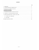
CONTENTS Page 1. Introduction ................................................................ 2 2. Functions which Require Additional Units . . . . . . . . . . . . . . . . . . . . . . . . . . . . . . . . . . . . . . . . 2 3. Precautions for Installation of CCU-11B . . . . . . . . . . . . . . . . . . . . . . . . . . . . . . . . . . . . . . . . . . . 3 4. Initial CCU-11B Set Up . . . . . . . . . . . . . . . . . . . . . . . . . . . . . . . . . . . . . . . . . . . . . . . . . . . . . . . 4 5.
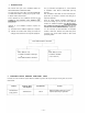
1. INTRODUCTION This manual forms part of the Installation Manual for For (1) Connections of Equipment, etc., refer to Manual TOA INTERCOM SYSTEM EXES-1000. of Installation Hand Book of EXES-1000 (EX-110) You may add to the CCU-11B to your TOA INTERCOM Exchange. SYSTEM EXES-1000, according to your specific needs, This "Installation Hand Book of CCU-11B" deals prin- to obtain various other functions.
3. PRECAUTIONS FOR INSTALLATION OF CCU-11B. Please read following instructions carefully to ensure 6. Even if you do not need programming functions, be proper operation of the CCU-11B. sure to carry out initial programming and registration at station No. 11 when you install the new unit. 1. Be careful about damage by static electricity as the Otherwise, CCU-11B incorporates CMOS IC's. Do not touch com- some other functions may not work properly. ponents and connectors. 7.
4 INITIAL CCU-11B SET UP Make sure that you have turned off the AC power switch. Remove the CCU card from the card rack of exchange. Set mini-jumper on the CCU card to "BATT. ON" position. Set function selection DIP switches (SW-A & SW-B) on the CCU card for required functions. Insert the CCU card into the card rack of exchange, and make necessary connection correctly. Turn on the AC power switch of exchange. Turn on PROGRAM switch on the CCU card.
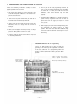
5 DIP SWITCH FOR FUNCTION SELECTION ON CCU-11B The DIP switches on the CCU-11B allow selection of the following functions; A. All Call Paging and Response E. PTT Control B. Call Holding/Call Transfer F. Priority and Executive Priority C. Calling Tone Duration G. Remote Control D. Time Interval Adjustment before All Call Paging H. Continuous Calling Tone Switches 1: BATT. OFF 2: BATT.
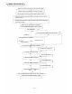
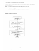
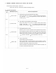
6. STATION NO. 11 PROGRAMMING FOR EACH FUNCTION Use station #11 for programming of "Continuous Calling Tone", "Secretary Transfer", "Master/Sub-Relationship" and/or "Executive Priority" functions. Remarks: 1. In the event of failure to touch keys for correct dialing, privacy tone will be sound. Re-start from the beginning. 2. When All Call Paging is used, the registration to the station #10 can not be done. The following shows how to register the functions: 1.
2. Secretary Transfer New registration ? Ascertain holding tone Station Number of executive Station Number of secretary All registration finished ? Release ? Ascertain holding tone Station Number of executive Station Number of executive Release finished ? Return 3.
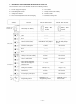
7. REMOTE CONTROL RELAYS (RY1 & RY2) ON CCU-11B Remark: Relay Control Capacity: 30VDC, 2A Relays (RY1 & RY2) on CCU-11B are available for following functions. Relay No. DIP Switch Position Functions and Operations A SW-A-3 "OFF" Door Remote Control (One-shot-Make Relay Output) Every master station can be used as a remote control device for door opening. Touch dial gives approximately 4 seconds make-contact for the door opening.
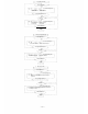
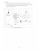
7-2. Connections A. Connect 4-pin connector from TBM-11 (Terminal module) to P2 connection socket on the CCU-11B. B. RM 1 terminals on TBM-11 are for the door remote control relay contacts and RM2 terminals on TBM-11 are for the power ON/OFF remote control or press to talk remote control relay contacts. (Please refer to the following diagram.) DOOR YEL ORG RM1 AC RM2 AC RED BRN In the case of power ON/OFF remote control.
8. PROGRAMMING LIST FOR FUNCTIONS Use these tables to keep a record of those functions assigned to each station. Function Table for Stations Name 10 11 12 13 14 15 16 17 18 19 20 21 22 23 24 25 26 27 28 29 30 31 32 33 34 35 36 37 38 39 40 41 — 10 — Master Station No. Secretary Station No.
TOA ELECTRIC CO.,LTD.