EXES-5000 CPU-56 For INTERCOM SYSTEM TOA EXES-5OOO INTERCOM SYSTEM Central Processing Unit CPU-56 INSTALLATION HAND BOOK TOA ELECTRIC CO., LTD.
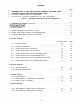
CONTENTS Page INTRODUCTION TO THE INSTALLATION MANUAL FOR EXES - 5000 3 FUNCTIONS WHICH REQUIRE ADDITIONAL UNITS 4 6 8 TIELINE CONNECTION OF EXCHANGES WIRING FOR TIELINE CONNECTION OF THE EXCHANGES PART 1. Operating of CPU Unit and No. 200 Programming 1. Precautions for Installation of CPU-56 2. Initial CPU-56 set up 10 3. 13 11 Trouble Shooting 4. CPU-56 DIP-Switches for Function Selection 17 5. Function Code Table for Station No. 200 Programming 18 6. Station No.
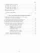
Page 7. Programming Record for Functions. . . . . . . . . . . . . . . . . . . . . . . . . . . . . . . . . . . . . . . . . . . . 3 4 Function Table for Stations ( 1 ) . . . . . . . . . . . . . . . . . . . . . . . . . . . . . . . . . . . . . . . . . . . . . . . . . . 3 4 Function Table for Stations Function Table for Stations Function Table for Stations ( 2 ) . . . . . . . . . . . . . . . . . . . . . . . . . . . . . . . . . . . . . . . . . . . . . . . . 35 (3)..........................................
INTRODUCTION TO THE OPERATION INSTALLATION MANUAL FOR EXES-5000 This manual forms part of the Installation Manual for TOA INTERCOM SYSTEM EXES-5000. You may add the CPU-56 to your TOA INTERCOM SYSTEM EXES-5000, according to your specific needs, to obtain various other functions. Correct operation of these additional functions are not necessarily available only by connection of the additional equipments/devices.
FUNCTIONS WHICH REQUIRE ADDITIONAL UNITS (When the Exchanges are not connected by means of Tie-line.) Those functions of the CPU-56 which require either the addition of specific units or processing in existing units are as mentioned below. Before installation and adjustment of equipment, make sure to check your system. (For Data Transmitting and Receiving units, refer to Part 2. "Function Selection for Data Transmitting and Receiving units" Page 43.) Additional Equipment Required Unit Model Nos.
FUNCTIONS WHICH REQUIRE ADDITIONAL UNITS (When the Exchanges are connected by means of Tie-line.) Those functions of the CPU-56 which require either the addition of specific units or processing in existing units are as mentioned below. Before installation and adjustment of equipment, make sure to check your system. (For Data Transmitting and Receiving units, refer to Part 2. "Function Selection for Data Transmitting and Receiving units" Page 43.) Additional Equipment Required Unit Model Nos.
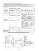
TIELINE CONNECTION OF THE EXCHANGES 1. Function of the Central Processing Unit CPU-56 To make communications between exchanges Exchange A Exchange B possible in the EXES-5000 system, the CPU-56 and the Tieline Unit TI-52 are required in addition to the exchange EX-510 or the EX-520. The TI-52 is the interface unit for transmitting and receiving audio signals and dial data signals between the exchanges.
2.
4. Reduction of the number of stations and paging zones which results from the use of the Tieline Unit TI-52. 1. Mounting one (1) piece of the TI-52 decreases the number of the LMU-52A (the 7th or the 15th LMU-52A) by one (1). 2. Unless the PIU-52A is used, the system can have up to 8 more stations by placing an LMU-52A in the 8th or the 16th position. 3. When the system uses the tieline function, the second unit of the PIU-52A (paging zones 8 - 15) cannot be used. Note.
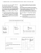
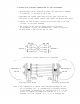
WIRING FOR TIELINE CONNECTION OF THE EXCHANGES Each exchange can be connected by means of a cable with a diameter of 0.65mm for a distance of up to 2km. Regarding the tieline links which are not used, turn off the DIP switch of each unused tieline link inside the Tieline Unit TI-52. Connect "T" line (2 wires) of the 4 wires of each link to "R" line (2 wires) of the other exchange. The 2 wires of the "T" line and "R" line have no polarity. If the BOX-064 is used, its terminals No.
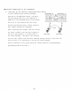
2. Wiring for tieline connection of 3 exchanges Exchange A Exchange C Exchange B Note 2. Be sure to connect TL (link No. 0,1,2,3) to TH (link No. 4,5,6,7) between the exchanges. Connection of TH to TH or TL to TL will lead to failure of proper operation of the system. Note 3. Switching arrangements of DIP switches (E-l, E-2, E-3) in the CPU-56 make each exchange to be of "EX-1" or "EX-2A" or "EX-2B" or "EX-3A" or "EX-3B" or "EX-3C" type.
3.
E x c h a n g eA Exchange A BOX-064 J7 YR-801 for tie-line YR-801 for stations Exchange B – 12 – Exchange B BOX-064 J7 YR-801:Junction cable Exchange C BOX-064 J7 YR-801 for tie-line Exchange C YR—801 for stations Terminal board BOX-064X2 The cables between Terminal board BOX-064X2 YR-801 for stations 4.
PART 1. OPERATION OF CPU UNIT AND NO. 200 PROGRAMMING 1. PRECAUTIONS FOR INSTALLATION OF CPU-56 Please read the following instructions carefully to ensure proper operation of the CPU-56. 1. Be careful about damage by static electricity as the CPU-56 incorporates CMOS IC's. Do not touch components and connectors. 2. Turn off the AC power switch when you take out or insert the CPU-56 unit, or any other unit. 3. Always insert the CPU-56 unit into the "CPU" slot.
2. INITIAL CPU-56 SET UP Make sure that you have turned off the AC power switch. Connect the exchange, terminal boards and stations. Are Data Transmitting and Receiving Units connected ? YES Remove CPU-56 from the exchange. Set mini-jumper, (JP1) for battery from OFF to ON position. Set function selection switches (SW-A ~ SW-E) for required functions. Insert the CPU-56 into the exchange. Put all 4 "link select" switches of the HCU unit upward. (Link No.15) Switch on the exchange.
Dial operation from station No. 200. — Initial programming of the exchange — Dial the Following: 1. Dial tone will be heard (Station No.200 becomes a programming station) 2. 10 times 3. 10 times 4. 10 times 5. 10 times 6. 10 times Confirmation tone will be heard. (Clears function group A) Confirmation tone will be heard. (Clears function group B) Confirmation tone will be heard (Clears function group C) Confirmation tone will be heard. (Clears function group D) Confirmation tone will be heard.
3. TROUBLE SHOOTING 3-1 Check of ROM & NMOS-RAM - No calls on the system. 1. Put the 4 "LINK SELECT" switches of the HCU upward (Link No. 15 SELECT) and switch on the AC power of the exchange. 2. If there is no error, no HCU indication lamps will light. 3. In the event of a memory error, the lamps may light as shown in the example of Fig. 1. 4. The error indications will remain on until you use Link No. 15 for communications. Example Error ROM • RAM Chip No. No.1 and No.2 out of 6 pcs ROMs error.
3-4. Dial receiving test If you place all "LINK SELECT" switches (1 ~ 4) of SW-A on the CPU-55 in "OFF" position, conversation is impossible but the dial code from each station is indicated on the LED's of the PIU as dialed. Use this to find the cause of any fault of receiving dial information. DIP switches (SW-A of the CPU) PRIVACY PRESS DIGITS DIALED RELEASE (PTT) PRIVACY Fig. 2 ON ON PIU LED No. Fig. 3 Dial code indication 3-4 The order of link usage.
3-6. The order of Tie Line link usage. The Tieline Link Number which is used in calls between exchanges is not directly indicated, but you can possibly get it from the link number which is indicated on the HCU-52. When one Tieline Link brings up some problems which cause the system not to work properly, try to find which link number is causing the problems from the indication on the HCU-52 of the exchange making the call.
Reference for Connection Link Number between DLU and TI Link Exchange which calls DLU Link No Exchange which is called TI Tieline Link Number Tieline Link Notice: If the TI Tieline Link which correspond with the DLU Link No is already busy, then, the next Tieline Link is automatically used.
4. CPU-56 DIP SWITCH FUNCTION SELECTION Functions Switch On Off Activate Not Activate 1 Sec. None Activate Not Activate Link Selection ; Link No. 0 ~ 3 Link Selection ; Link No. 4 ~ 7 SW-A Link Selection ; Link No. 8 ~ 11 Link Selection ; Link No.
D C A Function Group 5. (1/0) 82 Called Group No.(s) (Plural) Paging Group No.(s) (Plural) Paging zone No. of paged group (00~21) (1~8) (l~8) Last Station No. of the Group Last Station No. of the Group Last Station No. of the zone – 21 – Programming 3rd Parameter Calling Group No. (1~8) First Station No. of the Group Group No. (1~8) 72 81 First Station No. of the Group First Station No. of the zone Master Station No. Secretary Station No. ON/OFF Group No. (1~8) Zone No.
6. STATION NO. 200 PROGRAMMING FOR EACH FUNCTION 6-1 EXECUTIVE PRIORITY (FUNCTION CODE 50) EXECUTIVE PRIORITY Step 1 Touch Function Code New Registration ? Executive Station No. ON Touch Executive Station No. ON Touch Confirmation tone NO New Registration finished ? YES Release ? Executive Station No. OFF Touch Executive Station No. OFF Touch Confirmation tone Release finished ? Return NOTES 1. To register all stations at one time, 3. Re-start at Step 1 when mis-dialing occurs.
6-2 CONTINUOUS CALLING TONE (FUNCTION CODE 51) CONTINUOUS CALLING TONE Step 1 Touch Function Code New Registration ? Continuously Called Station No. ON Touch Continuously Called Station No. ON Touch Confirmation tone New Registration finished ? Release ? Continuously Called Station No. OFF Touch Continuously Called Station No. OFF Touch Confirmation tone Release finished ? Return NOTES 1. To register all stations at one time, 3. Re-start at Step 1 when mis-dialing occurs.
6-3 STATIONS ALLOWED ACCESS TO ALL CALL (FUNCTION CODE 52) STATIONS ALLOWED ACCESS TO ALL CALL Step 1 Touch Function Code New Registration ? Allowed Station No. ON Touch Allowed Station No. ON Touch Confirmation tone New Registration finished ? Release ? Allowed Station No. OFF Touch Allowed Station No. OFF Touch Confirmation tone Release finished ? Return NOTES 1. To register all stations at one time, 3. Re-start at Step 1 when mis-dialing occurs. (All other registrations remain valid.
6-4 STATIONS ALLOWED ACCESS TO CONFERENCE (FUNCTION CODE 53) STATIONS ALLOWED ACCESS TO CONFERENCE Touch Function Code New Registration ? Allowed Station No. ON Touch Allowed Station No. ON Touch Confirmation tone New Registration finished ? Release ? Allowed Station No. OFF Touch Allowed Station No. OFF Touch Confirmation tone Release finished ? Return NOTES 1. To register all stations at one time, 3. Re-start at Step 1 when mis-dialing occurs. (All other registrations remain valid.
6-5 STATIONS ALLOWED ACCESS TO ONE SHOT MAKE OUTPUT (FUNCTION CODE 56) STATION ALLOWED ACCESS TO ONE SHOT MAKE OUTPUT Step 1 Touch Function Code New Registration ? Allowed Station No. ON Touch Allowed Station No. ON Touch Confirmation tone New Registration finished ? Release ? Allowed Station No. OFF Touch Allowed Station No. OFF Touch Confirmation tone Release finished ? Return NOTES 3. Re-start at Step 1 when mis-dialing occurs. 1.
6-6 STATIONS ALLOWED ACCESS TO MAKE/BREAK OUTPUT (FUNCTION CODE 57) STATIONS ALLOWED ACCESS TO MAKE/BREAK OUTPUT Step 1 Touch Function Code New Registration ? Allowed Station No. ON Touch Allowed Station No. ON Touch Confirmation tone New Registration finished ? Release ? Allowed Station No. OFF Touch Allowed Station No. OFF Touch Confirmation tone Release finished ? Return NOTES 1. To register all stations at one time, 3. Re-start at Step 1 when mis-dialing occurs.
6-7 STATIONS ALLOWED ACCESS TO 8 SELECTABLE (OR DECIMAL) OUTPUT (FUNCTION CODE 58) STATIONS ALLOWED ACCESS TO 8 SELECTABLE (OR DECIMAL) OUTPUT Step 1 Touch Function Code New Registration ? Allowed Station No. ON Touch Allowed Station No. ON Touch Confirmation tone New Registration finished ? Release ? Allowed Station No. OFF Touch Allowed Station No. OFF Touch Confirmation tone Release finished ? Return NOTES 3. Re-start at Step 1 when mis-dialing occurs. 1.
6-8 STATIONS ALLOWED ACCESS TO 4 DECIMAL DIGITS OUTPUT (FUNCTION CODE 59) STATIONS ALLOWED ACCESS TO 4 DECIMAL DIGITS OUTPUT Step 1 Touch Function Code New Registration ? Allowed Station No. ON Touch Allowed Station No. ON Touch Confirmation tone New Registration finished ? Release ? Allowed Station No. OFF Touch Allowed Station No. OFF Touch Confirmation tone Release finished ? Return NOTES 3. Re-start at Step 1 when mis-dialing occurs. 1.
6-9 SECRETARY TRANSFER (FUNCTION CODE 60) Registration of Call Forwarding SECRETARY TRANSFER Step 1 Touch Function Code New Registration ? Executive Station No. Secretary Station No. Touch Executive Station No. Secretary Station No. Touch Confirmation tone New Registration finished ? Release ? Executive Station No. Executive Station No. Touch Executive Station No. Executive Station No. Touch Confirmation tone Release finished ? Return NOTES 3) Station No.
6-10 MASTER/SUB RELATIONSHIP (FUNCTION CODE 61) MASTER/SUB RELATIONSHIP Step 1 Touch Function Code New Registration ? Sub Station No. Master Station No. Touch Sub Station No. Master Station No. Touch Confirmation tone New Registration finished ? Release ? Sub Station No. Sub Station No. Touch Sub Station No. Sub Station No. Touch Confirmation tone Release finished ? Return NOTES 3. Station No. should be 2 digits in length when 2 Digit 1.
6-11 PAGING RESPONSE (FUNCTION CODE 70) PAGING RESPONSE Step 1 Touch Function Code Paging Zone No. (01 ~ 15) Paging Zone No. (01 ~ 15) 1st Station No. Last Station No. of the Zone of the Zone 1st Station No. Last Station No. of the Zone of the Zone Confirmation tone New Registration finished ? Return NOTES 3. Station No. should be 2 digits in length when 2 Digit 1. To release all registered Zones at one time, Dialing function is employed. Touch 10 times 4.
6-12 GROUP BLOCKING ; ESTABLISHING GROUPS (FUNCTION CODE 71) GROUP BLOCKING 1 ESTABLISHMENT OF EACH GROUP Step 1 Touch Function Code Group No. (1 ~ 8) 1st Station No. of the Group Last Station No. of the Group Group No. (1 ~ 8) 1st Station No. of the Group Last Station No. of the Group Touch Touch Confirmation tone New Registration finished ? Return NOTES 3. Station No. should be 2 digits in length when 2 Digit 1. To release all registered Zones at one time, Dialing function is employed.
6-13 THE GROUPS OF STATIONS FOR CALLING PARTY INDICATION (Lamp Type). (FUNCTION CODE 72) ESTABLISHMENT OF EACH GROUP Step 1 Touch Function Code Group No. (1 ~ 8) 1st Station No. of the Group Last Station No. of the Group Group No. (1 ~ 8) 1st Station No. of the Group Last Station No. of the Group Touch Touch Confirmation tone New Registration finished ? Return NOTES 1. To release all registered Groups at one time, 3. Station No.
6-14 GROUP BLOCKING ; ALLOWING CALLS AMONG GROUPS (FUNCTION CODE 81) GROUP BLOCKING 2 ALLOWING CALLS AMONG GROUPS Step 1 Touch Function Code New Registration ? Calling Group No. (1 ~ 8) Called Group No. (s) (max. 7) Calling Group No. (1 ~ 8) Called Group No. (s) (max. 7) Touch Touch Confirmation tone New Registration finished ? Release Calling Group No. (1 ~ 8) Touch Calling Group No. (1 ~ 8) Touch Confirmation tone Release finished ? Return NOTES 1.
6-15 GROUP BLOCKING ; ALLOWING GROUP ACCESS TO PAGING ZONES (FUNCTION CODE 82) GROUP BLOCKING 3 ALLOWING ACCESS TO PAGING ZONES Step 1 Touch Function Code New Registration ? Paging Group No. (S) ( 1 ~ 8 ) (max. 8) Paging Zone Touch (00~21) Paging Group No. (S) ( 1 ~ 8 ) (max. 8) Touch Confirmation tone New Registration finished ? Release ? Touch Touch Confirmation tone Release finished ? Return 2. Re-start at Step 1 when mis-dialing occurs NOTES (All other registrations remain valid.) 1.
Name – 37 – Group No. for Calling Party Indication B Group No. for Group Blocking Paging Zone No. A Master Station No. Stations Allowed Access to 4 Decimal Digits Output Stations Allowed Access to 1/8 Select (or Decimal) Output Stations Allowed Access to Make/Break Output Function Group Stations Allowed Access to One Shot Make Output Stations Allowed Access to Conference Stations Allowed Access to All Call Continuous Calling Tone Executive Priority Station No. Function Function Code 7.
Continuous Calling Tone Stations Allowed Access to All Call Stations Allowed Access to Conference Stations Allowed Access to One Shot Make Output Stations Allowed Access to Make/Break Output Stations Allowed Access to 1/8 Select (or Decimal) Output Stations Allowed Access to 4 Decimal Digits Output Name Executive Priority Station No. Function Function Code – 38 – 50 51 52 53 56 57 58 59 60 61 70 71 Group No. for Calling Party Indication B Group No. for Group Blocking A Paging Zone No.
Continuous Calling Tone Stations Allowed Access to All Call Stations Allowed Access to Conference Stations Allowed Access to One Shot Make Output Stations Allowed Access to Make/Break Output Stations Allowed Access to 1/8 Select (or Decimal) Output Stations Allowed Access to 4 Decimal Digits Output Name Executive Priority Station No. Function Function Code – 39 – 50 51 52 53 56 57 58 59 60 61 70 71 Group No. for Calling Party Indication B Group No. for Group Blocking A Paging Zone No.
Continuous Calling Tone Stations Allowed Access to All Call Stations Allowed Access to Conference Stations Allowed Access to One Shot Make Output Stations Allowed Access to Make/Break Output Stations Allowed Access to 1/8 Select (or Decimal) Output Stations Allowed Access to 4 Decimal Digits Output Name Executive Priority Station No. Function Function Code 50 51 52 53 56 57 58 59 – 40 – 60 B 61 70 71 Group No. for calling Party Indication Group No. for Group Blocking A Paging Zone No.
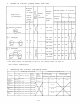
Paging Response Table < When a single exchange is used > No. Department 1st Station No. Last Station No. 1 X PIU-52A Station Paging Zone 01 02 03 04 2 X PIU-52A Function Code 70 05 06 07 08 09 10 11 12 13 14 15 < When the exchanges are connected by tielines > Station Paging Zone Function Code 70 Department type of exchange A 01 02 03 04 09 05 12 06 13 07 14 1st Station No. Last Station No.
Tables for Group Blocking 1 Only when the exchange without tieline. 2 Not used when 2 exchanges are tielined. Activated without No.200 programming.
PART 2. FUNCTION SELECTION FOR DATA TRANSMITTING AND RECEIVING UNITS 8. SETTING CHANNEL SELECT SWITCHES OF TRANSMITTING UNITS (DT-E11) AND WORD SELECT SWITCH OF RECEIVING UNITS (DR-B61) NOTE set the channel select switches located on the printed 1. Connect the DT-E11 and DR-B61 to Exchange correctly. (Refer to installation manuals of DT-E11 and DR-B61.) circuit board, according to the necessary functions such as IN/OUT Annunciation, Calling Party Indication etc, and replace in the Unit. 2.
9 . DIP SWITCH TABLE FOR DATA TRANSMITTING AND RECEIVING UNIT Exchange Data Transmitter Data Receiver – 44 – Relay Output No.
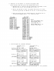
10. System Diagram of Data Transmitting and Receiving Units (When the Exchanges are not connected by means of Tie-line.) Exchange Stations YR-801 YR-802 < Data Receiver (Equipment using DR-B61) > Data Transmitting Unit In/Out Annunciation Display Board YR-803 One-shot-Make Output (50 contacts) Prescription Display Board, etc. Make-Break Output (100 contacts) 8 Selectable Make Output (9 Units) c. Section Chief, a. President. b. Department Chief, d. Chief Clerk Room Condition Indication.
System Diagram of Data Transmitting and Receiving Units – 46 – (When the Exchanges are connected by means of Tie-line.
11. EXPLANATION OF DATA TRANSMITTING UNIT OUTPUT CHANNELS CHANNEL SELECT FUNCTIONS DESCRIPTION APPLICATION Personel in and put registration can be accomplished at any Master sta- CH. 0 IN/OUT Annunciation tion by using personal numbers Max. IN/OUT Annunciation 500 IN/OUT annunciations may be done. One-shot Make Output Make/Break Output 8 Selectable Make Output 50 One-shot make contacts can be ITV camera select available at any Master station.
12. EXPLANATION OF DATA RECEIVING UNIT OUTPUT CHANNELS 12-1 Channel 0 (CH. 0) In/Out Annunciation (Dial Operation) Personal Number Registration Exchange Personal Number Cancellation Data Transmitter Data Receiver Each Relay Output shows last 3 digits (xxx) of Personal Number – 48 – (Relay Make) XXX: 000 ~ 499 (500 contacts) (Relay Break) Relay Output No.
12-2 Channel 1 (CH. 1) (2) Make/Break Output (1) One-shot Make Output (3) 8 Selectable Make Output Exchange Data Transmitter (6) Pager Control Output Relay Output No. Data Receiver CHANNEL SELECT Switch One-shot Make Output One-shot Make Output (5) 4 Decimal digits output (9 unit blocks) (4) Decimal Output (9 unit blocks) 3 Selectable make Output Make/Break Output Make/Break Output 8 Selectable Make Output Unit No. 4 Condition "0" Unit No.
12-3 Channel 2 (CH. 2) Calling Party Indication Lamp Type (1) Each "Calling Station" or "Waiting Station" is shown by Each Indication Lamp. Exchange Data Transmitter Total Number of Stations with Indications : 4 Stations/Channel (8 Stations/2 Channels) Total Number of Calling Stations : Max. 128 Stations/Each Indication Relay Output No. Data Receiver Each Relay Output shows "Calling Station No.
12-4 Channel 3 (CH. 3) Calling Party Indication Exchange Data Transmitter Lamp Type (2) Each "Calling Station" or "Waiting Station" is shown by Each Indication: Lamp. Total Number of Station with Indications : 4 Stations/Channel (8 Stations/2 Channels) Total Number of Calling Stations : Max. 128 Stations/Each Indication Data Receiver Each Relay Output shows "Calling Station No." – 51 – Relay Output No.
TOA ELECTRIC CO., LTD.