INSTALLATION INSTRUCTIONS K3F310 K3F120 K3F220 K3G320 K3G310 K3G220 K3G120 Kontour™ Array Arm Series Spanish Product Description German Product Description Portuguese Product Description Italian Product Description Dutch Product Description French Product Description K3 Series
K3 Series Installation Instructions DISCLAIMER Milestone AV Technologies and its affiliated corporations and subsidiaries (collectively “Milestone”), intend to make this manual accurate and complete. However, Milestone makes no claim that the information contained herein covers all details, conditions or variations, nor does it provide for every possible contingency in connection with the installation or use of this product.
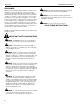
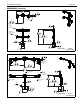
Installation Instructions K3 Series DIMENSIONS K3F120 1.21 30.6 VESA 100 X 100 75 X 75 COMPATIBLE TILT ADJUSTMENT +/-10 DEGREES 39.06 992.2 36.29 921.9 MAX. MONITOR CENTER HEIGHT FROM SURFACE 2.43 61.6 COLUMN WIDTH 0.31 7.9 BASE THICKNESS 18.29 464.7 2.27 57.7 COLUMN DEPTH 3.19 81.0 15.50 393.6 22.68 576.0 DIMENSIONS: K3F220 INCHES [MILLIMETERS] 34.02 864.1 1.60 40.6 15° MAX ANGLE 14.66 372.4 MAX DISTANCE BETWEEN MONITORS 1.21 30.
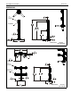
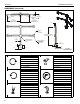
K3 Series Installation Instructions DIMENSIONS (continued) 1.77 45.0 K3F310 15° MAX ANGLE 25.62 650.7 MAX DISTANCE BETWEEN MONITORS 17.71 449.8 MIN DISTANCE BETWEEN MONITORS 55.93 1420.6 2.43 61.6 COLUMN WIDTH 22.68 576.0 DIMENSIONS: VESA 100 X 100 75 X 75 COMPATIBLE 21.12 536.4 1.21 18.54 30.6 470.9 MAX. MONITOR CENTER HEIGHT FROM SURFACE 0.31 7.9 BASE THICKNESS 2.27 57.7 COLUMN DEPTH 15.50 393.6 INCHES [MILLIMETERS] 3.19 81.0 K3G120 1.21 30.6 VESA 100 X 100 75 X 75 COMPATIBLE 38.
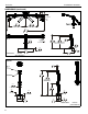
Installation Instructions K3 Series DIMENSIONS (continued) 34.02 864.1 K3G220 1.60 40.6 15° MAX ANGLE 14.66 372.4 MAX DISTANCE BETWEEN MONITORS 1.21 30.6 VESA 100 X 100 75 X 75 COMPATIBLE INTERFACE TILT ADJUSTMENT +/-12 38.81 985.8 36.04 915.3 MAX. MONITOR CENTER HEIGHT FROM SURFACE 2.43 61.6 COLUMN WIDTH 0.25 6.4 BASE THICKNESS 2.27 57.7 COLUMN DEPTH 2.28 57.9 7.03 178.5 7.55 191.8 DIMENSIONS: INCHES [MILLIMETERS] K3G310 1.77 45.0 15° MAX ANGLE 25.62 650.7 MAX.
K3 Series Installation Instructions DIMENSIONS (continued) K3G320 1.77 15° MAX ANGLE 25.62 MAX. DISTANCE BETWEEN MONITORS 17.71 MIN DISTANCE BETWEEN MONITORS VESA 100 X 100 75 X 75 COMPATIBLE INTERFACES 2.43 COLUMN CENTER INTERFACES TILT ADJUSTMENT +/-10 1.21 36.00 MAX MONITOR CENTER HEIGHT FROM SURFACE OUTSIDE INTERFACES 2.27 COLUMN DEPTH .96 7.74 7.11 5.00 2.
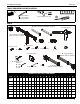
Installation Instructions K3 Series TOOLS REQUIRED FOR INSTALLATION 5/32” (included) 3/16" (included) 5/16" (included) 1/2” (for K3G mounts only) #2 PARTS B - Cable management covers (2 lengths) [Quantities listed as total number of covers] C - Table top base A - Column/array assembly (K3F310 shown as example) D - Column cap E - Base cover H - M4 x 30mm F - 1/4-20 x 1-1/4" K - M4 x 12mm J - M4 x 20mm M - 3/4" L - 3/8" G - Bumper W - Array arm (right) (K3G320 shown as example) P - Grommet pla
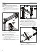
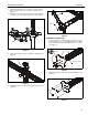
K3 Series Installation Instructions ASSEMBLY Adding Array Arms (K3F220, K3G220 only) (T) 2 NOTE: Be sure the faceplate adjustment knob is on top when installing the arms. (See Figure 1) 1. Slide array arm-right (W) into top of column assembly. (See Figure 1) 2. Tighten two fasteners to secure array arm into place. (See Figure 1) 1 Faceplate adjustment knob (U) (W) (A) (front view) 1 Figure 2 (W) 3. Repeat Steps 1 and 2 for remaining array arms.
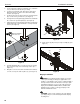
Installation Instructions K3 Series 3. Carefully manipulate base cover (E) to create an opening large enough to wrap cover around array column. (See Figure 4) 4. Wrap base cover around column and slide it down until base cover fits securely onto table top base (C). (See Figure 4) (C) (G) x 6 4 3 Figure 6 K3G Mounts (Grommet) 3 1. (E) Use four 1/4-20 x 1 1/4” flat head cap screws (F) to secure grommet plate (P) to array assembly (A).
K3 Series Installation Instructions 3. Locate a flat surface (thickness minimum of 1" to maximum of 5") on which to mount the array assembly. 4. If a hole doesn’t already exist, drill a hole in desk with a diameter between 1/2" and 3 1/2" at desired mounting location. (See Figure 9) 5. Position mount on desk so that center hole of grommet plate (P) is centered over grommet hole. (See Figure 9) 6. Insert grommet screw (N) through grommet hole and thread into center hole of grommet plate (P).
Installation Instructions K3 Series NOTE: Supplied screws (H, J and K) may not fit properly for all displays. See display’s operating instructions for details. IMPORTANT ! : When applicable, always install center display FIRST in order to prevent stand from tipping! If there are no center faceplates (K3F220 and K3G220), be sure to support opposite arm when mounting displays to prevent stand from tipping! If possible, mount displays to both sides simultaneously.
K3 Series 3. 4. Installation Instructions Using Phillips screwdriver, carefully install two selected screws (J or H) through selected spacers (L or M) into the upper mounting holes on the display. Thread screws completely into display, then back out 3 complete turns. (See Figure 14) 7. Pick up and align display so that screws (K) (installed on the back of the display in the previous step) fit into the mounting holes on the faceplate. Lower the display firmly into place. (See Figure 14) 1.
Installation Instructions 2. K3 Series When arms are at desired pivot position, lock pivot position by tightening pivot adjustment screws using 5/16” hex key (Q). (See Figure 17) Arm Extension (K3G310 and K3G320 only) NOTE: For smaller displays or if converting to a 2x1 array, faceplate assemblies may be removed and reattached to fixed part of the arm. See Faceplate Assembly Removal/Reattachment - Outside Faceplates section for details. pivot adjustment screws 2 1.
K3 Series Installation Instructions Outside Faceplates (K3G310 and K3G320 only) Lateral Shift (On Fixed Arm) 1. Remove hex head bolt from bottom of faceplate assembly. (See Figure 21) NOTE: The procedure below applies when the outside 2. Slide out removable plate from bottom of faceplate assembly. (See Figure 21) faceplates have been attached to the fixed arm. If outside faceplates are still attached to extension arms, use the extension arms for lateral shift. 1.
Installation Instructions K3 Series Center Faceplate(s) (K3G310 shown as example) Pitch 1. Loosen knob on side of center faceplate assembly. (See Figure 25) 2. Adjust pitch as desired. (See Figure 25) 3. Tighten knob to secure desired pitch position. (See Figure 25) 2 1 1 3 1 2 (B) x 3 2 1 2 Figure 26 Figure 25 Roll 1. Loosen screws holding display to faceplate slightly. 2. Adjust roll position as the mounting holes on faceplate allow. 3. Tighten screws to lock roll position.
K3 Series Installation Instructions USA/International Europe Chief, a products division of Milestone AV Technologies 8800-002522 Rev00 2014 Milestone AV Technologies www.chiefmfg.com 01/14 Asia Pacific A P F A P F A 6436 City West Parkway, Eden Prairie, MN 55344 800.582.6480 / 952.225.6000 877.894.6918 / 952.894.6918 Franklinstraat 14, 6003 DK Weert, Netherlands +31 (0) 495 580 852 +31 (0) 495 580 845 Office No.