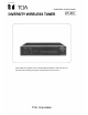
OPERATING INSTRUCTIONS DIVERSITY WIRELESS TUNER WT-870 Please follow the instructions in this manual to obtain the optimum results from this unit. We also recommend that you keep this manual handy for future reference.
GENERAL DESCRIPTION Designed for virtual elimination of problem "null spots" or "dropouts" (momentary loss of radio signal reception), the TOA WT-870 is a diversity tuner that permits simultaneous use of up to two optional wireless tuner modules WTU-870 and WTU-871.
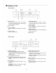
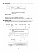
NOMENCLATURE [Front Panel] Power Switch Reception Indicator Press this switch to turn power on. To turn power off, press this switch again. Power Indicator lights when the power is switched on. The left lamp lights when antenna A receives a signal. The right lamp lights when antenna B receives a signal. Power Indicator Level Indicator Tuner Receptacle Lights in proportion to the intensity of input into a wireless microphone. Insert an optional tuner module WTU-870 or WTU- 871.
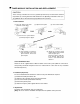
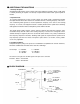
TUNER MODULE INSTALLATION AND REPLACEMENT CAUTION These servicing instructions are for use by qualified personnel only. To avoid electric shock do not perform any servicing other than that contained in the Operating Instructions unless you are qualified to do so. Refer all servicing to qualified service personnel. 1. New Installation (1) Press the stopper of the tuner panel with a screw driver. (3) Open the tuner panel.
OPERATIONS (3) Adjust the volume control of the module of which reception indicator lights. (2) Set the wireless microphone's power switch to ON. The (1) Switch the power on. corresponding module's reception indicator lights. Out The power indicator lights. of two reception indicators for antenna A and B, one corresponding to the antenna receiving the strongest radio signal lights.
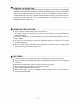
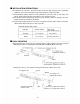
INSTALLATION PRECAUTIONS Install the tuner, antennas, and antenna cable away from high frequency noise generating equipment, such as fluorescent lamps and personal computers, whenever possible. Avoid installing receiving antennas in close proximity to metal stuff, such as steel frames and lockers. Install receiving antennas at least 30cm (1 foot) away from the wall. The distance between two antennas must be over 3m (10 feet).
ADDITIONAL EXPLANATIONS 1. Diversity Reception Conventional single-antenna system receivers have often produced "null spots" where a radio signal is suddenly lost during its reception. The diversity reception method enables stable signal reception all the time. 2. Squelch Circuit In a receiver employing only a noise or carrier squelch, the squelch circuit is actuated and provides the output whenever the receiver receives the same RF carrier as a receiving frequency.
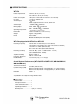
SPECIFICATIONS WT-870 Power Requirements 120V AC, 60 Hz ("L" version) 220~240V AC, 50 Hz ("H" version) Power Consumption DC Input Antenna Input Audio Output Mixing Output Operating Temperature Dimensions Weight Finish 10W (when 2 WTU-870's or WTU-871's are mounted) 12-18V DC, 400mA max. 75 , BNC Power supplied to antenna : 9V DC, 30mA max. –60 dBV, 600 , balanced LINE : 0 dBV, 10k , unbalanced MIC : –60 dBV, 600 , unbalanced –10°C~50°C (14°F~122°F) 210X47.5X280mm (8.3"X1.9"X1.0") Approx. 2.3kg (5.