BreadCrumb® ES1 Version 11 User Guide Model: BreadCrumb ES1 User Guide Version: 11.21 Rev A Firmware Version: 11.21.0 Document Part Number: 03-100158-001 Corporate Headquarters: Rajant Corporation 200 Chesterfield Pkwy Malvern, PA 19355 Tel: (484) 595-0233 Fax: (484) 595-0244 http://www.rajant.
Table of Contents Document Revision History Copyright Statement FCC, CE and Other Certification Statements Antennas Safety Modifications Professional Installation Attestation Maximum Certified Power GNU General Public License Statement Preface 1. Introduction to BreadCrumbs 1.1 What is a BreadCrumb? 1.2 The Mesh Network 2. Description of a BreadCrumb ES1 2.1 Radios 2.2 Enclosure 2.3 Antenna Connectors 2.4 Power and Ethernet 2.5 M8 Connector 2.6 Status LED 2.
D.7 Connecting Power D.8 Configuration D.9 Placement Appendix E: Sealed RJ45 Assembly E.1 Parts of the Male Sealed RJ45 Ethernet Connector E.2 Choose the Correct Soft Plug E.3 Pre-thread Before Termination E.4 Terminate Cable with the Metal-Shielded RJ45 Plug E.5 Test the Ethernet Cable E.6 Preparation After Termination E.7 Mate Inner and Outer Shells E.8 Connect RJ45 to Female WAPV RJ45 E.9 Mate and Then Cap the WAPV Appendix F: Mounting Instructions F.1 Pole Mounting Bracket F.
Document Revision History Revision Date Changes 11.
Copyright Statement Rajant, the Rajant logo, BreadCrumb, InstaMesh, BC|Commander, and Bring Your Network with You! are registered trademarks of Rajant Corp. in the United States and certain other countries. Rajant’s patented InstaMesh® networking software enables the network to quickly adapt to rapidlydeployed and moving network elements. U.S. Patents 9,001,645, US 9,001,645 B2, US 9,319,922 B2 and US 9,979,635 B2. BreadCrumb® ES1 Version 11 User Guide Copyright © 2009–2019 Rajant Corp. All rights reserved.
FCC, CE and Other Certification Statements FCC ID ( VJA-ES12450R): This equipment has been tested and found to comply with the limits for a Class A digital device, pursuant to Part 15 of the FCC Rules. These limits are designed to provide reasonable protection against harmful interference when the device is operated in a commercial environment.
Required Antenna Separation The antennas from any transceiver of the BreadCrumb ES1 may not be co-located with the antennas of any other transceiver. The co-location restriction is satisfied by maintaining 20 cm separation between the antennas of different tranceivers. There is no restriction for the separation between the antennas from the same transceiver, but testing at installation is recommended to verify the system performance that is achieved with a specific antenna deployment.
ground connections must be used and must be connected to a protective earth ground. Protective earth grounding operations must be performed by trained personnel, and according to local electrical codes and industry best practices, as well as Rajant’s own recommendations. Modifications CAUTION Changes or modifications not expressly approved by Rajant Corp. could void the user’s authority to operate the equipment.
Table: Maximum Certified Power: CE (Austria, Belgium, Bulgaria, Croatia, Cyprus, Czech Republic, Denmark, Estonia, Finland, France, Germany, Greece, Hungary, Iceland, Ireland, Italy, Latvia, Liechtenstein, Lithuania, Luxembourg, Malta, Netherlands, Norway, Poland, Portugal, Romania, Slovakia, Slovenia, Spain, Sweden, Switzerland, Turkey, United Kingdom) IMPORTANT: Regarding indoor-only frequencies In regions where radio frequencies are regulated by ETSI (CE), the frequency range 5170-5350 MHz is restricted
GNU General Public License Statement Certain components of the Rajant BreadCrumb firmware are subject to the GNU General Public License Version 2, or other so-called open source licenses (“Open Source Software”).
Preface Purpose and Scope This manual provides information and guidance to all personnel who are involved with and use Rajant Corporation’s BreadCrumb ES1. This manual begins with an introduction to the BreadCrumb Kinetic Mesh Network. It then characterizes the features of the BreadCrumb ES1. Finally, it describes common deployment scenarios and provides concise step-by-step instructions for each scenario.
Features LX5 ME4/KM3 ES1 JR2 JR3 SlipStream Input Voltage 18-48 VDC 8-48 VDC (ME4)/20-48 VDC (KM3) 9-30 VDC 8-30 VDC 9-30 VDC 12 VDC Min.
1. Introduction to BreadCrumbs Rajant Corporation’s ( http://www.rajant.com) BreadCrumbs utilize the 802.11 wireless networking standards to form a wireless mesh network. The network is mobile, self-integrating, self-meshing, selfhealing, and secure. The focus is on flexibility, adaptability, and simplicity. The BreadCrumb Kinetic Mesh Network is intended for rapid deployment of a broadband wireless network into a situation or “hot zone.
The intelligence of a BreadCrumb network is in how it adapts rapidly to the creation or destruction of the links in the mesh as devices are moved, switched OFF or ON, blocked by obstructions, interfered with by other devices, or otherwise affected. This adaptation takes place automatically and immediately as needed. 1.2.2 BreadCrumb Mesh Connections In order for two BreadCrumbs to establish a mesh link to each other, they must be set to the same radio channel and have the same Network ID.
2. Description of a BreadCrumb ES1 BreadCrumb ES1 is a portable, wireless device for use in indoor, protected and outdoor locations. It is light in weight, supports up to 4 external antennas and is designed to be completely mobile. The BreadCrumb ES1 must be powered by an external passive PoE (Power Over Ethernet) source. 2.1 Radios The BreadCrumb ES1 contains two radios. There are different models of ES1, each with a different combination of radios.
2.2.2 Enclosure Front The external features of the ES1 enclosure are shown in the following images. The following figure shows a four-antenna ES1 model. A model that needs only three antennas will have three antenna connectors instead of four.
(1) Up to four type N female antenna connectors (2) Two flip-open accesses to mounting holes (3) Protective vent (4) ETH0 RJ45 female, receives power via Ethernet Passive PoE (5) 5-pin female M8 connector for USB (and optionally reset) adapter cables (6) Status LED 2.2.3 Enclosure Bottom The bottom of the BreadCrumb ES1 enclosure contains most of the features.
Because the BreadCrumb ES1 case is plastic, antennas should not be direct attached and should be attached only using antenna cables. This is to avoid stressing the plastic and compromising the IP67 ingress rating. Low loss cable such as LMR-400 is recommended for externally attached antennas. Warning For all BreadCrumb models, for installations that will experience vibration or shock, all antennas should be externally mounted and attached using cables.
electrostatic discharge, and electrical fast transient/burst immunity compliant to the IEC 61000-4-2, and IEC 61000-4-4-EFT standards, respectively. For more information on the BreadCrumb ES1 sealed Ethernet connector, see Ethernet Connector. 2.4.1 Power Requirements The BreadCrumb ES1 ETH0 port supports Passive Power over Ethernet (Passive PoE), and therefore acts as a dual function Ethernet and DC power input port for the BreadCrumb ES1.
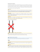
Additional information about Rajant power supply accessories can be found in the Power Accessories product spec sheet at www.rajant.com. 2.4.2 PoE Power Supply Usage The laptop in these diagrams could instead be a non-PoE switch port connecting the BreadCrumb to a LAN. Figure: BreadCrumb ES1 Ethernet and Passive PoE AC Connections Figure: BreadCrumb ES1 Ethernet and Passive PoE DC Connections Proper Use of PoE Power Supply 1. 2. 3. 4.
Please note that Rajant warranty protection does not cover any damage caused by misuse of power supplies or by use of third-party power supplies. Warning In order to avoid sparking and possible damage to the unit, connect the powered Ethernet Output cable to the BreadCrumb before applying power to the power supply.
Do not lose the M8 plastic screw-in protective cap. The ES1 M8 connector is only protected from water if the protective cap is screwed in or if a Rajant ES1 M8 adapter cable is properly installed. The protective cap is Finecables Enterprise Co. Ltd. part number PCNM8x1.0-2. A custom ES1 M8 male to USB 2.0 female adapter cable (shown below) provides a female USB A 2.0 port (Rajant p/n 06-100069-001). Figure: ES1 M8 Male to USB 2.
Rajant ES1 M8 adapter cables use a connector similar to this molded straight shielded 5-pin male connector from Finecables Enterprise Co. Ltd., for example MA08MSBF05STXXYB25, where XX is cable length and Y is “C” for PVC or “R” for PUR cable jacket. 2.5.2 Connecting ES1 M8 Adapter Cable Use the following steps to connect an ES1 M8 adapter cable: • Turn off power to the BreadCrumb ES1’s power supply. • It is difficult to visually line up the M8 keys, so instead do it by feel.
Figure and Table: BreadCrumb ES1 M8 5-pin Female Pinout Pin Signal 1 USB 5 V + 2 USB DATA - 3 GND 4 USB DATA + 5 Reset Switch 2.5.4 USB The BreadCrumb ES1 contains one USB 2.0 interface on the pins of its 5-pin M8 connector. The port is compliant to the Enhanced Host Controller Interface (EHCI) and USB Transceiver 2.0 Macrocell Interface (UTMI+) Level 2 specifications. The port supports all three standard data transfer rates of low speed (1.5Mbps), full speed (12Mbps), and high speed (480Mbps).
Color Status Blinking Green At least one connected Mesh peer; all peers are connected at less than 24 Mbps Solid Green At least one connected Mesh peer; one or more peers are connected at 24 Mbps or faster Blinking Yellow (with short and long pauses between blinks) Numeric warning code Blinking Red (with short and long pauses between blinks) Numeric error code Blinking Yellow (blinking at an increasing rate) BreadCrumb is in the process of installing firmware All LED colors scrolling in rapid su
Configured State Alternate State On Off Off N/A Alerts Only On Off (switchable) On Note that state changes can occur only between options in the same rows of the table above. For example, it is possible to toggle the state back and forth between Alerts Only and On, but not between Alerts Only and Off. Transitioning from Alerts Only to Off would require changing the LED mode setting in BC|Commander. The default LED Mode for the BreadCrumb ES1 is On.
3. Using BC|Commander BC|Commander is Rajant’s BreadCrumb administration software package used for monitoring the status of BreadCrumbs and mesh links. BC|Commander is also used for configuring BreadCrumbs, upgrading BreadCrumb firmware, and graphically displaying the network topology. BC|Commander can be run on any computer that has access to the BreadCrumb network. Versions of the software package are available for Microsoft Windows® or Linux. BC|Commander includes an option called v10 Compatibility Mode.
4. Deploying a BreadCrumb Mesh Network There are many factors which need to be taken into account when deploying a BreadCrumb mesh network. This chapter describes the addressing scheme of the mesh, channel assignments and some of the most commonly occurring environmental factors that will have a major impact on the performance of the mesh. The final section details guidelines and methodology needed to follow when deploying the mesh.
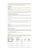
Radio Card Frequency and Type Default Channel Second Default 4.9 GHz 802.11a 20 5 GHz 802.11a 153 161 5 GHz 802.11n FCC:157, CE:136 FCC:149, CE:100 Dual band 2.4/5 GHz 802.11n 11 (2.4 GHz) Third Default In some cases, it may be necessary to manually set the radios to specific channels to provide critical links within a mesh. This can be especially important when using single-radio BreadCrumb devices.
Antenna Tuning BC|Commander version 11.9 and higher, when viewing the Live Mesh, has the ability to monitor the quality of a single wireless connection between two BreadCrumbs for the purpose of antenna tuning aka antenna peaking. The “Antenna Tune” option is available from the context menu in the Peer table. Before attempting antenna tuning, verify that BC|Commander is viewing the Live Mesh.
The BreadCrumbs being monitored will be instructed to send BC|Commander wireless connection information at 1 second intervals (regardless of the BreadCrumb configuration setting BCAPI: General Update Interval). These accelerated updates will continue until the Antenna Tuning dialog is closed. If either BreadCrumb were to lose the connection to its peer, graphing will flatline or pause until the connection is restored.
• Other BreadCrumb devices that are placed too closely together. • Other RF devices such as microwave devices, cordless phone base stations, radio transmitters, other wireless networks, jamming devices, etc. • Metal surfaces such as fences and building can cause radio waves to be reflected, causing multipath interference. Caution Plan the BreadCrumb Wireless Network to minimize the effects of RF interference. 4.3.
b. Note any LOS obstructions, and plan BreadCrumb placement to work around them. 2. Identify the PC on which BC|Commander will be run. a. This PC should have a wireless NIC, as you will need to carry it with you as you deploy the mesh. b. Alternatively, the BC|Commander PC can be stationary with one person monitoring BC|Commander while another deploys the BreadCrumbs. This method requires some form of communication (radio, cell phone, etc.) between the two persons. 3.
5. Firmware Upgrade and Zeroize Each BreadCrumb relies on low-level software known as firmware for proper execution. For a BreadCrumb to communicate with other BreadCrumb devices or a BC|Commander client, the firmware version of the device must be compatible with the firmware versions of all other devices within the network, and with the version of BC|Commander running on the client computer.
connected, turn power to the BreadCrumb OFF and then ON again. Observe the Status LED to monitor progress. If, during this second firmware upgrade attempt, another error occurs, take note of the new error code and then apply for technical support. 4. When complete, turn power to the BreadCrumb OFF, disconnect the USB storage device, then turn power to the BreadCrumb back ON. 5.2 Zeroize CAUTION Do NOT turn off or reboot a BreadCrumb while it is being zeroized.
6. Troubleshooting Note Battery tips apply to any BreadCrumb that is powered by batteries, solar power or any power source that may become irregular or weak. DFS and Troubleshooting When troubleshooting problems with a BreadCrumb radio on a 5 GHz DFS channel, remember that radio must listen for radar and not transmit (or mesh) for typically 1 minute after is it fully booted. Channels in the frequencies 5600-5650 MHz, if available, may have a 10 minute wait.
c. When using external antennas, faulty cable connections or crimped cables can result in difficulty establishing and maintaining network connectivity. ◦ Check antenna cables and their connections to the BreadCrumb device. 6.3 BreadCrumb Power and Start-Up Issues a. Discharged external batteries can cause a BreadCrumb to appear to power up(“PWR” LED is lit), but fail to start-up. ◦ Monitor battery usage and charge/replace batteries as necessary. b.
7.
Appendix A: Radio Channels and Frequencies Rajant BreadCrumbs contain from one to four radios, depending on the model. 802.11g radios are used in the 900 MHz and 2.4 GHz bands. 802.11a radios are used in the 4.8 GHz, 4.9 GHz and 5 GHz bands. 802.11n radios are used in the 2.4 GHz and 5 GHz bands. Each BreadCrumb model supports its own specified radio or combinations of radios. The radios support the channels and frequencies listed in the following tables.
quency than) the first 20 MHz while minus (-) indicates that the additional 20 MHz occurs below (at a lower frequency than) the first 20 MHz. Note Note, the frequency noted is the center frequency of the base 20 MHz channel. HT40 operation (+ or -) is compatible with 802.11b and 802.11g 20 MHz, and 802.11n HT20 modes. A.2 Radio: 5 GHz 802.11n Table: 5 GHz 802.
(5680 MHz) and HT40-, and if a second radio is present, its default channel and mode is 100 (5500 MHz) and HT40+. In other countries the default channels may differ based on local regulations. Note If the default channels aren’t available, the default will instead be the first valid channel (in order of channel number) with the largest bandwidth (up to 20 MHz) that doesn’t conflict with other radios. If that fails, meshing will be disabled on that radio. Some 5 GHz channels support HT40 mode.
1 minute completes without detecting radar, the radio can then start normal operation on the channel while still continuously checking for radar. Note: Channels from 5600 MHz to 5650 MHz, if available, may have a 10 minute CAC period. • If radar detection is triggered on a DFS channel, that radio will stop transmitting for 30 minutes (the Non-Occupancy period aka NOP).
Appendix B: Error and Warning Codes Possible BreadCrumb error and warning codes are listed below. A BreadCrumb can have multiple errors or warnings listed in the Alerts tab of BC|Commander but only one code will be flashed on the BreadCrumb’s status LED. A few codes such as 811 and 335 are non-flashing alerts. For a BreadCrumb with other active alerts, the lowest number error code will flash on the BreadCrumb’s status LED, and if there are no errors then the lowest number warning will flash.
Code Firmware Upgrade Codes (1*) 127 Failed to copy file system image. 128 Failed to checksum file system image. 129 Failed to create directory for next file system image. 131 Failed to mount next file system image. 132 Failed to create directory for settings. 133 Failed to copy current settings to next file system image. 134 Failed to unmount next file system image. 135 Failed to copy init image. 136 Failed to copy bootloader image.
Code Firmware Upgrade Codes (1*) 25 Internal developer overrides detected. Code Self-Test Codes (3*) 31 Hardware configuration not set. Factory initialization required. 311 Hardware error detected. 32 BreadCrumb has been zeroized. 321 BreadCrumb is being zeroized. 322 Breadcrumb is in Deployment Mode. 33 Radio(s) not detected. 331 Radio in MANUAL compliance mode is violating country regulation. 332 Spectrum Access not granted 333 Low Battery 334 Gas gauge not initialized.
Code Firmware Upgrade Codes (1*) 418 Flash image may not be installed while in FIPS mode. 42 Mixed SecNet/Non-SecNet configuration. 421 Default password in use 43 Rekeying error. 44 Rekeying error. 45 Rekeying error. 46 Rekeying error. 47 Rekeying error. 48 Rekeying error. 49 Rekeying error. 431 Rekeying error. 432 Rekeying error. 433 Rekeying error. 434 Rekeying error. 435 Rekeying error. 436 Rekeying error.
Code Firmware Upgrade Codes (1*) 66 Incorrect ME3 gas gauge revision 0 EEPROM settings. 67 Internal battery charger disabled. Code Other Codes (7, 8, 9*) 71 Host flapping detected. 72 Critical I2C failure. 73 Invalid channel configured. 74 Bad v10 factory configuration. 741 Signing key installation failure. 75 Unsupported hardware component. 76 Potential loop detected, turned off port 77 Model is not supported in this version of firmware. Contact support.
Appendix C: Ports and Protocols Table: Ports and Protocols Service From To Protocol BreadCrumb Discovery Ephemeral port on BC|Commander workstation 224.0.0.
Service From To Protocol BreadCrumb IPv4 or IPv6 address, ephemeral port tener, ephemeral port for data flow TRoIP Audio RTP Traffic BreadCrumb IPv4 address, ephemeral port IPv4 multicast address 225.0.0.1-225.0.2.
Appendix D: Installation Guidelines Guidelines follow for installing a typical Rajant BreadCrumb. The order of installation may differ depending on where the BreadCrumb will be installed and configured. Also read all warnings and guidance in the rest of this guide. D.1 Professional Installation Is Required Model: BreadCrumb ES1 Professional installation is required for this device and will be performed only by someone knowledgeable of its use.
antennas. There is no restriction for the separation between the antennas from the same transceiver, but testing at installation is recommended to verify the system performance that is achieved with a specific antenna deployment configuration. Warning For installations that will experience vibration or shock, all antennas should be externally mounted and attached to the ES1 using cables. Low loss RF cable such as LMR-400 is recommended for cable attached antennas.
To protect the user against the risk of electric shock during high voltage transient events which may occur when this equipment is installed outdoors, protective earth grounding of the POE power supply is required. Case ground connections are provided on all Rajant supplied POE power supplies. The case ground connections must be used and must be connected to a protective earth ground.
Appendix E: Sealed RJ45 Assembly Important Installing the WAPV male sealed RJ45 connector requires proper tools and expertise in building shielded CAT5e / CAT6 network cables. Warning While the sealed RJ45 is being built there should be NO POWER attached to the cable. The male sealed RJ45 connector is a Genesis Technology WAPV-100-AKY0T which includes soft plugs to fit two different ranges of cable diameter. This section will refer to the connector as just “WAPV”. E.
E.2 Choose the Correct Soft Plug Only one soft plug is used when building the connector. Measure the diameter of your Ethernet cable and choose the one that is correct for that diameter. This is important for getting a sealed connection. • Red plug is for cable 7.0 - 8.1 mm diameter. • Black plug is for cable 5.0 - 6.0 mm diameter Figure: Red or Black WAPV Soft Plug Choice E.
E.4 Terminate Cable with the Metal-Shielded RJ45 Plug Important This step should be performed by someone with the proper tools and expertise in building CAT5e / CAT6 network cables. Expose the eight insulated wires and the drain or braid of the unterminated end of the Ethernet cable and then install the metal-shielded male RJ45 plug. This requires proper tools and expertise in building shielded network cables.
be threaded over the RJ45 plug. Note that this end has the smaller key blocks and the narrow shelf where the soft circular washer will rest.
Inside the outer shell (where it faces the inner shell) are the small square keys (block-like bumps). Line up those keys with the recessed channels on two sides of the inner shell. Then hold the inner shell (1) and press the outer shell (2) onto the inner shell. Use some pressure to get around the tight corner of the channel, then rotate the outer shell in the direction shown by the yellow arrow below. Once mated, the outer shell should be loosely trapped over the inner shell.
(2) Male metal-shielded RJ45 plug (arrow pointing at the plastic latching tab) (3) Combined male WAPV inner and outer shell w/ soft plug and soft circular washer (4) Cap Note the location of the RJ45 plug’s plastic latching tab, pointed at by arrow (2) in the photo above. E.9 Mate and Then Cap the WAPV Look inside the end of the combined male WAPV shell that faces the RJ45 plug. You should be able to see the soft circular washer laying flat, and directly beneath that see the RJ45-shaped (keystone-shaped).
(1) Combined male WAPV inner and outer shell w/ soft plug (and soft circular washer is inside) (2) Cap Figure: Fully Mated WAPV Connection Note Even though these parts should form a sealed connection, Rajant recommends taping all outdoor connections. For general information on taping connections, see the documents Waterproofing Rajant BreadCrumb RF Connections and Waterproofing Rajant BreadCrumb RF Connections in the Technical Bulletins appendix of this guide.
Appendix F: Mounting Instructions The BreadCrumb ES1 has two mounting holes which are found on the center left and right of the front and back of the ES1. The mounting holes are 131 mm (5.15 inches) apart (center to center) and are intended for M4 machine screws with washers to distribute the pressure on the plastic. The two mounting holes are accessed from the front of the BreadCrumb ES1 via small flip-up access compartments on the left and right front border of the ES1.
one slot and up through the matching slot of the pair). A hose clamp for a wider diameter pole should be threaded only through the outer pair of slots. Hose clamps ½ to ¾ inch wide may be used. It may be easier to thread the hose clamp before attaching the pole mounting bracket to the BreadCrumb ES1. Continue for the correct use of washers and nut when attaching the pole mounting bracket.
F.2 DIN Rail Mounting Bracket The DIN rail mounting bracket for BreadCrumb ES1 attaches to the back of the ES1 as described below. This bracket assembly can be attached to a 35 mm top hat DIN rail. The following diagrams show a BreadCrumb ES1 with DIN rail mounting bracket attached. In these diagrams, the DIN rail mounting bracket is attached so the DIN rail clip will be over the left side of the ES1 (the side with the protective vent).
Note The proper orientation for the DIN rail clip is with the fixed (non spring-loaded) end up, and the springloaded end of the DIN rail clip at the bottom. This insures that the fixed end of the clip will bear the weight. The Ethernet port, M8 port and status LED are on the bottom side of the BreadCrumb ES1.
The BreadCrumb ES1 may now be attached to a 35 mm top hat DIN rail.
Appendix G: Technical Bulletins G.1 Rajant Best Practices: Grounding and Surge Protection July 11, 2018 Copyright © 2018, Rajant Corporation. All rights reserved. G.1.1 Introduction The Rajant BreadCrumb product line is designed to withstand the toughest conditions imposed by military and industrial scenarios.
We continue to elaborate on these recommendations in the following sections. G.1.4 Ethernet Surge Protection An Ethernet cable provides a path for a power surge to enter a BreadCrumb. The longer the cable, the more susceptible it is to picking up surges. In case of a lightning strike, the cable will act as an antenna and absorb the electro-magnetic wave caused by the strike even from a long distance. Surges through the Ethernet port can be suppressed by an Ethernet surge protector.
• Tested and fully compatible with Rajant BreadCrumb ME3, ME4, and LX4 devices. Installing the Ethernet Surge Protector The Ethernet surge protector should be installed as close to the BreadCrumb as practical, and ideally within 50 cm (20 in) of the device. The surge protector should be grounded as described in its operating manual, and according to local electrical codes and industry best practices. When a BreadCrumb is powered through its Ethernet port (i.e.
G.
G.3 Waterproofing BreadCrumb Cable Connections Rajant Technical Service Bulletin: Instructions to properly seal Squid cables Issue: For BreadCrumb products deployed in outdoor installations, it is recommended to waterproof all Squid cable connections to the BreadCrumb to prevent any liquid from seeping into the connectors.
Items needed: Self fusing weather proofing tape http://www.amazon.
Star Brite Liquid Electric tape (do not use Gardner Bender brand Liquid tape.) http://www.amazon.com/Star-brite-84134-Liquid-Electrical/dp/B000Y82XVC/ Di‐Electric Grease Use the Di‐Electric Grease shown above to fill any gaps in the threads of the connectors. http://www.amazon.
Solution: Properly apply Di‐Electric Grease, Fusing Silicone weatherproofing tape and Starbrite liquid electric tape to “weather proof” the connectors. Below are instructions on how to seal both the Amphenol and LTW connectors to prevent any fluid seepage. NOTE: A BreadCrumb LX4 is used for the photos. Apply a small strip to the female threads of Eth connectors, USB port and the outside of the female Amphenol connector. The brand of Di‐Electric grease is unimportant. However a gel type is preferred.
Make the connections ensuring that the connectors are secure but not over tightened which may cause cross threading on the LTW connectors. Ensure that the Amphenol connector is properly locked into place. Wrap the Amphenol connector with Fusing Silicone weatherproofing tape starting at the bottom and wrapping upward so that overlaps are at the bottom. Stop at the top of the connector as shown below.
Add a thin layer of Liquid electrical tape to the top of the connector overlapping the self fusing silicone tape to seal the top of the connector as seen above. Next connect the LTW connector on the Eth0 port and replace the caps on the Eth1 and USB ports. If the Eth 1 or the USB port is going to be used connect the LTW side of the cable to the squid. Apply a thin layer of Star Brite Liquid tape.
The Liquid Electric tape should remain pliable so it can be removed to service the radio. Do not use Gardner Bender brand Liquid tape. This brand tends to become very hard over long periods of time which may impair removal. Additional Notes: When installing the BreadCrumb, the Squid cable should be secured but hang down. Bending the Squid cable up may compromise the integrity of the adhesive in the heatshrink allowing liquid to build up and possibly flow into the cable.
Some Cisco switches support both IEEE 802.3af/at PoE or their own proprietary version. Their default mode is called “auto”. In “auto” mode, the switch will try to automatically detect what type of PoE the plugged in device supports. The Cisco switch auto method does not work with passive PoE equipment including plugging into the data input ports of Rajant PoE devices that are used with the ME4, LX5, and JR2. The link will not come up or will “flicker” up and down.
2. Using two data cables, connect both the data INPUT and data plus POE OUTPUT port of the Rajant POE to an unmanaged switch. 3. Confirm that a data link is formed by inspecting the link lights on the Ethernet switch ports. 4. If the POE does not form a data link on both ports of the Ethernet data switch, replace the POE with a new one. Mitigation: The recommended best practice is to only connect the Rajant POE IN port to a non-POE Ethernet switch.
Appendix H: Rajant End User License Agreement IMPORTANT: PLEASE READ THIS END USER LICENSE AGREEMENT CAREFULLY. IT IS ENCLOSED IN THE SOFTWARE PACKAGE AND /OR PRESENTED ELECTRONICALLY WHEN ACCESSING THE SOFTWARE. BY CLICKING “I AGREE”, YOU ARE AGREEING TO BE BOUND BY THE TERMS OF THIS LICENSE.
and register Customer’s copy of the Software online at RAJANT’S website to obtain the necessary license key or license file.
USER PURCHASER OR LESSEE OR OTHERWISE HOLDS A VALID LICENSE TO USE THE SOFTWARE WHICH IS BEING UPGRADED; AND (3) THE MAKING AND USE OF ADDITIONAL COPIES IS LIMITED TO NECESSARY BACKUP PURPOSES ONLY. Proprietary Notices. Customer agrees to maintain and reproduce all copyright, proprietary, and other notices on all copies, in any form, of the Software and Documentation in the same form and manner that such copyright and other proprietary notices are included on the Software.
Subject to the limitations and conditions set forth herein, RAJANT warrants that commencing from the date of shipment to Customer (but in case of resale by an Approved Source other than RAJANT, commencing not more than ninety (90) days after original shipment by RAJANT), and continuing for a period of the longer of (a) ninety (90) days or (b) the warranty period (if any) expressly set forth as applicable specifically to software in the warranty card accompanying the product of which the Software is a part (
Unless otherwise listed on this Warranty Schedule, Rajant warrants to the purchaser that the Products will perform in all material respects in accordance with their written specifications for a period of ninety (90) days from the date of purchase.
LIMITATION OF LIABILITY FOR SOFTWARE IS CUMULATIVE AND NOT PER INCIDENT (I.E. THE EXISTENCE OF TWO OR MORE CLAIMS WILL NOT ENLARGE THIS LIMIT).
Controlling Law, Jurisdiction. Customer agrees that all sales occurred, and contracts entered into at Malvern, Pennsylvania, notwithstanding the location of any affiliate or Customer’s location or principal place of business.
Appendix I: GNU General Public License Version 2, June 1991 Copyright © 1989, 1991 Free Software Foundation, Inc. 59 Temple Place, Suite 330, Boston, MA 021111307 USA Everyone is permitted to copy and distribute verbatim copies of this license document, but changing it is not allowed. PREAMBLE The licenses for most software are designed to take away your freedom to share and change it.
ered only if its contents constitute a work based on the Program (independent of having been made by running the Program). Whether that is true depends on what the Program does. 1.
c) Accompany it with the information you received as to the offer to distribute corresponding source code. (This alternative is allowed only for noncommercial distribution and only if you received the program in object code or executable form with such an offer, in accord with Subsection b above.) The source code for a work means the preferred form of the work for making modifications to it.
tion is permitted only in or among countries not thus excluded. In such case, this License incorporates the limitation as if written in the body of this License. 2. The Free Software Foundation may publish revised and/or new versions of the General Public License from time to time. Such new versions will be similar in spirit to the present version, but may differ in detail to address new problems or concerns. Each version is given a distinguishing version number.
Also add information on how to contact you by electronic and paper mail. If the program is interactive, make it output a short notice like this when it starts in an interactive mode: Gnomovision version 69, Copyright © year name of author Gnomovision comes with ABSOLUTELY NO WARRANTY; for details type ‘show w’. This is free software, and you are welcome to redistribute it under certain conditions; type ‘show c’ for details.