
User's Guide

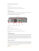

(1) Up to four type N female antenna connectors
(2) Two flip-open accesses to mounting holes
(3) Protective vent
(4) ETH0 RJ45 female, receives power via Ethernet Passive PoE
(5) 5-pin female M8 connector for USB (and optionally reset) adapter cables
(6) Status LED
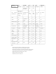
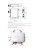
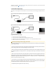
2.2.3 Enclosure Bottom
The bottom of the BreadCrumb ES1 enclosure contains most of the features.
Figure: BreadCrumb ES1 Enclosure Features (Bottom)
(1) Two (of up to four) type N female antenna connectors
(2) Protective vent
(3) Built-in half of sealed Ethernet connector
(4) ETH0 RJ45 female, receives power via Ethernet Passive PoE
(5) 5-pin female M8 connector for USB (and optionally reset) adapter cables
(6) Status LED
2.3 Antenna Connectors
The BreadCrumb ES1 provides up to four Type N female antenna connectors. Two antenna connectors
are located on the top of the enclosure and two on the bottom of the enclosure (see the Enclosure Fea-
tures (Front) figure above). Many BreadCrumb radios offer antenna diversity or Multiple-Input and Multi-
ple-Output (MIMO) features, in which case two antenna ports per radio are utilized. Some radios only uti-
lize one antenna port. Each antenna connector will be labeled with a unique letter (A, B, C or D) and the
frequency of its corresponding radio.
Required Antenna Separation
The antennas from any transceiver of the BreadCrumb ES1 may not be co-located with the antennas of
any other transceiver. The co-location restriction is satisfied by maintaining 20 cm separation between
the antennas of different tranceivers. There is no restriction for the separation between the antennas
from the same transceiver, but testing at installation is recommended to verify the system performance
that is achieved with a specific antenna deployment.
Warning
Warning