
User's Guide
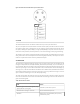
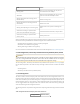


Color Status
Blinking Green
At least one connected Mesh peer; all peers are
connected at less than 24 Mbps
Solid Green
At least one connected Mesh peer; one or more
peers are connected at 24 Mbps or faster
Blinking Yellow (with short and long pauses
between blinks)
Numeric warning code
Blinking Red (with short and long pauses be-
tween blinks)
Numeric error code
Blinking Yellow (blinking at an increasing rate)
BreadCrumb is in the process of installing firm-
ware
All LED colors scrolling in rapid succession
(with a short pause between every cycle)
Successful firmware installation; ready to reboot
All LED colors scrolling in rapid succession
(with no pause)
Identify mode is ON
Note: If the BreadCrumb configuration setting InstaMesh.. Advanced.. Enable Live Trace to Gateway is set,
then the connectivity-related behavior of the blue and green LEDs is modified as follows:
• Solid Blue: No path to gateway, or there is no gateway configured
• Solid Green: Low InstaMesh cost to gateway
• Blinking Green: High InstaMesh cost to gateway
For more information on BreadCrumb Status LED numeric codes see Appendix Error and Warning Codes.
2.7 LED Configuration / Zeroize Keys and Restore Factory Defaults (Reset) Switch
Important
Important
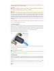
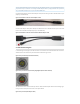
The BreadCrumb ES1 Zeroize aka Reset switch is available via a Rajant adapter cable for the ES1 M8
The BreadCrumb ES1 Zeroize aka Reset switch is available via a Rajant adapter cable for the ES1 M8
port. On a running BreadCrumb, the features of this switch are also available over the air using the
port. On a running BreadCrumb, the features of this switch are also available over the air using the
BC|Commander application BreadCrumb menu and BreadCrumb configuration settings.
BC|Commander application BreadCrumb menu and BreadCrumb configuration settings.
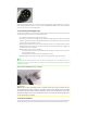
The LED Configuration / Zeroize Keys and Restore Factory Defaults Switch (see the Enclosure Right figure)
has two modes of operation. The modes are set by the length of time the switch is asserted. The modes
are:
• LED Configuration
• Zeroize Keys and Restore Factory Defaults (Reset)
2.7.1 LED Configuration
This mode is used to control the display states of the Status LED. The LED Configuration function is ac-
cessed by pressing the switch and releasing it after a two second hold. The configured display state of the
Status LED is dictated by the LED Mode setting that is configured from BC|Commander (please refer to
the BC|Commander Version 11 User Guide for a more detailed description of the LED Mode setting). The
user can toggle between the configured state and an alternate state of the Status LED by pressing the
switch and activating the LED Configuration function.
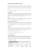
The following table lists the possible configured and corresponding alternate display states of the Status
LED.
Table: Configured and Alternate Display States of the Status LED
Configured State Alternate State