
User's Guide
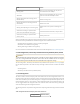


Radio Card Frequency and Type Default Channel Second Default Third Default
4.9 GHz 802.11a 20
5 GHz 802.11a 153 161
5 GHz 802.11n FCC:157, CE:136 FCC:149, CE:100
Dual band 2.4/5 GHz 802.11n 11 (2.4 GHz)
In some cases, it may be necessary to manually set the radios to specific channels to provide critical links
within a mesh. This can be especially important when using single-radio BreadCrumb devices. Refer to
the BC|Commander Version 11 User Guide for the details of BreadCrumb channel configuration.
4.3 Physical Placement and other Considerations
Commonly occurring environmental factors have a significant impact on performance and behavior of
the BreadCrumb Wireless Network. Line-of-sight (LOS) obstructions, distance, weather, and device place-
ment should all be considered when deploying a wireless network.
IEEE 802.11 wireless operation degrades gradually as distance increases between nodes or as interfer-
ence becomes prominent. This manifests as a data rate reduction between nodes.
The goal in planning and deploying a BreadCrumb mesh network is to maximize both coverage and the
data transfer rate between devices. These can be maximized by taking into consideration all of the con-
tributing factors described in this section.
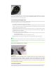
4.3.1 Line-of-Sight
Unobstructed line-of-sight (LOS) is critical for optimal performance of the mesh. Partial LOS obstruction
results in noticeable network performance degradation. Total LOS obstruction can result in complete
loss of network connectivity.
Elevating the device and external antenna will assist in providing better LOS. This can allow the radio
waves to propagate over some possible obstructions.
Unobstructed LOS is not necessary from every BreadCrumb device and wireless client to every other
BreadCrumb device and wireless client. However, each device must have unobstructed LOS to the previ-
ous and subsequent device.
Client connectivity will degrade and drop if LOS to a BreadCrumb device can not be maintained.
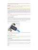
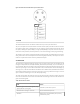
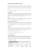
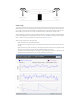
Fresnel Radius
The Fresnel Radius column in the Peers tab of BC|Commander (11.9 or later) can be helpful in determining
where antennas must be placed for the wireless signal to sufficiently clear any obstacles between two
BreadCrumbs. Obstacles include buildings, trees, vehicles and the ground. The “r” in the figure below
represents the radius of the first Fresnel Zone at a point halfway between the two BreadCrumbs. When
the configuration settings of two peered BreadCrumbs include their correct latitude and longitude, the
Fresnel Radius column will contain the value of “r” for those two peers. The greater the distance between
BreadCrumbs, the larger the value of “r” will be. Rajant recommends that antennas are placed to achieve
at least 60% and ideally 80% first Fresnel Zone clearance in all directions. For obstacles that are closer to
one BreadCrumb than its peer, or BreadCrumb antennas with unmatched elevations, or placements af-
fected by the curvature of the Earth, use a Fresnel Zone calculator that includes obstacle distance and
other factors.