
User's Guide


Note
Note
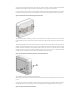
The proper orientation for the DIN rail clip is with the fixed (non spring-loaded) end up, and the spring-
The proper orientation for the DIN rail clip is with the fixed (non spring-loaded) end up, and the spring-
loaded end of the DIN rail clip at the bottom. This insures that the fixed end of the clip will bear the
loaded end of the DIN rail clip at the bottom. This insures that the fixed end of the clip will bear the
weight. The Ethernet port, M8 port and status LED are on the bottom side of the BreadCrumb ES1.
weight. The Ethernet port, M8 port and status LED are on the bottom side of the BreadCrumb ES1.
The mounting holes for attaching the DIN rail mounting bracket are accessible from the front of the
BreadCrumb ES1 enclosure via small flip-up accesses on the left and right borders of the front of the ES1
enclosure.
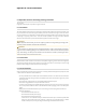
The following diagram shows the order of washers, lock washer and nut used when attaching one end of
the ES1 DIN rail mounting bracket to the enclosure of the BreadCrumb ES1. The DIN rail mounting brack-
et should be attached to both mounting holes of the BreadCrumb ES1.
Figure: Attaching the DIN Rail Mounting Bracket to the BreadCrumb ES1 (Top View)
The attachment order of parts from front to back are:
M4 machine screw, washer, BreadCrumb ES1 (front to back), DIN rail mounting bracket, washer, lock
washer, nut
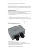
The DIN rail clip is attached to the end of the DIN rail mounting bracket using three machine screws.
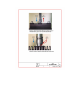
Figure: Attaching the DIN Rail Mounting Bracket to the BreadCrumb ES1 (Front View)
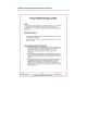
Figure: Attaching the DIN Rail Mounting Bracket to the BreadCrumb ES1 (Back View)