TM CHALLENGER 40 ARF TRAINER Assembly and Operations Manual First Edition 1999 11 30 Please Thoroughly Review This Manual and all other documentation and instructions Before Assembling or Operating the VMAR Challenger 40ARF Trainer Visit us on the Web at www.richmondrc.
VMAR CHALLENGER 40ARF TRAINER INTRODUCTION. Liability Disclaimer It is important that the following liability disclaimer be READ BEFORE ASSEMBLING OR USING THIS PRODUCT Thank you for purchasing a VMAR Product. VMAR Manufacturing is committed to delivering superior value to the RC modeller. Your new VMAR Challenger 40ARF Trainer is a market leader in features, value, ease of use and flexibility. Please review these instructions before beginning the simple assembly procedure.
VMAR CHALLENGER 40ARF TRAINER TM INDEX. Another feature that experienced RC flyers look for is "pinned" hinges that don't rely solely on the hinge glue to keep the control surfaces attached. Look no further. Turn over a Challenger wing and look at the outboard and inboard hinges...
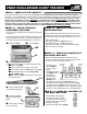
VMAR CHALLENGER 40ARF TRAINER PHASE 1 - CHECK OUT THE CONTENTS. TM PLEASE SAVE YOUR BOXES UNTIL CHECK OUT COMPLETE You’ve taken the lid off the box, read over the "READ ME FIRSTt" pamphlet and you are ready to start with the assembly procedure… you’re about 6-8 hours away from being ready to go flying! Now is the time to look over what’s in the box. Please go through the contents and make sure nothing has been damaged in shipping.
VMAR CHALLENGER 40ARF TRAINER R R STEP 1.5 - CHECK OFF CONTENTS OF THE MAIN GEAR PARTS BAG. R R STEP 1.7 - CHECK OFF CONTENTS OF THE CONTROL HORN PARTS BAG. Open the Control Horn Parts Bag and carefully remove the contents. Confirm that you have the following items and then return them to the Control Horn Parts Bag. R 2 Metal bolts [CHB] 2.5 mm x 2530 mm (1 to 1-3/16 in.) R 2 Plastic control horns [CHH] R 2 Plastic bevelled washers [CHW] R 2 Plastic T-nuts.
VMAR CHALLENGER 40ARF TRAINER TM R R STEP 1.11 CHECK OFF OTHER ITEMS NEEDED TO COMPLETE CHALLENGER. R R STEP 1.10 CHECK OFF TOOLS AND SHOP MATERIALS NEEDED. These tools & shop materials are not included and are required to complete & operate your Challenger and most other remote control aircraft. For some specific recommendations & part numbers please see the attached listing of tools & materials available in your market area.
VMAR CHALLENGER 40ARF TRAINER NOTES TM NOTES This page left intentionally blank This page left intentionally blank TM TM 7
VMAR CHALLENGER 40ARF TRAINER R R PHASE 2 - WING ASSEMBLY. R 2.2.2 You will also need the following items that are not included with your Challenger. R R STEP 2.1 - TERMS TO REMEMBER R Pencil R Masking tape. - First the easy part, the outboard ends of the wings are called the "wing tips". - Each wing half has a flat wooden face that is at the opposite end from the wing tips. This flat wooden face is called the "wing root".
VMAR CHALLENGER 40ARF TRAINER TM R 2.2.10 Check the entrance to the wing spar joiner R 2.2.15 Carefully and firmly slide the right wing towards cavity in the wing roots. There may be "flashing" or a thin skin of wood covering the entrance to the cavity which should be removed carefully with a sharp hobby knife. the left. Wiggle the wings slightly to encourage the two wing alignment dowels to mate with their respective receiving holes in the opposite wing root. R 2.2.
VMAR CHALLENGER 40ARF TRAINER R R STEP 2.2 - DRY ASSEMBLY OF THE WING HALVES cont'd. R 2.2.21 Place the wing right way up in the wing saddle TM R 2.3.5 To assemble and glue the wing you will need the two wing halves [WR] and [WL] and the following items from the Wing Parts Bag. R 1 Wing spar area of the fuselage. Place the four wing bolts into the wing bolt holes in the top of the wing and make sure you can screw them down into the wing bolt mounting blocks in the fuselage.
VMAR CHALLENGER 40ARF TRAINER R 2.3.10 Insert the end of the wing spar joiner that is cov- TM ered with glue into the wing spar joiner cavity of the left wing up to the pencil line on the wing spar joiner. Make sure the wing spar joiner is right way about. R R STEP 2.4 - APPLYING WING JOINT TAPE. R 2.4.1 Using the yellow YELLOW WING JOINT R 2.3.11 Apply 30 Minute Epoxy to the two dowel receiving TAPE [WJTY] holes in the wing roots of both the left and right wings. R 2.3.
VMAR CHALLENGER 40ARF TRAINER R R STEP 2.5 - INSTALLING THE AILERON SERVO INTO THE WING. R 2.5.1 To install the aileron servo into the wing you will need the following items: R Servo R Servo mounting screws and grommets as supplied with the servo R Servo control arm as supplied with the servo R Two aileron control rod [AC] assemblies from the wing parts bag. The assemblies consist of a metal rod with a plastic clevis screwed onto each end. R Masking tape. R Phillips Screwdriver. TM R R STEP 2.
VMAR CHALLENGER 40ARF TRAINER R 2.6.6 Connect the R 2.6.12 If when doing the tests noted in 2.6.10 and LEADING EDGE SERVO ARM CLEVIS clevises on the aileron control rods to the aileron servo arm. TM 2.6.11 the direction of aileron deployment is incorrect, consult your radio manual for how to reverse the direction of rotation of your servo.
VMAR CHALLENGER 40ARF TRAINER R R PHASE 3 - INSTALLING THE LANDING GEAR. TM R R STEP 3.2 - CHALLENGER MAIN LANDING GEAR INSTALLATION. The Challenger has a tricycle gear configuration ("trike gear") using a steerable nose wheel and main landing gear. Trike gear is recommended in trainers and makes it much easier to steer your model on the ground and to control it during take off. The main landing gear must be assembled before it can be installed. See Step 3.
VMAR CHALLENGER 40ARF TRAINER TM NOTES R 3.2.6 Locate the two main landing gear assemblies from Step 3.1 Carefully insert the wire end of each assembly into the holes at the end of the landing gear slots. We suggest rotating the assemblies back and forth and wiggling the wire down into the holes until the landing gear is just slightly away from contacting the fuselage. See the illustration below. MAIN LANDING GEAR ASSEMBLIES SLOT IN BOTTOM OF FUSELAGE FUSELAGE [F] BOTTOM VIEW LOOKING BACK FROM FRONT.
VMAR CHALLENGER 40ARF TRAINER R R STEP 3.3 - CHALLENGER NOSE GEAR ASSEMBLY. TM R R STEP 3.4 - CHALLENGER NOSE GEAR INSTALLATION. R 3.3.1 To assemble the nose gear The nose gear must be assembled before it can be installed. See Step 3.3 if you have not yet assembled the nose gear. you will need the following items from the Nose Gear Parts Bag. R 3.4.1 To install the nose gear you will need the fuse- R 2 Wheel collars [COL] with set lage [FS], the nose gear assembly from Step 3.
VMAR CHALLENGER 40ARF TRAINER TM R 3.4.6 Carefully push the control rod back into the R 3.4.10 There is a flat notch filed in the front face of the fuselage and position the steering arm so that it can be inserted into the recess in the nose gear block. nose gear wire that is intended to align with and provide a seat for the steering arm set screw. Push the nose gear wire down further into the nose gear block as you tighten the steering arm set screw onto the flat notch. NOSE GEAR BLOCK R 3.4.
VMAR CHALLENGER 40ARF TRAINER R R PHASE 4 - THE FUEL TANK & RECEIVER BATTERY PACK. TM R 4.1.5 Push the stopper firmly into the neck of the tank until the shoulder of the black stopper contacts the neck of the tank. The fuel tank is shipped in the Master Parts Bag. The pre-bent metal fuel outlet tubing, fuel stopper, cinch bolt and plastic retaining disks have been pre-assembled and inserted into the neck of the tank. The fuel clunk has also been placed into the tank. R 4.1.
VMAR CHALLENGER 40ARF TRAINER TM R 4.2.4 Trial fit the tank by inserting it from within the fuselage radio compartment, stopper end first with the metal tubes pointing up and pushing the tank gently FUEL forward until the metal TANK tubes and stopper pass STOPPER through the firewall. Adjust the angle of the metal tubes so that they still point upwards and clear the firewall with sufficient clearance to allow you to push the fuel tubing on to and over the metal tubes. R 4.2.
VMAR CHALLENGER 40ARF TRAINER R R STEP 4.3 - INSTALLING THE RECEIVER BATTERY PACK cont'd. TM R R STEP 5.1 - MOUNTING THE ENGINE. R 5.1.1 Remove the muffler, prop nut and prop washer from your engine. R 4.3.4 Thread the R 5.1.2 Use a 4 mm battery pack connector and wire back from the fuel compartment to the radio compartment.
VMAR CHALLENGER 40ARF TRAINER TM R 5.1.7 Confirm that the engine has sufficient clearance for the fuel tank lines, muffler, prop, spinner and throttle control arm. FUEL LINE R 5.1.8 Align the engine so that it is straight ahead or pointing a couple of degrees to the right but NOT pointing to the left. R 5.1.9 Confirm that the engine is aligned as explained above and then tighten the 4 black machine screws clamping the engine to the engine mount. .
VMAR CHALLENGER 40ARF TRAINER R R PHASE 6 - INSTALLING THE HORIZONTAL AND VERTICAL STABILIZERS R R STEP 6.1 - PREPARING THE HORIZONTAL STABILIZER. R 6.1.7 Hold the metal bolt and TH R 6.1.1 Remove the horizontal stabilizer [TH] with pre-installed elevator from its shipping bag. R 6.1.2 Locate a control horn TM TOP BOTTOM set from the Control Horn Parts Bag. A control horn set consists of... R 1 Metal bolt [CHB] 2.5 mm x 25-30 mm (1 to 1-3/16 in.
VMAR CHALLENGER 40ARF TRAINER R R STEP 6.2 - INSTALLING THE HORIZONTAL STABILIZER TM R 6.2.6 Use a light touch with a very sharp hobby knife to R 6.2.1 Firmly attach the wing to the fuselage using the four plastic wing bolts. Tighten the bolts snugly but do not over tighten. Go to the front of the fuselage, centre yourself and look back across the wing to the horizontal stabilizer. Check that the wing and the horizontal stabilizer are parallel to each other. R 6.2.2 Remove the wing and set it aside.
VMAR CHALLENGER 40ARF TRAINER R R STEP 6.3 - PREPARING THE VERTICAL STABILIZER. R 6.3.1 Remove the vertical stabilizer [TV] with preinstalled rudder from its shipping bag. R 6.3.8 Thread the plastic TM BOLT control horn [CHH] onto the exposed threaded end of the bolt that is protruding from the left side of the rudder. Screw the control horn on until the bolt end just protrudes from the control horn. Rotate the control horn so that it is "facing" towards the front. TV METAL BOLTS R 6.3.
VMAR CHALLENGER 40ARF TRAINER R R STEP 6.4 - INSTALLING THE VERTICAL STABILIZER. TM R 6.4.5 Peel the covering from the rectangular shaped cut out strips on either side of the vertical stabilizer and discard them. R 6.4.1 Precisely apply masking tape to the sides of the vertical stabilizer where the vertical stabilizer meets the top of the vertical slot in the fuselage. The masking tape will serve as an alignment guide for later.
VMAR CHALLENGER 40ARF TRAINER R R PHASE 7 - INSTALLING THE RADIO. TM R 7.1.8 Mount the rudder servo first with the servo output shaft more towards the front of the fuselage. Note the rudder servo location label on the servo tray. R R STEP 7.1 - INSTALLING THE SWITCH HARNESS AND THE RUDDER, ELEVATOR & THROTTLE SERVO'S. THROTTLE SERVO RIGHT ELEVATOR SERVO R 7.1.1 Locate the Servo Tray Parts Bag that you removed from the fuselage earlier. FRONT R 7.1.
VMAR CHALLENGER 40ARF TRAINER R R STEP 7.2 - CONNECTING THE THROTTLE CONTROL RODS TO THE THROTTLE SERVO. TM R 7.2.7 With the set screws facing upwards, loosen the set screws and slide the collars over both throttle control rods and tighten the two collars securely into place so that the two rods are joined firmly together. Ensure the collar set screws are facing upwards. R 7.2.1 Secure the engine throttle arm at roughly half throttle.
VMAR CHALLENGER 40ARF TRAINER R R STEP 7.4 - CONNECTING THE CONTROL RODS TO THE RUDDER AND ELEVATOR SERVOS. R 7.4.1 Consult the following illustration that shows how R 7.4.7 Attach an EZ connector [EZ] to the servo arm opposite from the rudder. Centre the nose wheel and cinch down the EZ connector to the nose gear steering control rod. the throttle, rudder and elevator servos are positioned and connected to their respective control rods.
VMAR CHALLENGER 40ARF TRAINER TM R R STEP 7.7 - CONFIRM RADIO OPERATION. R R STEP 7.5 - ADJUST CONTROL SURFACE THROW LIMITS. R 7.7.1 Consult your radio manual for instructions Adjust the throw limits for the control surfaces to match the following guidelines. about testing and operating your radio system. R ELEVATOR: 10 mm (3/8 in.) up & 10 mm (3/8 in.) down R 7.7.2 Pay particular attention to charging your radio Total movement 20 mm (3/4 in.) R RUDDER: 10 mm (3/8 in.) left & 10 mm (3/8 in.
VMAR CHALLENGER 40ARF TRAINER R R PHASE 8 - CHECK OUT R R STEP 8.1 - BALANCE THE AIRCRAFT. TM R R STEP 8.2 - SEALING THE FUEL TANK INTO POSITION. The Centre of Gravity is often referred to as the "CG" and is the point at which an aircraft is balanced with as much weight aft of the point as it has weight forward of the point. For your Challenger the CG should be located at 89 to 108mm (3-1/2 to 4-1/4 in.) back from the leading edge of the wing when the wing has been attached to the fuselage.
VMAR CHALLENGER 40ARF TRAINER TM CAUTION R 8.2.10 Carefully re-install the two pieces of silicone tubing that run from the tank metal pipes to the engine and muflfer. Ensure you install each piece on the correct metal pipe. You are ultimately responsible for the mechanical, aeronautical and electrical integrity of your Challenger and it's structure, control surfaces, hinges, linkages, covering, engine, radio, wiring, battery and all other components. Check all components before and after each flight.
OTHER VMAR PRODUCTS VMAR Manufacturing makes an extensive range of products including the VMAR Model Aircraft Test Stand and a full line up of Almost Ready to Fly “ARF” model aircraft that go from box to flight line in just hours. VMAR products are distributed through selected agents and hobby retailers worldwide. For further information about other VMAR products and how to purchase them in your area please visit our web site at www.richmondrc.