
Instruction manual


29
VMAR CHALLENGER 40ARF TRAINER
TM
RR
RR
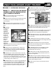
RSTEP 7.5 - ADJUST CONTROL SUR-
FACE THROW LIMITS.
RR
RR
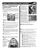
RSTEP 7.7 - CONFIRM RADIO OPERA-
TION.
RR
RR
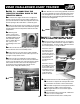
RSTEP 7.6 - INSTALLING THE RECEIVER.
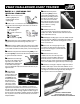
Adjust the throw limits for the control surfaces to match
the following guidelines.
You can reduce the amount of throw by doing either
or both of the following...
- From the servo end, move the clevis to a hole in the
servo arm that is closer to the servo output shaft.
- From the control horn end, move the horn out further
on the threaded shafts. Always confirm that the horn
is still thoroughly engaged with the threaded shaft
after you have adjusted it.
RR
RR
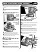
R7.6.1 Consult your radio manual for instructions
about hooking up your receiver, switch harness, battery
pack and servos.
RR
RR
R7.6.2 Plan where you are going to put the receiver
with consideration for routing the antenna safely and
connecting to your battery pack and servos. Consult your
radio manual for their recommendations about receiver
location.
RR
RR
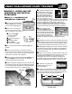
R7.6.3 Wrap the receiver securely in foam suitable for
RC equipment and wrap the foam insulated receiver in a
plastic bag or cling wrap.
RR
RR
R7.6.4 Generally in the absence of specific instructions
from the radio manufacturer, it is recommended that the
receiver be placed where it is least likely to suffer dam-
age from impact during a crash. Keep the battery pack
and other heavy loose items ahead of the receiver.
RR
RR
R
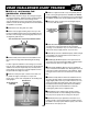
7.7.1 Consult your radio manual for instructions
about testing and operating your radio system.
RR
RR
R7.7.2 Pay particular attention to charging your radio
system batteries and range testing the system before
and after each flight.
RR
RR
R7.7.3 Check that all controls are working correctly
before and after each flight.
Caution: You are ultimately responsible for the
mechanical, aeronautical and electrical integrity of
your Challenger and it's structure, control surfaces,
hinges, linkages, covering, engine, radio, wiring,
battery and all other components. Check all compo-
nents before and after each flight. Don't fly until it's
right!
RR
RR
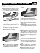
RELEVATOR: 10 mm (3/8 in.) up & 10 mm (3/8 in.) down
Total movement 20 mm (3/4 in.)
RR
RR
RRUDDER: 10 mm (3/8 in.) left & 10 mm (3/8 in.) right
Total movement 20 mm (3/4 in.)
RR
RR
RAILERONS (both left and right):
6 mm (1/4 in.) up & 6 mm (1/4 in.) down
Total movement 12 mm (1/2 in.)
Note: Throws are measured at the widest part of the
elevator and rudder.
Do NOT exceed these control surface throw recommen-
dations when you are using the Challenger as a trainer.
TM
This space left intentionally blank