
Instruction Manual

Table Of Contents
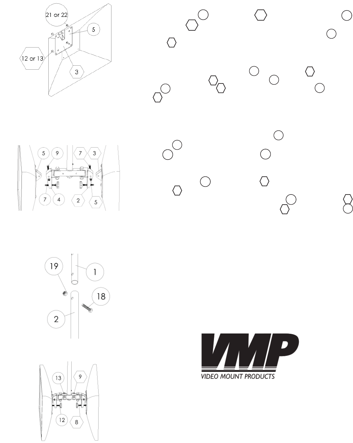
Step 5
Use either the M4 (#22 LCD-1CB and #12 LCD-CM2B) or the M5 (#21
LCD-1CB and #13 LCD-CM2B) screws as appropriate for your fl at
panels to attach your fl at panels to the mounting plates (
#5 LCD-
1CB and
#3 LCD-CM2B).
Step 6
Through bolt the mounting plates (#5 LCD-1CB and #3 LCD-CM2B)
to the pivot brackets (
#2 LCD-CM2B and #4 LCD-1CB) using the M6
screw (
#9 LCD-1CB and #7 LCD-CM2B) and nylon nut (#7 LCD-1CB
and
#5 LCD-CM2B).
Step 7
Determine the height at which you want to mount the fl at pan-
els and through bolt the extension tube (
#2 LCD-1CB) to the ceil-
ing plate (
#1 LCD-1CB) at the appropriate height using the 5/16”
screw (
#18 LCD-1CB) and nylon nut (#19 LCD-1CB).
Step 8
Insert cable clips (
#13 LCD-1CB and #9 LCD-CM2B) into the sup-
port tube (
#1 LCD-CM2B) for cable management. To adjust the tilt
of the fl at panels thread the adjusting screw (
#12 LCD-1CB and #8
LCD-CM2B) further into the pivot bracket (#2 LCD-CM2B and #4
LCD-1CB) to increase the tilt up and back to adjust the tilt down.
Please verify that all nuts and screws are securely tightened.
Step 5: Attaching the fl at panel to
the mounting plate
Step 6: Attaching the mounting
bracket to the pivot bracket
Step 7: Attaching the extension tube
to the ceiling plate
Step 8: Final adjustments
WARNING: The installer of these products must verify that the mount sur-
face, ceiling or wall, will safely support the combined weight of all at-
tached equipment and hardware. Video Mount Products will not be held
liable for the improper use or installation of its products.
Enjoy Your Mount!
12
22
13
21
5
3
5
3
4
2
9
7
7
5
2
1
19
18
13
9
1
12
8
4
2