VIDEO MOUNT PRODUCTS Instruction Sheet For: LCD-PV For more information, please contact us at: 325 Log Canoe Circle, Stevensville, Maryland 21666 (T) 410.643.6390 / (F) 410.643.6615 www.videomount.
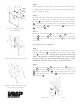
Step 1 Before starting, lay out all parts to your mount and match them to the parts list provided. Verify that you have all your parts before attempting to assemble the mount. Step 2 Determine the VESA standard that your TV follows to determine which VESA plate you will be using. For VESA 75 or 100 use the small mounting plate 5 and for VESA 200 or 100x200 use the large mounting plate 6 .
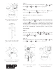
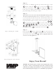
Step 6 Attach your monitor to the chosen mounting plate 5 or 6 using the M4 21 , M5 22 or M6 33 screws as appropriate. Step 7 Connect the extension tube 2 to the ceiling plate 1 using the 5/16” screw 18 and nylon nut 19 . Proceed to step 12. If you plan to use 1.5” NPT as a ceiling mast, Step 8 Step 6: Attaching the monitor Mark the ceiling or desired mounting surface in preparation of in- (monitor not included) stallation of ceiling plate 42 .
Step 11 Screw in the 1.5” NPT pipe into the top of the female pipe couple 37 and the ceiling plate 42 . Screw ¼” brake screws 36 into the top of the female pipe couple 37 and ceiling plate 42 so the brake screws are tight against the pipe. This will help prevent the pipe from turning out of the pipe couples. Step 12 If you desire to use the camera bracket then follow this step, otherwise proceed to the next step. First determine if you wish the camera to be mounted below or to the side of the monitor.