
InstructionSheet
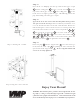

Step 11
Screw in the 1.5” NPT pipe into the top of the female pipe couple
and the ceiling plate . Screw ¼” brake screws into the
top of the female pipe couple and ceiling plate so the
brake screws are tight against the pipe. This will help prevent the
pipe from turning out of the pipe couples.
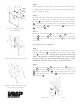
Step 12
If you desire to use the camera bracket then follow this step, other-
wise proceed to the next step. First determine if you wish the cam-
era to be mounted below or to the side of the monitor. Then deter-
mine how long the camera arm needs to be to extend past the side
or bottom of the monitor. Use the connectors provided , &
to extend the L connector as needed. Take the end as-
sembly , , , & and screw it to the connector ,
, or furthest from the center of the mount. Make sure
the M6 brake screws are tight in the swivel metal .
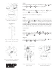
Step 13
Insert end plug into the support tube . For cable manage-
ment, insert the cable clips by pushing the arrow ends into the
square holes in the support tube . Please verify that all nuts and
screws are securely tightened.
Step 11: Inserting the 1.5” NPT
Step 12: Using the camera bracket
VIDEO MOUNT PRODUCTS
WARNING: The installer of these products must verify that the mount-
ing surface, ceiling or wall, will safely support the combined weight
of all attached equipment and hardware. Video Mount Products will
not be held liable for the improper use or installation of its products.
Enjoy Your Mount!
3
3
37
42
36
14
13
25
24
26
27
32
28
29
24
30
25
31
26
32
31
29
37
42