
Operating instructions


5
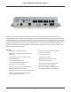
VOCIA PAGING STATION KIT (PSKIT-1) FRONT PANEL
Setup and Use
The Vocia software provides an intuitive interface for conguration, DSP equalization and programming of the PSKIT-1. The information supplied
by this manual relates to physical connections and assignment. For more details on software setup, please consult the Vocia Help File.
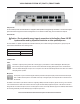
Power Indicator
Caution - Due to potential energy hazard, connections to the Auxiliary Power 24V DC
inputs must be made by a qualied electrician or other qualied person
The Vocia PSKIT-1 is capable of operation from both PoE and 24V DC power. If both are being used, PoE power is given priority. The
Power Indicator LED behaves in the following manner:
LED Description
None No power
Solid green Powered
CONNECTIONS
Power
The PSKIT-1 supports powering via 802.3af or 802.3at (Type 1) PoE switches or external PoE Supplies. Alternatively the
device can be powered using the Power connector and an external 24V DC supply. Both supplies can be connected at the
same time without affecting the unit. Upon loss of one power source the unit automatically switches to the other source without
interrupting device operation.
Microphone
A microphone may be connected using the external 3-pin balanced microphone input provided. The default nominal input
level is -50dBu. Phantom power is not available on this input. If using this input, the microphone and its connection will not
be monitored.
The PSKIT-1 also includes a 5-pin internal connector for supporting a Biamp monitored microphone (optional accessory). This connection
is not accessible from the outside of the enclosure and must only be used with a Biamp supplied microphone. If the internal connector is
being used with a monitored microphone, the LK1 and LK2 jumpers must be removed. By default the jumpers are installed, which disables
the monitoring functionality so that a standard (3-pin) microphone may be used.
Do not use both the internal and external microphone connections at the same time.