
Operating instructions


7
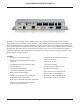
VOCIA PAGING STATION KIT (PSKIT-1) FRONT PANEL
RS-232
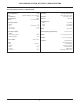
A female RS-232 serial port is provided for Vocia Text Protocol (VTP) connectivity. Please refer to the software help le for all supported
commands.
Pin Out Function
Pin 2 Transmit Data TXD output
Pin 3 Receive Data RXD input
Pin 5 GND / 0V
Aux Port
A RJ-45 connector is available internally for use with Biamp accessories. This port is not an Ethernet port and must not be connected to a
switch, PoE supply, or other Ethernet network devices.
Network Connection
The PSKIT-1 is a CobraNet device and uses the RJ-45 connector for communications with other Vocia devices. It is possible to use this
network connection with an 802.3af or 802.3at (type 1) PoE switch or external PoE Supplies to provide power to the device. Alternatively,
if the device is being powered using the Power Connector and an external 24V DC supply, a connection to the CobraNet network must
still be available for the device communications. All CobraNet routing and bundle assignments are processed by the Vocia devices locally.
Vocia makes dynamic use of available bundles in CobraNet. A 100Base-T Ethernet switch (not repeater hub) is required when networking
multiple units. CobraNet utilizes standard CAT5, CAT5e, CAT6, or CAT7 cabling, which has a specied maximum length of 328 feet (100
meters). Additional Ethernet switches, or switches which provide ber-optic interface, can be used to extend the physical distance between
units within a network. Please note that CobraNet limits network extensions to 7 hops (one-way transmissions) within a network. The RJ-45
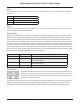
connector provides two LEDs that indicate Ethernet link and network activity.
Left LED Right LED Description
None None No Data Connectivity or CobraNet activity.
Amber Flashing green Link established and CobraNet activity detected. The unit is acting as
the CobraNet Performer.
Flashing amber Flashing green Link established and CobraNet activity detected. The unit is acting as
the CobraNet Conductor.
Flashing amber None CobraNet fault. Check cabling and conguration for errors.
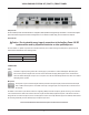
Device ID switches
The rotary ID switches are located on the front of the unit and are used to provide a unique Device ID. The
switches are in hexadecimal format. All Vocia units of the same type must have a unique Device ID to function
properly within a Vocia Paging World (for instance, it is not possible to have two Vocia Devices of the same
type with the same Device ID of hex 07).
As an example, to assign a Device ID of hex 07, turn the LSB switch to 7 and leave the MSB switch on 0. To create an ID of hex B7, turn the
LSB switch to 7 and turn the MSB switch to B. Device ID switches should be set using a 0.1 inch (2.5mm) to 0.12 inch (3.0mm) at blade
screwdriver. More information on setting IDs and the hexadecimal numbering scheme used can be found in the Vocia Software Help File.