
User's Manual


10
Connecting Audio Output
There are 3 outputs available from which to get audio: the individual (Ch.1/Ch.2) channel outputs and the
single mixed output. Depending on which jacks are used will determine the amount of volume control on the
mi xe r/s oun d s y s t em.
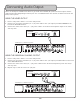
USING THE MIXED OUTPUT
1. Ensure main power switch is set to the OFF position.
2. Connect one end of the included 1/4” - 1/4” patch cable to the 1/4” output jack labeled MIXED on the
back of the IR-9009 Receiver.
3. Connect the other end of the 1/4” - 1/4” patch cable in to the desired microphone input on the mixer/
sound system.
USING THE INDIVIDUAL CHANNEL OUTPUT
1. Ensure main power switch is set to the OFF position.
2. Connect one end of the included 1/4” - 1/4” patch cable to the 1/4” output jack labeled CH.1 on the back
of the IR-9009 Receiver.
3. Connect the other end of the 1/4” - 1/4” patch cable into the desired microphone input on the mixer/
sound system.
4. Repeat steps 2 & 3 for the CH. 2 1/4” jack.
use of this jack
disables front sensor
(Example of Mixer Inputs)
use of this jack
disables front sensor
(Example of Mixer Inputs)