
User's Manual


12
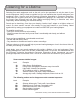
Descriptions and Details
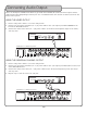
RECEIVER
1. Power - This switch turns the power OFF/ON to the system.
2. IR Sensor - This detects and receives the signals from the hand held microphones.
Note: The microphones need to have line-of-sight to at least one receiver for continuous audio.
3. Ch.1 Volume - This alters the volume for Microphone 1.
4. CH.1 Signal LED - This LED registers the signal from Microphone 1.
Note: The LED will shine when connected to its respective mic.
5. CH.2 Volume - This alters the volume for Microphone 2.
6. CH.2 Signal LED - This LED registers the signal from Microphone 2.
Note: The LED will shine when connected to its respective mic.
RECEIVER - BACK PANEL
1. AC In - This is where the power adapter is plugged in.
2. Mixed Output - This 1/4” jack outputs the audio signals from both Microphone Channel 1 & 2.
3. Ch.1 Output - This 1/4” jack outputs the audio signal from Microphone 1 only.
4. Ch. 2 Output - This 1/4” jack outputs the audio signal from Microphone 2 only.
5. Sensor Inputs - These 1/8” jacks are where the External IR Sensors are plugged in.
Note: The 1/8” Sensor Input that is highlighted with the white square will disable the main front IR Sensor, if used.
use of this jack
disables front sensor