
Operating instructions


8
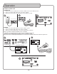
Descriptions and Functions
TRANSMITTER
FRONT PANEL
1. Power - Turns transmitter module ON/OFF.
2. VOL +/- - Alters the volume up and down.
3. CH +/- - Cycles through the operating channel number.
4. TX Light - Indicates a signal is being transmitted to the transmitter.
5. LED Readout - Displays the current operating channel number.
6. Antenna - Connect antenna here.
REAR PANEL
1. Multi-Purpose Jack - Used to patch transmitter into a compatible
Vocopro unit.
2. TX Power Level - Sets power used in transmitting signal to receiver:
L - Low
M - Medium
H - High
3. Audio Input - Connect audio source here.
4. Power - Connect USB power cord here.
RECEIVER
FRONT PANEL
1. Power - Turns receiver module ON/OFF.
2. Vol +/- - Alters the volume up and down.
3. RX Light - Indicates a signal is being received from the transmitter.
4. LED Readout - Displays the current operating channel number.
5. Antenna - Connect antenna here.
REAR PANEL
1. Multi-Purpose Jack - Used to patch receiver into a compatible Vocopro
unit.
2. Left/Right Stereo Switch - Changes the receiver audio output from:
L - Left-mono
S - Stereo
R - Right-mono
3. Audio Output - Sends received audio signal out.
4. Power - Connect USB power cord here.
Note: There is no manual syncing required; power on both transmitter and
receiver modules to establish a connection. The channel changed on the
transmitter will automatically be communicated to the receiver.
VOL+
TRANSMITTER
CH+ CH-
VOL-
AIR-NET 2
1
2
6
5 4
3
Front Panel
AUDIO
IN
MULTI-PURPOSE
JACK
+5V
L M H
1
2
3
4
Rear Panel
VOL+ VOL-
AIR-NET 2
RECEIVER
1
3
2
5
4
Front Panel
AUDIO
OUT
MULTI-PURPOSE
JACK
+5V
L S R
1
2
4
3
Rear Panel