a u n a m 1 2 3 4 (BALANCED) (BALANCED) (BALANCED) CROSSFADER VIDEO TOGGLE VIDEO 1 VIDEO 2 DSP KEY CONTROL AND CROSSFADER VIDEO TOGGLE VIDEO 3 LIGHT (DC 12V) LEFT AV 1 AV 2 AV 3 PH 1/LINE PH 2/LINE PH 3/LINE CD 1 CD 2 CD 3 STEREO 1 (BALANCED) STEREO 2 -26 -20 -17 -14 -10 -6 0 +3 +6 +9 +10 +15 ' RIGHT OUTPUT LEVEL DISPLAY STEREO 3 POWER GAIN GAIN GAIN SIGNAL GAIN -20 GAIN SIGNAL +6 -20 GAIN +6 SIGNAL -20 GAIN +6 AV OUT LEVEL POWER AMP LEVEL VOCAL EFFECTS MANUAL
Safety Instructions 8. Ventilation - The appliance should be situated so its location does not interfere with its proper ventilation. For example, the appliance should not be situated on a bed, sofa, rug, or similar surface that may block the ventilation slots. CAUTION RISK OF SHOCK CAUTION: To reduce the risk of electric shock, do not remove cover (or back). No userserviceable parts inside. Only refer servicing to qualified service personnel. 9.
FCC INFORMATION (U.S.A.) CAUTION: READ THIS BEFORE OPERATING YOUR UNIT 1. IMPORTANT NOTICE: DO NOT MODIFY THIS UNIT!: This product, when installed as indicated in the instructions contained in this manual, meets FCC requirements. Modifications not expressly approved by Vocopro may void your authority, granted by the FCC, to use this product. 1. To ensure the finest performance, please read this manual carefully. Keep it in a safe place for future reference. 2.
Listening For A Lifetime Selecting fine audio equipment such as the unit you’ve just purchased is only the start of your musical enjoyment. Now it’s time to consider how you can maximize the fun and excitement your equipment offers. VocoPro and the Electronic Industries Association’s Consumer Electronics Group want you to get the most out of your equipment by playing it at a safe level.
PKJ-9090PRO Professional Power Mixer with DSP Key Control and Crossfader Video Toggle Table of Contents Safety Instructions ................................................................................... 1 FCC Information....................................................................................... 2 Listening For A Lifetime ............................................................................ 3 Table of Contents .........................................................................
Specifications Inputs Sensitivity: MICRO 1,2,3,4 (TOP) ..................................................1.5mV/1K ohms (Balanced XLR Jack) AV/CD ......................................................................150mV/10K ohms (RCA Jack) PHONO .....................................................................3.0mV/47K ohms (RCA Jack) Outputs: MASTER OUTPUT .......................................................1.5V/600 ohms (XLR Jack/Balance) ............................................................
Welcome…. And Thank you for purchasing the PKJ-9090PRO from VocoPro, your ultimate choice in Karaoke entertainment! With years of experience in the music entertainment business, VocoPro is a leading manufacturer of Karaoke equipment, and has been providing patrons of bars, churches, schools, clubs and individual consumers the opportunity to sound like a star with full-scale club models, in-home systems and mobile units.
Mounting To mount, carefully place the PKJ-9090PRO in the rack space of your case. The PKJ-9090PRO takes 4 screws to mount. Make sure holes are aligned evenly. Use an alternating “X” rotation when screwing to ensure even tension and alignment. (See diagram below) 1 3 4 2 You will need: • 19” Rack Case • 4 Mount Screws • Phillips-head Screwdriver Note: When top mounting, make sure you have at least 2 rack-spaces available.
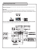
Getting Connected Below we provide some general information to help understand how a professional Karaoke system works and how it is connected. Signal Path When connecting your professional Karaoke system, the key is keeping in mind the signal path from the source music into your PKJ-9090 and out to your monitor, amp and speakers. Understanding the signal path before installation will make the process easier and most likely save you lots of time! Below is a diagram illustrating a basic signal path.
Microphone Panel Descriptions and Functions 1. XLR or ¼” MICROPHONE/LINE INPUTS - This combination input can be used to connect either a low impedance (XLR), high impedance (¼”) microphone or line-level device. The ¼” INPUT jack is located in the 1 center of the jack housing. The XLR INPUT jack is located within the outer perimeter of the jack housing.
Middle Panel Descriptions and Functions 1. VIDEO SELECT toggle - Holding this switch in the CROSSFADER position for a second, toggles video selection options between either CROSSFADER activation and MANUAL. When in CROSSFADER mode, the LED above CROSSFADER VIDEO TOGGLE will illuminate blue. This indicates that video ouput signal is recieved from the two assigned sources in the crossfader ASSIGN selections.
Middle Panel Descriptions and Functions Cont... TH DSP KEY CONTROL AND CROSSFADER VIDEO TOGGLE CROSSFADER VIDEO TOGGLE (BALANCED) VIDEO 1 2 4 GAIN VIDEO 3 AV 1 AV 2 AV 3 PH 1/LINE PH 2/LINE PH 3 CD 1 CD 2 CD 3 STEREO 2 STEREO 1 0 5 0 VIDEO 2 STEREO 3 0 0 5 3 SIGNAL 10 4 SIGNAL +6 -10 GAIN 1 0 -10 SIGNAL +6 GAIN VOCAL EFFECTS -10 +6 GAIN 6 MANUAL PARTNER ELIMI. MULTI. -15 10.
Master Panel Descriptions and Functions LIGHT (DC 12V) LEFT -38 -30 -20 -10 -7 -4 -2 0 +2 +4 +7 +10 (BNC) PH 3 RIGHT CD 3 3 OUTPUT LEVEL DISPLAY STEREO 3 L 2 1 VIDEO 3 AV 3 0 5 +6 GAIN 0 0 10 A/V OUT LEVEL +12 2. 12V LIGHT JACK (BNC) - This BNC style jack is for connecting a 12V DJ LIGHT, ideal for mixing in dark environments. POWER 5 5 4 -10 1. LED METERS - These meters display system OUTPUT LEVELS.
Master Panel Descriptions and Functions Cont... LIGHT VIDEO 3 (DC 12V) LEFT AV 3 -38 -30 -20 -10 -7 -4 -2 0 +2 +4 +7 +10 (BNC) PH 3 RIGHT CD 3 11. PHONES LEVEL - This control adjusts the headphones volume level when cueing. Turn clockwise for more volume and counter-clockwise for less volume. Note: Volume output may be much louder when CHANNEL cueing than MASTER cueing. It is recommended to adjust this level prior to toggling between cue options. OUTPUT LEVEL DISPLAY STEREO 3 SIGNAL 10.
Rear Panel (Mixer) Descriptions and Functions 1. BOOTH OUT - These ¼” jacks are for sending audio to BOOTH/MONITOR speakers. The output level to the BOOTH/MONITOR speakers is controlled via the BOOTH fader. Connect an appropriate cable from these jacks to your BOOTH/MONITOR speakers. Note: If your Booth/Monitor speakers do not have a built-in amplifier, you will need to connect them to a dedicated amplifier to power them. 2.
Rear Panel (Mixer) Descriptions and Functions Cont... 9. MICROPHONE INSERTS - These jacks are for connecting out-board effects units. The audio from the MIC channels are routed out from the INSERT jacks to your out-board effects unit(s) and routed back with the effects applied, using only a single cable. In order to use these jacks, you will need appropriate TRS (tip = send, ring = return, sleeve = signal ground) insert cables. 10. GROUND TERMINALS - These TERMINALS are for connecting ground wires.
Rear Panel (Amp) Descriptions and Functions 1. SPEAKER/BRIDGE OUTPUTS - This connection outputs to speakers using “banana cables”. You have the option of using the Bridge configuration or the Stereo configuration. See the OPERATIONS section for instructions on using the STEREO or BRIDGE configuration. 2. GROUND LIFT switch - A “ground loop” is a phenomenon where an unintended connection to ground is made through an interfering electrical conductor, causing what is known as “60Hz hum.
Advanced Operations ESSIONAL KARAOKE MIXER WITH DSP KEY CONTROL AND CROSSFADER VIDEO TOGGLE CROSSFADER VIDEO TOGGLE Digital Key Control NCED) (BALANCED) (BALANCED) (BALANCED) VIDEO 1 VIDEO 2 VIDEO 3 LEFT AV 1 AV 2 AV 3 PH 1/LINE PH 2/LINE PH 3 CD 1 CD 2 CD 3 -38 -30 -20 -10 -7 -4 RIGHT Using Digital Key Control Use the Digital Key Controller to obtain the a musical STEREOof 3 your voice.
Advanced Operations Cont... Digital Echo PROFESSIONAL KARAOKE MIXER WITH DSP KEY CONTROL AND CROSSFADER VIDEO TOGGLE Customizing Digital Echo settings (See Figure 1) CROSSFADER VIDEO 2 VIDEO 3 1 VIDEO TOGGLEthe VIDEO When using Digital (BALANCED) Echo, you can customize the effect by adjusting ECHO, REPEAT and DELAY controls. (BALANCED) (BALANCED) (BALANCED) First set the ECHO level control to 5. Then customize the effect with the REPEAT and DELAY level controls.
Advanced Operations Cont... Talk Over Making an announcement during playback To make an announcement during music playback, you most likely will want the music at a low enough volume so that you can be heard over the music clearly. To do this, you use the TALK OVER function(pg 9, #9) when the toggle is set to ON, the music volume is lowered considerably to allow for the announcement. When done with the announcement, you switch the toggle back to OFF to return the music back to the level it was originally.
Advanced Operations Cont... Master Cueing Master Cueing will cue the MASTER OUTPUT to the headphones. This is commonly used to isolate the audio signal to the headphones. Master cueing makes it possible to practice when “audible” music is not permitted i.e. late night practicing at home. To MASTER CUE, make sure the CUE/MASTER button is set to MASTER and adjust the CUE LEVEL control to a desired volume level.
Advanced Operations Cont... Bridge Operation 1. Set the STEREO/BRIDGE switch to the BRIDGE position. 2. With the PKJ-9090’s power OFF, connect the banana plug cables from the speaker’s output to the STEREO.BRIDGE input horizontally. When using the bridge connection, only one cable can be used. (-) (+) (-) (-) (+) (+) (-) Bare wire (+) Banana plug STEREO AND BRIDGE OUTPUT CONFIGURATIONS Stereo Operation 1. Set the STEREO/BRIDGE switch to the STEREO position. 2.
Troubleshooting Problems Possible Cause(s) Solution(s) Source toggle switch is set incorrectly Change source toggle to the correct setting Gain or master levels are turned down Raise gain and master levels to an appropriate level External device(s) are either not connected or not working properly Check external device(s) connections and viability Player source is not properly connected to the KJ-7800 Video in, or the KJ-7800 out to the display monitor Check all video connections in from the player
Vocopro 2005 V 1.1 WWW.VOCOPRO.