
Specifications


11
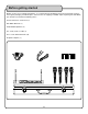
Front and rear panel descriptions and functions
1. ANTENNAS - Provide both RF and AF signals.
2. POWER (LED) - Indicates whether the UHF-5800 is ON or OFF. When it is lit, the power is ON.
3. RF (LED) - Lights when RF signals are received from the microphone channels.
4. AF (LED) -
Lights when AF signals are received from the microphone channels.
5. SQUELCH controls - Manual controls for controlling each microphone’s signal strength for best perfor
-
mance. Turn clockwise to increase SQUELCH control and turn counter-clockwise to decrease SQUELCH
application.
6. VOLUME controls - Adjusts the individual VOLUME of the receiver’s 4 microphone channels.
7. MICROPHONE modules - Contains the SQUELCH and VOLUME controls for each of the 4 wireless micro
-
phones. Each module can be easily removed individually.
8. POWER button - Turns the UHF-5800 ON/OFF.
9. AC POWER connection - Main power jack for connection to an AC electrical outlet or power strip/surge
protector.
10. MIXED OUTPUT - This ¼” unbalanced output jack is for output connection to amplifiers, effects devices
or mixers. All mic channels are output through this jack for mixed output.
11. XLR AUDIO OUTS - These XLR balanced output jacks are for output connections to amplifiers, effects
devices or mixers. These are for separate mic channel connections with unmixed mic output.
1
5
6
7
9
10
11
3
4
2
8