
Specifications


VGZ-005 / 20100616 BX42E / Page 5
Vogelzang International Corp.
CONNECTOR PIPE INSTALLATION
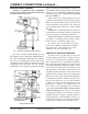
Fig. 3 – Stovepipe/Flue Connections
CORRECT WRONG WRONG
1. The smooth end of the stovepipe fits over the
cast iron damper collar. Secure with three (3)
sheet metal screws.
2. Horizontal pipe runs must slope upwards
towards the chimney at least 1/4” per foot of
horizontal run.
3. You must have at least 18 inches of clearance
between any horizontal piping and the ceil-
ing.
4. The pipe cannot extend into the chimney flue
(figure 3).
5. Secure pipe/elbow sections with three (3) sheet
metal screws at each joint to make the piping
rigid.
6. It is recommended that no more than two (2)
90° bends be used in the stovepipe installa-
tion. The use of more than two 90° bends may
decrease the amount of draw and possibly
cause smoke spillage. Where possible, use only
corrugated (nonadjustable) elbows. These
provide a better seal.
7. The connector pipe must not pass through an
attic or roof space, closet, or any concealed
space, or floor, ceiling, wall or combustible
construction. A UL 103 HT Listed chimney
must be used from the first penetration of
ceiling or wall to the chimney cap. Never use
single wall connector pipe as a chimney - a
house fire could result.
NOTE: STOVE PIPE IS NOT INCLUDED.
TO PURCHASE PIPE, VISIT YOUR LOCAL
HARDWARE, HOME OR BUILDING CEN-
TER. SEE “LOCATING STOVE” PAGE 3 FOR
ADDITIONAL SPECIFICATIONS.