
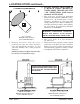
user manual


TR008 / 050207.2 DURANGO™ / Page 3
ASSEMBLY INSTRUCTIONS
tools
TOOLS AND MATERIALS REQUIRED FOR INSTALLATION
• Pencil
• 6 foot Folding Rule or Tape Measure
• Tin Snips
• Drill: Hand or Electric
• 1/8” dia. Drill Bit (for sheet metal screws)
• Screwdrivers (blade and Phillips type)
• 14mm Nut Driver or Ratchet with 14mm Socket
• Safety Glasses
• Gloves
materials
(NOTE: The following items are NOT included with your stove)
Flooring Protection: 29” x 48” as specified (see page 4)
Chimney Connection Pipe: 6” black steel (24 ga. min.) straight
stove pipe or elbow (as required)
1/2” Sheet Metal Screws
Chimney: Existing 6” Lined Masonry Chimney or 6” Inside Dia.
Listed Type HT chimney.
Furnace Cement (manufacturer recommends Rutland Code 78
or equivalent)
CAUTION: STOVE IS HEAVY. MAKE SURE YOU
HAVE ADEQUATE HELP AND USE PROPER
LIFTING TECHNIQUES WHENEVER MOVING
STOVE.
NOTE: Reference numbers correlate to exploded view and
parts list shown on pages 16 & 17.
1. Uncrate the stove and remove cardboard pack-
ing and protective poly bag. Remove bottom
heat shield (#16) from carton. (Save cardboard
for further assembly.)
2. Remove parts from inside stove. Parts include:
Blower Assembly (#29), Legs (#5) and Hard-
ware Pack (#26-28) located inside firebox.
NOTE: Stove body is HEAVY. Make sure
you have adequate help to lift stove body and
use proper lifting techniques. Stove may be
lightened during installation by removing fire
brick. Replace firebrick before using. There are
five different sizes of brick. Note the location
of each while removing or refer to figure 6 for
proper location inside firebox.
3. Place flattened carton on floor to protect stove
finish and lay stove onto it’s side.
4. Remove the hex nuts (#28) from the leg mount-
ing studs on the four corners of the bottom of
the stove.
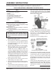
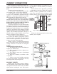
5. Position the bottom heat shield, figure 1, align-
ing the corner holes with the four leg mounting
studs. The smaller cutout must align with the
air intake in the bottom front of stove. NOTE:
The stove MUST NOT be operated without the
bottom heat shield in place.
NOTICE: Vogelzang International Corp. grants no warranty, stated or implied, for the installation or maintenance of
your wood stove and assumes no responsibility of any incidental or consequential damages.
6. Align each leg with the mounting stud and slide
into place. Replace the leg mounting hardware
(hex nut, fig. 1) after installing the leg. After
all four legs have been installed, tighten all
mounting hardware.
7. Return the stove to the upright position.
Fig. 1 – LEG ASSEMBLY
Bottom Heat Shield and Leg assembly
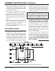
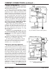
8. Attach the back heat shield assembly (#2) to the
rear of the stove. The closed end is positioned
to the bottom of the stove with the open end
up, fig. 2. Secure the back heat shield with
four Phillips head machine screws using the
threaded holes located in the rear side corners
of the stove.
9. Attach the heat shield deflector (#17) to the
top of the back heat shield assembly with three
Phillips head machine screws. The angled lip
of the deflector should face toward the front of
the stove.
Fig. 2 – TOP VIEW
Back Heat Shield and Deflector Assembly
Continued on next page