
user manual


Page 4 / DURANGO™ TR008 / 050207.3
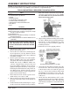
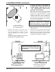
LOCATING STOVE
Fig. 3 – TOP VIEW Minimum Clearance Dimensions from Combustible Surfaces
FLOOR
PROTECTOR
DASHED LINES SHOW HORIZONTAL CHIMNEY CONNECTOR
AND ADDITIONAL FLOOR PROTECTOR REQUIRED BENEATH
AND EXTENDING 2” BEYOND EACH SIDE
NON COMBUSTIBLE CONSTRUCTION IN ACCORDANCE WITH NFPA 211
BACKWALL
SIDEWALL
30"
4 8"
18"min.
6"min.17"
22"
min.
11"min.
TOP VIEW
29"
1. The stove must be placed on solid concrete,
solid masonry, or when installed on a com-
bustible floor, on a listed floor protector, such
as Hy-C or Imperial Model UL 3648BK or
equivalent with 0.8 R-factor. (NOTE: to calcu-
late R-value of alternative materials see page
20). The floor protector must extend at least
18” beyond the front of the access door, 6” to
the sides, and must extend under and 2 inches
Continued on next page
beyond either side of the stove pipe if it is
elbowed towards a wall. (See figures 3 & 5 and
consult local building codes and fire protec-
tion ordinances). A grouted ceramic floor tile
installed per local building code is considered
a durable equivalent.
CAUTION: (FIre HAzArd) CArpeTINg ANd
OTHer COmbUsTIble mATerIAl sHAll
NOT COver THe FlOOr prOTeCTOr. THese
mATerIAls mUsT remAIN OUTsIde OF
COmbUsTIble CleArANCes, see FIg. 3 – 5.
2. The stove must have its own flue. Do not
connect this unit to a chimney
flue serving other appliances.
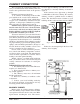
3. After observing the clearances to combus-
tible materials (figures 3–5), locate your floor
protector accordingly (figure 1) and care-
fully place the stove in your selected location.
Install stove pipe, elbows, and thimble as
required, utilizing either a recently cleaned
and inspected 6” masonry chimney or a 6” i.d.
listed type HT chimney.
4. Us e 6” r ou nd b lack st ove pipe, not
galvanized stove pipe. Secure each pipe section
with three (3) sheet metal screws in each stove
pipe and/or elbow joint to firmly hold the pipe
sections together. Do not connect this
stove to any air Distribution or
Duct system.
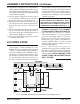
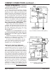
10. Attach blower assembly to rear of the back heat
shield with four Phillips head machine screws
from the hardware pack. Make sure to position
the ceramic gasket between the back heat shield
and the blower assembly.
11. After properly locating floor protector (fig 3)
to accommodate minimum stove clearances,
place stove in position on floor protector.
12. Route the power cord away from stove. Do not
allow the power cord to touch any hot surfaces.
Keep power cord at least 12” from stove sur-
faces.
13. Check to make sure that the bottom fire bricks
(#13) and ceramic fiber boards (parts #18 &
#19) above the air tube assembly (#6) have not
shifted during shipping or assembly.
14. Once stove is positioned, plug power cord into
a grounded 120v outlet.
ASSEMBLY INSTRUCTIONS continued…