THE SHILOH™ HIGH-EFFICIENCY WOODSTOVE EPA Certified (4.22 grams/hr) Model TR002B Owners Manual (Save These Instructions) Le manuel de langue français est disponible à www.vogelzang.com French language manual is available at www.vogelzang.com Report No. 235-S-01c-2 READ ALL INSTRUCTIONS CAREFULLY BEFORE INSTALLING OR OPERATING THIS STOVE. FAILURE TO FOLLOW INSTRUCTIONS MAY RESULT IN PROPERTY DAMAGE, BODILY INJURY, OR EVEN DEATH. REFER TO MARKINGS ON STOVE LABELS FOR ADDITIONAL INFORMATION.
SAFETY INSTRUCTIONS-Read All Instructions Carefully. 1. The installation of this stove must comply with your local building code rulings. Please observe the clearances to combustibles (see reference figures 10–12). Do not place fuel, furniture or any other objects within the clearance area. 2. Verify that the stove is properly assembled and installed before firing the stove for the first time.
SAFETY INSTRUCTIONS continued… 19. 20. 21. 22. 23. 24. 25. 26. 27. 28. 29. ing during the first 12 to 15 fires. Additional smoke and odor may be emitted from the light oils used in construction of the fire box. This should disappear after a short period of time and not occur again. Persons with lung conditions or owners of susceptible domestic pets (such as birds) should take prudent precautions. Open windows and doors as needed to clear smoke and/or odor.
TABLE OF CONTENTS SAFETY PRECAUTIONS................................................................................ 2 – 3 TOOLS AND MATERIALS REQUIRED FOR INSTALLATION............................. 5 ASSEMBLY INSTRUCTIONS ......................................................................... 5 – 6 LOCATING THE STOVE ....................................................................................... 7 Minimum Clearances ..........................................................................
ASSEMBLY INSTRUCTIONS NOTICE: Vogelzang International Corp. grants no warranty, stated or implied, for the installation or maintenance of your wood stove and assumes no responsibility of any incidental or consequential damages. TOOLS AND MATERIALS REQUIRED FOR INSTALLATION • • • • • • • • • • TOOLS Pencil 6 foot Folding Rule or Tape Measure Tin Snips Drill: Hand or Electric 1/8˝ dia.
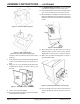
ASSEMBLY INSTRUCTIONS . . . continued 11. For Optional Blower Assembly, note the position of the blower opening in the rear of the stove. 12. Place blower gasket onto blower assembly (Figure 8) so as not to obstruct the air flow from the fan. 13. Mount the blower assembly to the back of the stove (Figure 9) aligning the fan opening to the opening in the back of the stove. Secure with four sheet metal screws. Figure 5 – Insert Ash Drawer Support. Figure 8 – Blower Option Figure 6 – Attach Pedestal Top.
LOCATING STOVE 1. The stove must be placed on solid concrete, solid masonry, or when installed on a combustible floor, on an UL 1618 Type 2 listed floor protector, such as Hy-C or Imperial Model UL 3648BK (US) or UL4048BK (CAN) or equivalent. Floor protector must be 1/2˝/13mm minimum thickness (“k” value = 0.84, R value = 0.59, see page 24 for calculation formulas) non-combustible material or equivalent.
LOCATING STOVE Failure to follow these minimum clearance requirements may result in an unsafe installation and could cause a fire. Installation of this stove must comply with the latest edition of NFPA 211 for reduced clearances and/ or your local building code rulings. Use whichever minimum dimensions are the LARGEST. 9. NEVER OPERATE THIS STOVE WITHOUT THE ASH CLEANOUT COVER IN PLACE OR WITH THE ASH DRAWER REMOVED – very dangerous operating conditions could result. 10. This stove meets U.S.
INSTALLATION INSTRUCTIONS FIREBRICK ASSEMBLY Firebrick extends the life of your stove and radiates heat more evenly. Check to see that all firebricks are in their correct positions and have not become misaligned during shipping or assembly. If removed for ease of locating stove, firebrick and ash dump cover must be replaced before firing. See diagrams, fig. 13a – 13c, for proper positioning.
CONNECTOR PIPE INSTALLATION NOTE: CONNECTOR PIPE IS NOT INCLUDED. TO PURCHASE, VISIT YOUR LOCAL HARDWARE, HOME OR BUILDING CENTER. SEE “LOCATING STOVE” PAGE 6 FOR ADDITIONAL SPECIFICATIONS. Connector pipe is used to make the connection from the final positioning of your stove to an approved chimney. Connector pipe is NOT included as part of the stove. Connector pipe must be 6˝/152mm diameter minimum of 24 MSG (minimum standard gauge) black or 26 MSG blue steel stove pipe.
CHIMNEY SIZING Today’s solid fuel heating appliances are much more efficient than those made in the past. Your heating appliance has been designed to provide the most efficient transfer of heat possible from the least amount of fuel. Controlled combustion is the key to optimum heating performance. Controlled combustion requires a flow of fresh air into the appliance, across the fuel and is finally exhausted up the chimney.
CHIMNEY CONNECTIONS If the connector stove pipe must go through a combustible wall before entering the masonry chimney, consult a qualified mason or chimney dealer. The installation must conform to local building and fire codes and latest edition of NFPA 211 (US) or CAN/CSA-B365 (CDN). If there is a cleanout opening in the base of the chimney, close it tightly. Chimney Minimum Height Requirements: (1) Overall Height – 15 ft./4.6m min. (2) Height above roof – 3 ft./91cm (3) Height above slope – 2 ft.
CHIMNEY CONNECTIONS continued … VENTING TO EXISTING FIREPLACE In some instances, people desire to convert an existing fireplace for stove use. Usually, safe connection to an existing masonry chimney requires more work than using a prefabricated chimney. The existing fireplace must be closed and sealed at the damper with high-temperature caulk, ceramic wool, or furnace cement. Prior to installation, clean and inspect the existing flue and smoke shelf.
CHIMNEY CONNECTIONS continued … least 8˝/203mm of liner must remain below the entry position. When locating the stove and stovepipe, all minimum clearances must be observed from combustible surfaces including mantels, combustible trim work, ceilings and walls. Positioning the center of the stove pipe entry into the chimney 24˝/61cm below the ceiling should insure proper clearance for a 6˝/152mm stovepipe. 2. Install a metal or fire clay (5/8˝/16mm minimum thickness) thimble.
CHIMNEY CONNECTOR SYSTEMS & CLEARANCES NOTE: IN CANADA, THE INSTALLATION MUST CONFORM TO CAN/CSA-B365 WHEN PASSING THROUGH COMBUSTIBLE CONSTRUCTION. A. Brick Masonry Minimum 3.5˝/89mm thick brick masonry all framed into combustible wall with a minimum of 12˝/305mm brick separation from clay liner to combustibles. The fireclay liner shall run from outer surface of brick wall to, but not beyond, the inner surface of chimney flue liner and shall be firmly cemented in place. B.
OPERATING INSTRUCTIONS THIS STOVE IS DESIGNED TO BURN WOOD FUEL ONLY! CAUTION: HOUSE FIRE HAZARDS • DO NOT STORE WOOD ON FLOOR PROTECTOR, UNDERNEATH STOVEPIPE OR ANYWHERE WITHIN MINIMUM CLEARANCES FROM COMBUSTIBLE SURFACES SPECIFIED FOR THIS STOVE. • OVER FIRING MAY CAUSE A HOUSE FIRE. YOU ARE OVER FIRING IF A UNIT OR CHIMNEY CONNECTOR GLOWS RED. OPERATING SAFETY PRECAUTIONS 1. NEVER OVER FIRE THIS STOVE BY BUILDING EXCESSIVELY HOT FIRES AS A HOUSE/ BUILDING FIRE MAY RESULT.
OPERATING continued … content. Some experimentation will initially be required to find that “sweet spot” where your stove performs best. The following will give you a starting point to find your optimum settings. When first loading fuel set the door air inlet control at the wide open position for at least 15–20 minutes. When the stove is working properly you should be able to observe secondary combustion flames above the fuel pieces in front of the secondary air tubes at the top of the firebox.
OPERATING continued . . . SERVICE HINTS 2. When adding fuel be careful not to hit or bump the ceramic baffle board located at the top of the firebox. 3. Add fuel being careful not to overload or over fire the stove. 4. When adding fuel be careful not to smother the fire. Do not build fires against glass and make sure the coal bed does not obstruct the air inlet. Do not add fuel to such a height or in such manner that it creates a hazard when opening the door. 5. Close the feed door and secure tightly. 6.
SERVICE HINTS continued . . . 5. Do not attempt to extend the burn time by using wet wood. Not only does burning wet wood rapidly build up creosote, but it reduces the heat output by up to 25 percent. 6. Burn the stove with the air inlet control wide open for 10-25 minutes every time fresh wood is loaded into the stove. Do not load more than ¼ to ½ of the fuel capacity at one time. Loading too much wood at once will cause excessive smoke which contains creosote.
SERVICE HINTS continued … to warm than manufactured chimneys on account of their greater structural mass. Chimneys that have a flue diameter larger than the stove outlet take more heat to warm, thus resulting in a faster cooling of the hot gases needed to build or maintain draft. 4. Chimney Installation and Maintenance Confirm that all four minimum chimney height requirements listed in the Chimney Connection section of the manual have been met.
SERVICE HINTS continued … DOOR GASKET REPLACEMENT CAUTION: DO NOT OPERATE A STOVE THAT IS MISSING DOOR GASKET MATERIAL. OVER FIRING AND UNSAFE OPERATING CONDITIONS MAY RESULT. PROCEDURE: 1. Ensure appliance is not in operation and is thoroughly cooled. 2. Remove old door gasket and clean channel. 3. Using an approved, high temperature gasket cement, apply a thin coat in bottom of channel. 4. Starting at hinge side of door, work gasket into channel around door unit, end butt and trim to length. 5.
ORDERING PARTS - TROO2B SHILOH™ STOVE When ordering missing or replacement parts, always give the Model Number of the stove, Part Number, and Part Description. Use the illustrations and part lists provided to identify parts. Contact us at 616-396-1911 to order parts. 1 2 5, 6 7 8, 9, 10 3 4 F-6S F-6 11 Fire Brick 15 NOTE: F6 Blower is Optional Equipment F-6G 16 12 33 33 14 34 29 31 32 30 35 Part No.
PARTS - TR001B DEFENDER HIGH-EFFICIENCY STOVE When ordering missing or replacement parts, always give the Model Number of the stove, Part Number, and Part Description. Use the illustrations and part lists provided to identify parts. Contact us at 616-396-1911 to order parts. 17 23 22 19 18 20 21 24 Part No. Description Qty. 2B-15 Door Assembly (complete) 1 2B-16 Handle Assembly (complete)..................... 1 2B-17 Hinge Pin ..................................................
FLOOR PROTECTOR MATERIAL CALCULATIONS This stove has been tested for and must be installed on a floor protector with the proper Thermal Resistance or R-value as stated in the installation instructions on page 6, “Locating Stove” step 1, of this manual. If the floor protector materials listed in the instructions are not available, materials with an equivalent R-value may be substituted.
CHIMNEY & STOVE MAINTENANCE LOG DATE OF SERVICE TR002B | 20120125.0 PERFORMED BY DESCRIPTION www.vogelzang.
This Vogelzang heating appliance is safe when installed properly and will provide you with years of service. However, always exercise good judgement when you are using this stove. You are dealing with FIRE! Fire is inherently dangerous and must be treated with respect.