
Instruction Manual


5
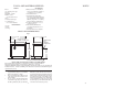
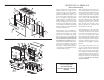
REPAIR PARTS LIST - MODEL VG820E
AUTOMATIC WOOD BURNING CIRCULATOR
INTERIOR
16
IMPORTANT
*Size the chimney to the ue outlet on the
stove. (6" outlet = 6" I.D. chimney)
*Avoid using elbows except as necessary
(they reduce dra ).
*Make sure all horizontal runs of connec-
tor pipe go up hill (1/4" elevation for each
horizontal foot).
CHIMNEY CONNECTION
DO NOT CONNECT THIS UNIT TO A
CHIMNEY FLUE SERVING ANOTHER
APPLIANCE.
Two basic types of chimneys are approved
for use with solid fuel: Factory-built and ma-
sonry. Factory-built chimney must comply
with UL103HT standard.
Do not expect your stove or furnace to create
dra . Dra is not a function of the appliance.
Dra is purely a function of the chimney.
Modern stoves and furnaces are much more
air-tight and e cient than those of the
past and, therefore require greater dra . A
minimum of .05, measured in water column
(gauges to measure chimney dra are readily
available at stove shops and are economical
to purchase or rent) is required for proper
dra ing to prevent back-pu ng, smoke
spillage, and to maximize performance.
Chimneys perform two functions - one of
which is apparent: e chimney provides
a means for exhausting smoke and ue
gases resulting from combustion of the fuel.
Secondarily, though, the chimney provides
Key Part No. Description Qty.
1 67859 Weldment, Base 1
2 22030 Shield, Second Heat (Included w/ 67859) 1
3 22110 Shield, Heat
(Included w/ 67859) 1
4 68619 Assy., Heat Jacket 1
5 88032 Gasket, Flue Collar 1
6 40246 Collar, Flue 1
7 22090 Curtain, Smoke 1
8 22171 Clip, Smoke Curtain 2
9 40075 Frame, Draft Damper 1
10 23476 Damper, Draft Control 1
11 25550 Pin, Draft Damper 1
12 83890 Clip, Push 1
13 40100 Liner, Front/Back 3
14 40076 Fire, Grate 2
15 40132 Retainer, Brick 2
16 89066 Firebrick (4.5” x 9” x 1.25”) 10
17 891940 Assy., Feed Door
(Complete) 1
- 40199 Feed Door -
Casting Only -
18 88033 Rope Gasket, 3/8” 3.75 ft.
19 891941 Assy., Ash Door
(Complete) 1
- 40289 Ash Door -
Casting Only -
20 88033 Rope Gasket, 3/8” 2.42 ft.
21 83872 Pin, Door -
Short 1
22 23441 Pin, Door -
Long 1
23 83102 Bolt, 1/4-20 x 1.25” CS, Slotted Hd. 2
24 40056 Wheel, Draft 2
25 83415 Nut, 1/4-20 Jam 2
26 25201 Shield, Flame 2
27 83250 Kep Nut, 1/4-20 4
28 40509 Handle, Door 2
29 89523 Handle, Drop Wood 1
30 22434 Latch, Door (2-Step) 1
31 83045 Washer, Flat 2
32 83273 Washer, Spacer 1
33 22108 Latch, Door
(Door Stop) 1
34 23474 Liner, Top 1
35 67444 Ash Pan 1
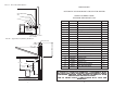
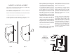
FIG. 6
Cathedral Ceiling - Chimney
Cap Mandatory
PIPE
FLOOR PROTECTOR
REFER TO CHIMNEY
MANUFACTURERS PARTS
AND INSTRUCTIONS
2 FT MIN.
10 FT.
3 FT.
MIN.
BAROMETRIC
DRAFT CONTROL
(OPTIONAL)
11 FT. MIN.
CHIMNEY CAP MANDATORY
DAMPER
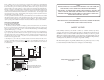
FIG. 5
PIPE
FLOOR PROTECTOR
REFER TO CHIMNEY
MANUFACTURERS PARTS
AND INSTRUCTIONS
2 FT MIN.
10 FT.
3 FT.
MIN.
BAROMETRIC
DRAFT CONTROL
(OPTIONAL)
11 FT. MIN.
CHIMNEY CAP MANDATORY
DAMPER
"Dra " which allows oxygen to be continu-
ously introduced into the appliance, so that
proper combustion is possible. As of April 1,
1987, all heaters and furnaces manufactured
by United States Stove Company should be
installed using a factory built chimney that
meets the "Type HT" requirement of UL 103
(when a factory - built chimney is used).
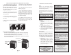
Your smoke pipe should be assembled in
such a way that the male section (crimped
end) of the pipe faces down. Attach each
of the sections to one another with three
equidistant metal screws. Seal with furnace
cement.
IN ORDER TO MAINTAIN WARRANTY, COMPONENTS MUST
BE REPLACED USING ORIGINAL MANUFACTURERS PARTS
PURCHASED THROUGH YOUR DEALER OR DIRECTLY
FROM THE APPLIANCE MANUFACTURER.
USE OF THIRD PARTY COMPONENTS WILL VOID THE
WARRANTY.