e Installation & Servicing Instructions THESE INSTRUCTIONS TO BE RETAINED BY USER
Contents Design principles and operating sequence 1.1 Principle components 1.2 Mode of operation (at reset) 1.3 Mode of operation (Heating) 1.4 Mode of operation (DHW) 1.5 Safety devices 1.6 Optional accessories Technical data 2.1 Central heating 2.2 Domestic hot water 2.3 Gas pressure 2.4 Expansion vessel 2.5 Dimensions 2.6 Clearances 2.7 Connections 2.8 Electrical 2.9 Flue details (concentric) 2.9A Flue details (twin pipes) 2.10 Efficiency 2.11 Pump duty 2.12 Emissions General requirements (UK) 3.
INTRODUCTION The Syntesi e appliance is a high-efficiency combination boiler with outputs to heating & DHW. The appliance – by design – incorporates electronic ignition, circulating pump, expansion vessel, safety valve, pressure gauge, and automatic by-pass. This appliance is not suitable for use with LPG. The Syntesi e is produced as room sealed, category I2H appliances, suitable for internal wall mounting applications only.
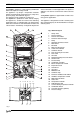
SECTION 1 1.1 1.2 1.3 1.4 2 DESIGN PRINCIPLE AND OPERATING SEQUENCE PRINCIPLE COMPONENTS ● A fully integrated electronic control board featuring electronic temperature control, anticycle control, pump over-run, self-diagnostic fault indicator, full air/gas modulation. ● Low-water-content, copper heat exchanger.
SECTION 2 TECHNICAL DATA 2.1 Central heating Heat input Max heat output 60/80°C (return & flow temp.) Max heat output 30/50°C (return & flow temp.) Min heat output 60/80°C (return & flow temp.) Min heat output 30/50°C (return & flow temp.) Minimum working pressure Maximum working pressure Minimum flow rate 2.2 Domestic hot water Maximum input Maximum output Minimum output Flow rate (35oC rise) Maximum inlet pressure Minimum inlet pressure Minimum flow rate 2.
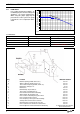
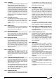
2.11 TECHNICAL DATA PUMP DUTY Fig. 3 shows the flow-rate available – after allowing for pressure loss through the appliance – for system requirements. When using this graph, apply only the pressure loss of the system. The graph is based on a 20°C temperature differential. 7 6,5 Water pressure (mbar) SECTION 2 6 5,5 Syn tesi 5 4,5 4 25 & 29 e 3,5 3 2,5 2 1,5 1 0,5 0 0 100 200 300 400 500 600 700 800 900 1000 1100 1200 1300 Litres Per Hour Fig. 3 2.
SECTION 3 GENERAL REQUIREMENTS (UK) This appliance must be installed by a competent person in accordance with the Gas Safety (Installation & Use) Regulations. 3.1 3.2 RELATED DOCUMENTS The installation of this boiler must be in accordance with the relevant requirements of the Gas Safety (Installation & Use) Regulations, the local building regulations, the current I.E.E.
WATER CIRCULATION Detailed recommendations are given in BS 5449 Part 1 and BS 6798. The following notes are for general guidance only. 3.6.1 PIPEWORK It is recommended that copper tubing to BS 2871 Part 1 is used in conjunction with soldered capillary joints. Where possible pipes should have a gradient to ensure air is carried naturally to air release points and that water flows naturally to drain cocks.
3.10 3.11 changers – is used to protect the boiler and system from the effects of corrosion and/or electrolytic action. The inhibitor must be administered in strict accordance with the manufacturers* instructions. TIMBER FRAMED BUILDINGS If the appliance is to be fitted in a timber framed building, it should be fitted in accordance with the Institute of Gas Engineers publication (IGE/ UP/7) ‘Guide for Gas Installations in Timber Frame Buildings’.
3A.6.1 PIPEWORK It is recommended that copper tubing be used in conjunction with soldered capillary joints. Where possible pipes should have a gradient to ensure air is carried naturally to air release points and that water flows naturally to drain cocks. Except where providing useful heat, pipes should be insulated to avoid heat loss and in particular to avoid the possibility of freezing.
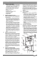
4.3 UNPACKING (see fig. 6) At the top of the carton pull both sides open – do not use a knife – unfold the rest of the carton from around the appliance, carefully remove all protective packaging from the appliance, and lay the accessories etc. to one side. Protective gloves should be used to lift the appliance, the appliance back-frame should be used for lifting points.
Reduction for additional bends Bend Reduction in maximum flue length for each bend 45° bend 0.5 metre 90° bend 1.0 metre Horizontal flue terminals and accessories Part No. Description Min-Max Length 0225720 Horizontal flue kit for use 1000mm with add. bends & NOTE Fit the internal trim to the flue assembly prior to connecting the flue pipe to the bend. You must ensure that the entire flue system is properly supported and connected.
Fig. 8 4.5.3 CONCENTRIC VERTICAL FLUE 60/100 mm The vertical flue terminal can be connected directly to the appliance flue outlet. Alternatively, an extension or bend can be connected to the appliance flue outlet if desired (see 4.4.2), however if additional bends are fitted, a reduction must be made to the maximum flue length (see table below). Reduction for bends Bend Reduction in maximum flue length for each bend 45° bend 0.5 metre 90° bend 1.
4.5.4 CONCENTRIC FLUE 80/125mm The Vokera 80/125mm concentric flue system enables greater flue lengths to be achieved compared to the standard 60/100mm concentric system. NOTE The 80/125mm-flue system must be used when installing the Syntesi 29 e. 80/125mm accessories Part No. 424 413 414 415 416 417 418 419 420 421 422 423 425 426 0225765 0225770 Description Condensing boiler adaptor Horizontal flue terminal kit Vertical flue terminal kit 87o Bend 45o Bend 0.25m extension 0.5m extension 1.
Appliance Dimension ‘X’ Dimension ‘Y’ Syntesi 25 e 215mm 400mm Syntesi 29 e 215mm 450mm 4.5.4.2 FITTING THE HORIZONTAL TERMINAL The horizontal terminal can be installed either from the internal or external wall. Ensure the terminal is facing the correct way up and extends past the finished external wall by the correct distance (see fig. 15). Once the terminal has been inserted through the wall the internal trim should be fitted.
4.5.6 TWIN FLUE SYSTEM The Vokera twin flue system enables greater flue distances to be achieved (see 4.4.2) than that of a concentric flue system. It can be used for horizontal or vertical applications, however the twin flue system must be converted to the dedicated concentric flue kit for termination. It is essential that the installation of the twin flue system be carried out in strict accordance with these instructions.
1-deg. = 17mm 1.0-metre Fig. 20 4.5.6.2 HORIZONTAL TERMINATION (see fig. 20) The twin flue system must be converted to the dedicated concentric flue kit for termination. ● The horizontal terminal is supplied with a builtin converter box and cannot be shortened. ● A 130mm hole is required for the passage of the concentric terminal through the wall. ● The air inlet pipe must always be level with or below, that of the exhaust pipe.
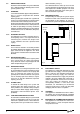
Hot water Outlet Cold water Inlet Stopcock/filling valve C/H flow valve Filling Loop Fig. 22 16 CONNECTING THE GAS AND WATER The appliance is supplied with a fixing jig that includes service valves (fig. 22). The service valves are of the compression type. The accessories pack contains sealing washers etc, for use with the service valves. When connecting pipe work to the valves, tighten the compression end first then insert the sealing washers before tightening the valve to the appliance.
Connect a discharge pipe to the fixing jig connection and tighten. The discharge pipe must have a continuous fall away from the appliance to outside and allow any water to drain away thereby eliminating the possibility of freezing. The discharge pipe must terminate in a position where any water – possibly boiling – discharges safely without causing damage or injury, but is still visible. 4.6.
Do not remove the link wire (between TA & Spare) unless additional external controls are to be fitted (see section 8). remove the clock aperture plate from the appliance ● remove the push-out blanking disc from the clock aperture plate (fig. 25) ● secure the clock to the aperture plate using the screws provided with the clock (fig.
SECTION 5 COMMISSIONING 5.1 GAS SUPPLY INSTALLATION Inspect the entire installation including the gas meter, test for soundness and purge. Refer to BS 6891 for specific instruction. 5.2 THE HEATING SYSTEM The appliance contains components that may become damaged or rendered inoperable by oils and/or debris that are residual from the installation of the system, consequently it is essential that the system be flushed in accordance with the following instructions.
5.11 Outlet test-point Protective cap Syntesi 25 8-litre (Orange) Fitted 9-litre (Blue) Spare Syntesi 29 9-litre (Orange) Spare 10-litre (Blue) Fitted Inlet test-point FINAL FLUSHING OF THE HEATING SYSTEM The system shall be flushed in accordance with BS 7593. If a cleanser is to be used, it shall be from a reputable manufacturer* and shall be administered in strict accordance with the manufacturers instructions.
5.13 INSTRUCTING THE USER Hand over all documentation supplied with this appliance – including these instructions – and explain the importance of keeping them in a safe place. Explain to the user how to isolate the appliance from the gas, water, and electricity supplies, and the locations of all drain points. Show the user how to operate the appliance and any associated controls correctly.
Fig. 28 6.6 SAFETY VALVE (see fig. 29) Carry out component removal procedure as described in 6.4. Disconnect the outlet pipe from the safety valve, remove safety valve locking screw (1) from the heating manifold. Replace in the reverse order. Fig.30 6.9 PRESSURE GAUGE (see fig. 31) Carry out component removal procedure as described in 6.4.
Fig. 32 6.11 Fig. 34 HIGH LIMIT THERMOSTAT (see fig. 33) Carry out component removal procedure as described in 6.4. Unclip and remove the air chamber cover. Pull off electrical connections from the high limit thermostat (2), slacken and remove retaining screws (3). Replace in reverse order. NOTE Ensure that any replacement PCB has the correct ‘Jumper Tag’ configuration (see section 8). 6.13 GAS VALVE (see fig. 35) Carry out component removal procedure as described in 6.4.
6.14 INTEGRAL TIME SWITCH (if fitted) Carry out component removal procedure as described in 6.4. Locate and remove the terminal cover and securing screws (2), locate and remove the time clock retaining screws, remove time clock. Disconnect wiring after carefully taking note of all electrical connections. Replace in the reverse order. 6.15 ELECTRODE, BURNER THERMOSTAT, BURNER & INJECTORS (see fig. 36) Carry out component removal procedure as described in 6.4. Unclip and remove the air chamber cover (2).
6.16 FLUE FAN (see fig. 36 & 38) Carry out component removal procedure as described in 6.4. Fig. 36: unclip and remove the air chamber cover, gently pull the cover towards you before lifting and disengaging (2). Locate and remove the six screws that secure the front combustion cover, then remove the cover (3). Fig. 38: disconnect the electrical connections and silicone tubes (10) attached to the fan, noting their positions.
6.18 AIR PRESSURE SWITCH (see fig. 38) Carry out component removal procedure as described in 6.4. Fig. 36: unclip and remove the air chamber cover, gently pull the cover towards you before lifting and disengaging (2). Fig. 38: locate and remove the two screws (6) holding the air pressure switch to the air chamber. Disconnect the electrical connections and silicone tubes (10) attached to the air pressure switch, noting their positions. Replace in the reverse order.
6.24 SECONDARY THERMISTOR (see fig. 44) Carry out component removal procedure as described i 6.4. Pull back the protective cover from the thermistor and disconnect the electrical plug. Using a 13mm spanner slacken and remove the thermistor and sealing washer from the DHW heat exchanger manifold. Replace in the reverse order. Fig. 46 6.27 Fig. 44 6.25 AUTOMATIC BYPASS (see fig. 45) Carry out component removal procedure as described in 6.4.
6.28 LATENT HEAT COLLECTOR fig’s. 48 & 49 Carry out component removal procedure as described in 6.4. Remove the flue hood and fan assembly as detailed in 6.16. Disconnect the condense sensor wire from the sensor. Fig. 48: disconnect and remove the inlet (1), outlet (3) and condense pipes (2) from the collector. Fig. 49: unscrew and remove the 3 screws (1) that secure the collector to the air chamber and disconnect the collector (2) from the flue connection.
SECTION 7 7.1 CHECKS, ADJUSTMENTS AND FAULT FINDING CHECKING APPLIANCE OPERATION When carrying out any repairs or servicing to the appliance, the relevant commissioning procedure must be undertaken to ensure the continued safe operation of the appliance. Particular attention should be made to ensure gas soundness, water soundness and the electrical integrity of the appliance. 7.2 APPLIANCE MODE OF OPERATION NOTE: there must be sufficient system water pressure (min. 0.
NOTES The timer delay can be de-activated by the insertion of a ‘jumper’ on the PCB or by isolating the appliance from the electrical supply for 30 seconds. Any DHW request will always have priority over the heating request. When the request for heating has been satisfied, the appliance pump and fan may continue to circulate to dissipate any residual heat within the appliance. 7.2.6 7.3 7.3.
● ● ● Light the boiler as described in 5.7 and press the ‘CO mode’ button once. The boiler will now enter the combustion analysis mode (CO mode) for a period of 15 minutes. During this time it will remain on full gas and ‘CO’ will be displayed on the LED display. Once the flue gas analysis has been made, press the ‘CO mode’ to resume normal operation. Fault code 01 02 03 04 Protecting cap Air analysis outlet 7.
or a supply fault, consult the local electricity supplier for advice. 7.7.5 7.8 7.9 RESISTANCE TO EARTH CHECK Isolate the appliance from the electrical supply, and using a suitable multi-meter carry out a resistance test. Connect test leads between the Live & Earth connections at the appliance terminal strip (fig.24). If the meter reads other than infinity there is a fault that must be isolated, carry out a detailed continuity check to identify the location of the fault.
VOKERA LINEA PLUS AG START Rev. 1 08/03/2000 TEST A : CHECKING OPERATION OF ELECTRONIC CONTROL BOARD AT START UP IS THE 3 WAY VALVE IN DHW POSITION? NO NO MAINS ON 3 WAY VALVE BETWEEN TERMINALS M11.1 & M11.3 ON PCB YES NO TURN ON HOT TAP A2 CHECK &/OR REPLACE WIRING OR CONNECTIONS AND 3 WAY VALVE PUMP RUNNING BETWEEN TERMINALS M5.5 & M5.
A1 IS THERE 24 Vdc BETWEEN TERMINALS M5.3 AND M3.3 ON PCB NO YES REPLACE THE CONTROL BOARD IS THERE 24 Vdc NO BETWEEN TERMINALS M5.3 ON PCB & WHITE WIRE ON HIGH LIMIT THERMOSTAT CHECK WIRING AND CONNECTIONS YES IS THERE 24 Vdc NO BETWEEN TERMINALS M5.3 ON PCB & RED WIRE ON HIGH LIMIT THERMOSTAT YES RESET THE HIGH LIMIT THERMOSTAT IS THERE 24 Vdc BETWEEN TERMINALS M5.3 AND M3.
A2 5 Vdc BETWEEN TERMINALS M2.1 & M2.2 ON DISPLAY BOARD YES IS RED LED FLASHING FAULT CODE SHOWING 5 Vdc BETWEEN TERMINALS M9.1 & M9.2 ON CONTROL BOARD NO YES YES CHECK AND/OR REPLACE WIRING OR CONNECTIONS WITH DISPLAY BOARD NO MAINS PRESENT BETWEEN M16.L & M16.
VOKERA LINEA PLUS AG START Rev. 1 08/03/2000 TEST B : CHECK CONTROL IN DHW MODE TURN MODE SELECTOR SWITCH TO DHW. DHW STAT AT MAX. TURN ON TAP NO CHECK BOILER STARTUP: TEST A DOES BURNER LIGHT YES IS THERE A VOLTAGE >4 Vdc BETWEEN TERMINALS M3.10 & M3.11 ON PCB NO IS FAN ON? YES YES IS D.A.P.S. OK? NO CHECK FAN, WIRING AND CONNECTIONS, DIFFERENTIAL ANALOG PRESSURE SWITCH AND CONTROL BOARD NO YES TURN DHW THERMOSTAT AT MIN. DO BURNER AND FAN SWITCH OFF YES TURN DHW THERMOSTAT AT MAX.
VOKERA LINEA PLUS AG START Rev. 1 08/03/2000 SWITCH ON BOILER AND SELECT MODE TO WINTER C/H THERMOSTAT AT MAX. TEST C: CHECK CONTROL IN C/H MODE MAKE A LINK BETWEEN PIN M16.TA AND M16.TA ON CONTROL BOARD YES DOES BURNER LIGHT IS THE 3 WAY VALVE ON CH POSITION? NO YES NO CHECK BOILER STARTUP TEST A MAINS PRESENT BETWEEN M11.1 & M11.2 ON CONTROL BOARD YES IS THERE A VOLTAGE >4 Vdc BETWEEN TERMINALS M3.10 & M3.11 ON PCB CHECK &/OR REPLACE 3 WAY VALVE IS FAN ON? YES IS D.A.P.S.
A SPARK AT ELECTRODE NO IS THERE MAIN BETWEEN TERMINALS M14.1 & M14.2 ON PCB YES IGNITION NO YES NO IS THERE MAIN BETWEEN TERMINALS L & N ON IGNITION CONTROL LOCKOUT AFTER IGNITION YES END YES NO YES CHECK SENSING ELECTRODE AND LEAD YES NO CHECK WIRING AND CONNECTIONS CHECK SPARK ELECTRODE AND LEAD OR REPLACE IGNITION CONTROL SENSING ELECTRODE AND LEAD OK REPLACE IGNITION CONTROL IS THERE 0 Vdc NO BETWEEN TERMINALS M5.3 & M5.
A3 A4 FAULT CODE SHOWING 03 DOES THE FLOW SWITCH PIN OPERATE YES NO YES FAULT CODE SHOWING 04 NO YES REPLACE CONTROL BOARD DO THE BOILER FLOW SWITCH OPERATE NO CHECK AND/OR REPLACE THE DIAPHRAGM. CHECK THE CORRECT WATER DP CHECK THE WATER CIRCUIT.
C DO BURNER AND FAN SWITCH ON YES NO NO WAIT 3 MIN. IS TIMER JUMPER ON YES REPLACE CONTROL BOARD DO BURNER AND FAN SWITCH ON WAIT WATER FLOW TEMPERATURE < 80 ˚C YES REMOVE JUMPER YES RESTART THE TEST NO IS THERE A VOLTAGE < 1 Vdc IS WATER FLOW TEMPERATURE >80 ˚C YES NO BETWEEN TERMINALS M3.10 & M3.11 ON PCB IS THERE A VOLTAGE >4 Vdc NO BETWEEN TERMINALS M3.10 & M3.11 ON PCB REPLACE CONTROL BOARD YES IS TIMER JUMPER ON JP9 YES NO REMOVE JUMPER REMOVE THE LINK BETWEEN PIN M16.
SECTION 8 8.1 WIRING DIAGRAMS EXTERNAL WIRING The appliance comes with a factory fitted link to allow basic operation of the boiler via the mode selector switch. If external controls are to be added to the system, they must be connected to the appliance as shown in the following diagrams. For advice on controls that are not featured in this book, please contact Vokera technical on 0870 333 0520.
Fig.
FUNCTIONAL DIAGRAM NOTE: L-N-E CONNECTION IS ADVISABLE CONTROL SWITCHING OF TIME CLOCK AND ROOM THERMOSTAT IS 230 V.a.c. R.T. TS H G.V. C.S. D.H.W.F.S. P.S. H.L.T. H.T. D.H.W.T. MOD F P 3W S.S.E. OPE B.C.B. (ACF02X) B.E.B. S.B.
44 CONTROL SWITCHING OF TIME CLOCK AND ROOM THERMOSTAT IS 230 V.a.c.
SECTION 9 EXPLODED DIAGRAMS 31 90 1 362 226 18 16 17 20 48 19 326 26 38 51 43 400 50 401 52 53 12 402 39 40 POS.
40 1 201 201 285 26 202 292 37 4 248 292 2 24 351 201 41 328 200 7 31 9 3 351 328 351 22 328 10 365 16 19 11 18 353 202 17 366 353 30 64 366 28 62 61 27 34 35 400 POS.
388 500 45 393 1 47 394 395 201 400 396 200 2 285 200 394 200 202 8 287 277 9 200 49 7 371 48 200 370 27 50 26 398 200 25 2 3 5 370 28 290 288 372 6 40 11 288 4 289 10 POS.
2 21 2 21 9 4 3 1 332 12 5 17 200 18 19 13 10 351 16 328 200 400 500 14 501 15 401 POS. 1 2 3 4 5 9 10 12 13 14 15 16 17 18 19 21 200 328 332 351 400 401 500 501 DESCRIPTION Air box bottom Ambidx air box side Air box clip Burner Spark electrode NG plate Gas valve solenoid Gas pipe Gas valve Gas pipe Gas cock Air box cover Washer Glass Glass flange Washer Washer Clip Thermostat Nut Gas valve cable Gas valve coil cable N.G.
23 25 19 20 10 16 295 7 300 1 4 2 3 3 POS.
Cod. 10026409 - 27/04 - Ed. 1 energizing home heating Vokèra Ltd. 4th Floor, Catherine House, Boundary Way, Hemel Hempstead, Herts, HP2 7RP Email: enquiries@vokera.co.uk Web: www.vokera.co.uk Sales, Technical Advice, General Enquiries - Tel: 0870 333 0520 Fax: 01442 281403 After Sales Service - Tel: 0870 333 0220 Vokèra Ireland West Court, Callan, Co Kilkenny Tel: 05677 55057 Fax: 05677 55060 Vokèra Ltd. reserve the right to change the specifications without prior notice.