
Repair Manual


9.12 Braking system
withdraw the lines so that they are just clear of
the regulator. Tape the ends of the brake lines
to prevent entry of dust and dirt.
6 Unscrew the mounting bolts and withdraw
the regulator from under the car.
Refitting
7 Before refitting the regulator check that the
brake line apertures and sealing surfaces are
clean.
8 Locate the regulator on the underbody,
insert the bolts and tighten securely.
9 Remove the tape and wipe clean the ends
of the hydraulic lines then insert them into
their correct positions and tighten the union
nuts. To ensure that the nuts are not cross-
threaded, initially tighten them by hand only.
10 Hook the spring onto the regulator and
adjustment roller.
11 Remove the polythene from the master
cylinder then bleed the complete hydraulic
circuit as described in Section 2.
12
Lower the car to the ground.
13 The initial operation of the regulator can
be checked as follows Have an assistant
depress the brake pedal rapidly and check
that the regulator lever moves at the same
time.
Adjustment
14 Checking and adjustment of the regulator
is best left to a WV garage as special pressure
gauges and spring tensioning tools are
required. Adjustment is made by varying the
spring tension, but this must be carried out by
the garage.
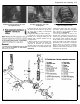
1 The stop-light switch is located either on
the pedal bracket or on the master cylinder.
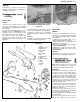
18.2 Stoplight switch location
on the pedal bracket
Pedal bracket-mounted type
Removal
2 Reach up behind the facia and disconnect
the wiring connector from the switch on the
‘pedal bracket (see illustration).
3 Twist the switch through 90° and release it
from the mounting bracket. Note: The switch
for RHD and LHD models is different.
Refitting
4 Prior to installation, fully extend the
stoplight switch plunger.
5 Fully depress and hold the brake pedal,
then manoeuvre the switch into position.
Secure the switch in position by twisting it
through 90° and release the brake pedal.
6 Reconnect the wiring connector, and check
the operation of the stop-lights. The stop-
lights should illuminate after the brake pedal
has travelled about 5 mm. If the switch is not
functioning correctly, it is faulty and must be
renewed; no adjustment is possible.
Master cylinder-mounted type
Removal
7 Have ready a suitable plastic or rubber
bung which will be a close fit in the switch
aperture in the master cylinder. Place some
cloth rags beneath the switch.
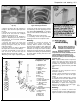
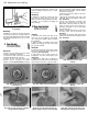
19.3 Unscrewing the handbrake warning
light switch mounting screw
8 Disconnect the wiring from the switch.
Loosen and unscrew the switch until it is on
its last threads, then quickly unscrew and
remove it and the washer, and fit the bung.
Refitting
9 Fit a new washer onto the switch.
10 Remove the bung and fit the switch as
quickly as possible, then tighten it securely.
11 Wipe clean the exterior of the master
cylinder and reconnect the wiring.
12 Bleed the complete hydraulic circuit as
described in Section 2.
Removal
1 Remove the plastic cover from the
handbrake lever and fully apply the lever.
2 Pull back the carpet, then disconnect the
wiring from the warning light switch which is
mounted on a bracket on the floor.
3 Unscrew the mounting screw and lift the
switch out (see illustration).
Refitting
4 Refitting is a reversal of removal.