
Repair Manual


Engine removal and overhaul procedures 2B.7
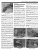
4.40 Measure the diameters of the valve
stems at several points along their lengths
using a micrometer
41
Check the overall length of each valve and
compare the measurements with the figure in
the Specifications.
42 The valve heads should not be cracked,
badly pitted or charred. Note that light pitting
of the valve head can be rectified by lapping-
in the valves during reassembly, as described
later in this Section.
43 Check that the valve stem end face is free
from excessive pitting or indentation; this
would be caused by defective hydraulic
tappets.
44 Place the valves in a V - block and using a
DTI gauge, measure the runout at the valve
head. A maximum figure is not quoted by the
manufacturer, but the valve should be
renewed if the runout appears excessive.
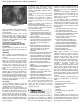
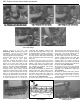
45 Insert each valve into its respective guide
in the cylinder head and set up a DTI gauge
against the edge of the valve head. With the
valve end face flush with the top of the valve
guide , measure the maximum side to side
deflection of the valve in its guide (see
illustration). If the measurement is out of
tolerance, the valve and valve guide should be
renewed as a pair. Note: Valve guides are an
interference fit in the cylinder head and their
removal requires access to a hydraulic press.
For this reason, it would be wise to entrust the
job to an engineering workshop or head
rebuilding specialist.
46 Using vernier callipers, measure the free
length of each of the valve springs. As a
manufacturer’s figure is not quoted, the only
way to check the length of the springs is by
comparison with a new component. Note that
valve springs are usually renewed during a
major engine overhaul.
47 Stand each spring on its end on a flat
surface, against an engineers square. Check
the squareness of the spring visually; if it
appears distorted, renew the spring.
48 Measuring valve spring pre-load involves
compressing the valve by applying a specified
weight and measuring the reduction in length.
This may be a difficult operation to conduct in
the home workshop, so it would be wise to
approach your local garage or engineering
workshop for assistance. Weakened valve
springs will at best, increase engine running
noise and at worst, cause poor compression,
so defective items should be renewed.
Reassembly
Caution: Unless all new components are
to be used maintain groups when refitting
valve train components - do not mix
components between cylinders and
ensure that components are refitted in
their original positions.
49 To achieve a gas tight seal between the
valves and their seats, it will be necessary to
grind, or ‘lap’, the valves in. To complete this
process you will need a quantity of
fine/coarse grinding paste and a grinding tool
- this can either be of the dowel and rubber
sucker type, or the automatic type which are
driven by a rotary power tool.
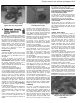
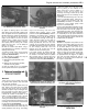
50 Smear a small quantity of fine grinding
paste on the sealing face of the valve head.
Turn the cylinder head over so that the
combustion chambers are facing upwards
and insert the valve into the correct guide.
Attach the grinding tool to the valve head and
using a backward/forward rotary action, grind
the valve head into its seat. Periodically lift the
valve and rotate it to redistribute the grinding
paste (see illustration).
51 Continue this process until the contact
between valve and seat produces an
unbroken, matt grey ring of uniform width, on
both faces. Repeat the operation for the
remaining valves.
52 If the valves and seats are so badly pitted
that coarse grinding paste must be used,
check first that there is enough material left on
both components to make this operation
worthwhile
- if too little material is left
remaining, the valve stems may protrude too
far above their guides, impeding the correct
operation of the hydraulic tappets. Refer to a
machine shop or cylinder head rebuilding
specialist for advice.
53 Assuming the repair is feasible, work as
described in the previous paragraph but use
the coarse grinding paste initially, to achieve a
dull finish on the valve face and seat. Then,
wash off coarse paste with solvent and repeat
the process using fine grinding paste to obtain
the correct finish.
54 When all the valves have been ground in,
remove all traces of grinding paste from the
cylinder head and valves with solvent and
allow them to dry completely.
55 Turn the head over and place it on a
stand, or wooden blocks. Leave enough
room underneath to allow the valves to be
inserted.
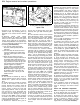
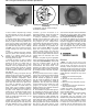
56 Working on one valve at a time, lubricate
the valve stem with clean engine oil and insert
it into the guide. Fit one of the protective
plastic sleeves supplied with the new valve
stem oil seals over the valve end face - this
will protect the oil seal whilst it is being fitted
(see illustrations).
57 Dip a new valve stem seal in clean engine
oil and carefully push it over the valve and
onto the top of the valve guide - take care not
to damage the stem seal as it passes over the
valve end face. Use a suitable long reach
socket to press it firmly into position (see
illustration).
58 Locate the valve spring(s) over the valve
stem. Where a lower spring seat is fitted,
ensure that the springs locate squarely on the
4.45 Measuring the deflection
of a valve in its guide
4.50 Grinding in a valve
4.56a Fitting a valve
into its guide
4.56b Fitting a protective plastic sleeve
over the valve end face