Service. The Passat ‘97 The Presentation Construction and operation Self Study Programme Only for internal use. © VOLKSWAGEN AG, Wolfsburg All rights reserved. Subject to modification. 640.2810.10.00 Technical Status: 09/96 ` Printed on chlorine-free bleached paper.
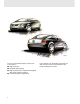
191/01 The most remarkable features of the new Passat are its: l High economy l Dynamic body styling l High-quality interior equipment designed with great attention to detail l Pioneering safety engineering 2 In this booklet, we would like to provide you with an initial overview showing how we justify making these claims.
Page The Passat ‘97 04 Environmental Protection and Recycling 08 Body 10 Vehicle Safety 15 Engines and Gearboxes 19 Running Gear 26 Brakes 29 Steering 30 Electrics 31 Extended Systems 36 Important ! / Note New The Self Study Programme is not a Workshop Manual. Please refer to the relevant Service Literature for all inspection, adjustment and repair instructions.
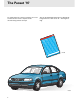
The Passat ‘97 To avoid confusion, concise examples are used to illustrate the various aspects of this all-embracing vehicle concept. You can find detailed information in Self Study Programme No. 192 Passat ‘97 – The Engineering. 192 Serv ice.
Dimensions and Weights 2707 mm 4675 mm 191/71 1740 mm Weights Track widths front rear 1498 1500 mm mm Unladen weight Max. permissible weight appr. 1200 kg appr.
The Passat ‘97 The Platform - an Advantage for Workshops The term “platform” is frequently used in publications although its fundamental meaning is not explained. The result of this is that people are often unsure of what the term “platform” implies. The vehicle consists of a) the platform and b) the body. Design and vehicle characteristics dictate what form the body takes. In the eyes of the customer, the body characterises the styling of the vehicle as a whole.
Platform The platform comprises both common parts and system parts. Common parts System parts e.g. sliding sunroof, steel rim e.g. seat Common parts may only be used in platform vehicles without change. They do not influence the design of the vehicle. Some system parts are identical. They have to be adapted since they are the interface between the platform and body. System part Common part Adapted part Frame Vehicle-specific seat upholstery, seat cover, etc.
Environmental Protection and Recycling The concept of eco-friendliness was pursued consistently throughout development of the new Passat. We would now like to show you some aspects of this topic which are also of interest to workshops. Recycling Not least the recycling requirements present workshops with problems such as identifying, presorting and storing materials and waste operating media.
Solvents Even during production, every effort is made to keep environmental pollution to a minimum. To achieve this, the following measures were taken: l Full galvanisation means much less wax and PVC underseal l Water-dilutable paints including water-based clear coat l Stringent requirements for materials ensure lower emissions in the vehicle interior Energy + Resources Raw materials and energy are in limited supply on the planet Earth. We must use them sparingly.
Body The following will be of interest to you: l l l l The Passat in the wind tunnel Fully galvanised body Greater body rigidity Use of high-strength steel parts l Strategy of using common platform for body parts l Ease of repair demonstrated using door module as example l Rear collision demonstrated using bumper as example The Passat in the Wind Tunnel As you can see from the streamlines, the body of the new Passat is very aerodynamic. No turbulence, which increases aerodynamic drag, occurs.
Fully-galvanised Body For the first time, the Passat has a fully galvanised body which comes with an 11-year anticorrosion perforation warranty. The drawing below shows you the parts which are hot-dip galvanised and those which are electrolytically galvanised. Electrolytically galvanised Surface patterns, which are also visible after painting, emerge during the hot-dip galvanisation process. That is why the outer skin of the body is electrolytically galvanised to produce a smooth finish.
Body Stability and Structure The Passat leads its class in terms of torsional rigidity. This was achieved by using: l high-strength panels l different panel thicknesses l improved adhesive bonding techniques (e.g. adhesive joints) Adhesive joints increase rigidity and leakproofing while minimising noise levels.
High-strength Panels The Rear Bumpers High-strength panels are used to produce a body with greater stability and strength and therefore to provide more safety for the vehicle occupants. They also substantially reduce the weight of the body-in-white. As you can see, the high-strength steel components in the front section of the vehicle create a cage-type structure to protect the vehicle occupants. The wings are also manufactured from highstrength steel.
Body Body Platform The floorpan assembly, side members and luggage compartment floor assembly were adopted from the Audi A4 as a platform. To enhance ride comfort for rear-seat passengers, a steel floor plate 86 mmwide was inserted.
Vehicle Safety The following features will be of interest to you: l Active and passive safety l Driver, front passenger and side airbags as standard l ABS as standard l New seat belt tensioner with force limiter l The Passat already complies with the new European standard for crashworthiness l Inside door panels with pelvis paddings l Door module with enclosed subframe As you will no doubt already know, we make a distinction between active and passive safety.
Vehicle Safety Crashworthiness The new Passat offers the driver and front passenger more safety, particularly during a side impact. The inside door panel, which is fitted complete with built-in door fittings, is bolted to the door. To protect the occupants, the inside door panel has an enclosed surface to prevent intrusion of the built-in door fittings into the interior of the vehicle.
Airbag Systems In addition to the driver and front passenger airbags, the Passat is equipped with side airbags as standard. Depending on the side and angle of impact, only the airbags in the immediate vicinity of the danger zone are inflated. The driver and front passenger airbags, which have filling volumes of roughly 65 ltr. and 120 ltr. respectively, conform to the new international-standard airbag sizes. The volume of the standard side airbag is roughly 12 litres.
Vehicle Safety The Seat Belt Tensioner The pyrotechnical seat belt tensioner, together with the “belt fastened” sensor and belt force limiter, are combined in a single assembly. This compact design greatly simplifies replacement. The “belt fastened” sensor prevents the seat belt tensioner from being activated when the seat belt is not worn.
Engines and Gearboxes In addition to the six tried and tested engines listed below, the new VR5 unit will also be mounted in the Passat. 1.6-ltr. Engine AHL Displacement Compression ratio Max. torque Max. power output Engine management Fuel 1595 cc 10.3 : 1 140 Nm at 3800 rpm 74 kW at 5300 rpm Simos 2 95 RON unleaded premium This engine is also used in the Audi A3. It is mounted in the Passat without a twin-path intake manifold. 191/85 1.8-ltr. 5V Engine ADR Displacement Compression ratio Max.
Engines and Gearboxes 1.8-ltr. 5V Turbo Engine AEB Displacement Compression ratio Max. torque Max. power output Engine management Fuel 1781cc 9.3 : 1 210 Nm at 1750-4600 rpm 110 kW at 5700 rpm Motronic M 3.8.2 95 RON unleaded premium This engine is also used in the Audi A4. 191/31 2.8-ltr. V6 Engine ACK Displacement Compression ratio Max. torque Max. power output Engine management Fuel 2771cc 10.3 : 1 280 Nm at 3200 rpm 142 kW at 6000 rpm Motronic M 3.8.
2.3-ltr. VR5 Engine AGZ The new VR5 engine has a displacement of 2.3 litres. It is derived from the VR6 engine and is designed for in-line or transverse mounting. Power output is 110 kW. 191/53 The engineering of the VR5 engine is explained in a separate Self Study Programme.
Engines and Gearboxes 1.9-ltr. TDI Engine AHU Displacement Compression ratio Max. torque Max. power output Fuel Mixture preparation 1896 cc 19.5 : 1 202 Nm at 1900 rpm 66 kW at 4000 rpm 45 CN diesel Direct injection with electronically controlled distributor injection pump 191/28 1.9-ltr. TDI Engine AFN Displacement Compression ratio Max. torque Max. power output Fuel Mixture preparation 1896 cc 19.
Range of Engines and Gearboxes Manual gearbox 012/01W Engines 1.6-ltr. 74kW Automatic gearbox 01N 1.8-ltr. 5V 92kW 1.8-ltr. 5V turbo 110kW 01V 2.3-ltr. VR5 110kW 1.9-ltr. TDI 66kW 1.9-ltr. TDI 81kW 01A 2.8-ltr.
Engines and Gearboxes 5-speed Manual Gearbox 012/01W The 012/01W is a manual gearbox as used in the Audi A4. This gearbox has a magnesium housing for installation in the 1.6-ltr./74kW aluminium engine block. 191/34 5-speed Manual Gearbox 01A The 01A is the manual gearbox for four-wheel drive vehicles as used in the Audi A4.
4-speed Automatic Gearbox 01N The 01N is also installed in the Audi A6, for example. You can find detailed information on this gearbox in Self Study Programe No. 172. 191/36 5-speed Automatic Gearbox 01V You will also be familiar with the 01V from the Audi A4. It is equipped with Tiptronic control as standard. You can find detailed information on this gearbox in Self Study Programme No. 180.
Running Gear In addition to the four-link front suspension, we will show you on the following pages the newly developed torsion beam rear suspension as well as the new double-wishbone rear suspension unique to Syncro models. The Four-link Front Suspension The four-link front suspension is standard in all front- and four-wheel drive vehicles. In the case of vehicles with tripoid joints, these joints can be repaired.
The Torsion Beam Rear Suspension Advantages of torsion beam rear suspension: - - Larger through-loading width due to the fact that the coil springs and shock absorbers are kept physically apart Use of single-tube dampers Downward-facing V-section of axle beam Self-aligning twin-grooved oblique ball bearings act as wheel bearings Single-tube damper Coil spring 191/55 27
Running Gear The Double-wishbone Rear Suspension The double-wishbone rear suspension was developed in order to provide a through-loading width of over 1000 mm. 191/54 Engine power is transmitted to all four wheels by a Torsen differential.
Brakes The Passat is equipped with the Bosch 5.3 antilock braking system as standard. Two different sizes of brake disc are available for the front axle. The rear suspensions also have disc brakes as standard. Disc brakes, front Disc brakes, rear 191/14 191/16 280 x 22 mm brake disc 282.5 x 25 mm brake disc Rear brake caliper The front disc brakes are vented. The smaller disc diameter is based on a smaller vehicle mass and lower power output This disc brake is vented and larger in size.
Steering Height and Reach Adjustment of Steering Column The Passat is equipped with power steering. The steering column can be adjusted manually 50 mm fore and aft and 28 mm for height. A damper element located above the double universal joint prevents vibrations and noise from being transmitted to the body. A clamped connection links the steering column to the power steering gear. The steering column is attached to the body by a mounting pedestal with sliding guide.
Electrics The following features will be of interest to you: l Gas discharge headlights l Washer jets l Decentralised vehicle electrical system l Dash panel insert Decentralised Vehicle Electrical System Advantages: The main feature of the decentralised vehicle electrical system is that the central electrics are subdivided into separate connector stations, relay carriers and fuse carriers. These submodules are arranged locally.
Electrics Dash panel insert The following features will be of interest to you: l Electronic immobiliser integrated in dash panel insert l Capable of diagnosis l Can be encoded l Fuel gauge The dash panel insert is available in two versions which differ from one another in terms of the displays in the centre of the dash panel insert. In vehicles equipped with a navigation system, this display is complemented by the Auto Check System with a multi-function display.
Fuel gauge In previous systems, the fuel gauge tended to fluctuate, e.g. when cornering. To counteract this, damping of the fuel gauge was increased using electronic devices. However, the drawback of this was that the fuel gauge took longer to display the correct fuel level after refueling. The new fuel gauge eliminates this drawback.
Electrics Gas Discharge Headlights Gas discharge headlights, which are integrated into the headlights, are available for the Passat as an option. However, the use of gas discharge technology is limited to the dipped beam headlight because it takes up to three seconds to achieve maximum luminous intensity. Therefore, H4 halogen lights will continue to be installed for the main beam headlight.
Fan Jet Nozzle The Passat features new fan jet nozzles for washing the windscreens. Advantages: - Engine bonnet Better fluid distribution over the entire surface of the windscreen Lower water consumption Better cleansing effect No adjustment required 191/82 Installation from below Mode of operation For the sake of simplicity, the mode of operation can be compared to that of a garden hose when it is swung from side to side. Moving the garden hose quickly produces a fan jet.
Extended Systems Various systems cater for ride comfort and ease of operation in the new Passat. The following features will be of interest to you: l Extended central locking system – Decentralised system concept l Heater/air-conditioning – Innovations in the air-conditioning l Navigation + communications – Preparation for mobile cellular phone Extended Central Locking System The extended central locking system is based on a decentralised system concept.
Functions of the Extended Central Locking System The master control unit assumes the following functions Central locking of boot lid Anti-theft warning system with “interior monitor” function Interior light control Diagnosis Address word „46” fi Radio remote control Interface to vehicle electrical system Slide/tilt sunroof Central locking of rear doors (only in combination with mech.
Extended Systems The heater Unlike predecessor models, the new heater is constructed in one piece. The air distributing housing and the air duct with shutoff flap are combined in a single component. The heater, which is controlled at the air intake side, permits fresh-air and air-recirculation modes. A main shutoff flap is therefore no longer required.
Pleasant air-conditioning for comfort and safety in the Passat. The CLIMAtronic Operating and display unit with control unit Temperature sensor CLIM Atro nic AUT O ECO N 191/47 - The controls have been rearranged. The temperature sensor dash panel and blower is integrated in the operating and display unit. The photosensor measures incident sunlight over a large area. There is greater sensitivity for controlling the interior climate. Average outflow temperature is registered by a transmitter.
Extended Systems The Air-conditioning Fresh-air/air-recirculation flap Back pressure flap 191/42 Fresh-air blower Central flap - - The fresh-air/air-recirculation flap is combined with the back pressure flap. Fresh-air blower with integrated control unit. The shape of the central flap has been modified to allow separate airflow to the central and side vents. All flaps are electic-motor-operated.
Navigation The navigation system enables the driver to reach his (her) destination easily and safely. It replaces the road map and enhances road safety. The system comprises the following elements: - This system employs a map stored on a CD-ROM. The driver can select his (her) destination on this map. Directions for the driver are then given on the display in the dash panel insert and via the loudspeaker built into the control unit.
Extended Systems Navigation computer with CD-ROM drive The navigation computer determines the position of the vehicle by means of the above-mentioned sensors. It then compares the calculated position with the map stored on the CD-ROM and the chosen destination. The computer then calculates directions for the driver from this comparison. 191/50 Control unit with control and loudspeaker The control unit is the interface to the navigation computer.
ABS wheel speed sensor The wheel speed sensors of the rear suspension are used to provide the navigation computer with iinfomation on distance travelled. 191/84 Earth magnetic field sensor The earth magnetic field sensor determines the direction of travel relative to the north pole for the navigation computer. 191/87 GPS sensor Base of aerial 191/88 GPS stands for Global Positioning System, a global navigation system. The sensor is integrated in the roof aerial.
Extended Systems The Passat is available with a mobile phone or cellular phone provision as equipment variants.
Notes 45
Notes 46
Service. The Passat ‘97 The Engineering Design and Function Self Study Programme For internal use only. Ó VOLKSWAGEN AG, Wolfsburg All rights reserved. Specifications subject to change. 640.2810.11.10 Technical status: 11/96 ` Printed on chlorine-free bleached cellulose paper.
The Passat ‘97 SSP 192/107 Having provided you with an initial overview of the new Passat in the Self Study Programme entitled “The Passat ‘97 – The Presentation”, we now want to describe in detail how the car’s various components are designed and how they function. 2 The subjects of the VR5 engine, convenience electronics and navigation system are so wideranging that it would be beyond the scope of this Self Study Programme. We will therefore deal with them separately.
Page Introduction 04 Vehicle Safety 06 1.8-ltr. 5V Engine ADR 20 1.8-ltr. 5V Turbo Engine AEB 22 2.8-ltr. V6 Engine ACK 26 1.9-ltr. TDI Engine AFN 34 Gearbox 38 Drive Shafts 40 Running Gear 43 ABS/EDL 48 Electrics 55 Air-conditioning 60 Important! / Note! New! This Self Study Programme is not a Workshop Manual! Please refer to the relevant Service Literature for all inspection, adjustment and repair instructions.
Introduction Overview of topics Engines Given that the engine concepts used in the Passat ‘97 are tried and tested, we will confine ourselves solely to special innovations such as the variable valve timing featured in the 2.8-ltr. V6 engine. Gearbox Non-ferrous metals, such as aluminium or magnesium, are being used increasingly in vehicle construction. In this booklet we will explain the advantages and special features of magnesium components.
ABS/EDL As a part of the ABS/EDL system, we will present you the new hydraulic unit with an integrated control unit. Running gear SSP 192/001 In addition to information about the torsion beam rear axle and the double wishbone rear axle, we will show you the new design of the new wheel bearing generation. Air-conditioning Vehicle safety The latest developments and the special features of the CLIMAtronic will be described.
Vehicle Safety Mode of operation of the restraint systems Two different restraint systems are used in the new Passat: l Seat belts with belt tensioner and belt force limiter, used on all outer seats, l Front and side airbags for the driver and front passenger.
Effect of the restraint systems during minor accidents During minor accidents, the body only partially absorbs the impact energy of components such as bumpers and impact absorbers. belt tensioners restrain the car’s occupants in their seats. The belt force limiter reduces the risk of the belt causing injury. The seat belts provide adequate protection; the In this case, the airbags are not triggered. SSP 192/048 The belt tensioners are triggered mechanically on impact.
Vehicle safety The effect of the restraint systems during serious accidents During serious accidents, the car body absorbs the impact energy. The passenger compartment remains by and large intact and the airbags are triggered. In addition to the protection afforded by the seat belts, the restraint systems protect the front passengers from more serious injuries in the upper body and head areas. The car’s central locking system is opened. Airbags are triggered. Central locking system is opened.
Side airbag The new side airbag system is integrated in the driver’s and front passenger’s seats. In terms of its appearance, the new airbag control unit has a different connector housing code to the previous model. The side airbag is described as a thorax airbag. It mainly protects the thorax, and with it the lungs and pelvis, from lateral bruising.
Vehicle safety Side airbag design The side airbags are integrated in the front seat backrests. The folded airbag and gas generator are accommodated inside the plastic housing. While expanding, the gas cools and mixes with the hot gas of the pyrotechnical charge. The temperature of the gas mixture is therefore so low that there is no risk of burning. When the side airbag is triggered, the gas cartridges in the gas generator are opened and the pyrotechnical charge ignites.
A two-stage crash recognition system is used to ensure reliable side airbag activation. Crash sensors G179/G180 The crash sensors for the side airbags are located below the two front seats on the seat cross members. They are conditioned to respond to lateral force application. The crash sensors are known as intelligent sensors. They operate independently of each other. SSP 192/070 In addition to an electronic acceleration sensor, the entire electronics are integrated in the sensor housing.
Vehicle safety Airbag control unit J234 In parallel to the crash sensors, sensors in the airbag control unit evaluate the severity of the crash. The relevant side airbag is not triggered until these sensors have also rcognised that an accident has occurred and a crash sensor sends an airbag trigger request. There is an additional energy storage device in the airbag control unit for igniting the side airbags.
Belt tensioner The pyrotechnical belt tensioner combines with the force limiter and the seat belt recognition device in a single unit. It is only triggered if the mechanical seat belt fastened recognition system recognises an unreeled belt. Its compact design makes for much easier replacement. When an impact occurs, the belt tensioners reel in the belt and thus take up any slack (clearance between belt and body). The mode of operation of the belt tensioner is very different to that of its predecessors.
Vehicle safety Functional description of front belt tensioner Mechanical trigger unit The belt tensioner is activated by balls mounted in a feed tube. Propellant charge Belt Feed tube SSP 192/124 When the belt tensioner is triggered, a pyrotechnical propellant charge ignites. It sets the balls in motion and drives them into the ball retainer via a gearwheel. Belt reeling device The belt reeling device is driven by the kinetic energy of the balls, thus reeling in the belt.
Rear belt tensioner The belt tensioner can be described in simpler terms as a “pyrotechnical Wankel engine”. This “Wankel engine” is driven by 3 propellant charges. They are ignited in succession.
Vehicle safety Functional description of rear belt tensioner. The first propellant charge is ignited by a mechanical triggering device. SSP 192/009 Mech. triggering device Wankel rotor Firing pin Propellant charge The released gas causes the rotor to rotate. The belt is tightened. After a certain angle of rotation, the piston opens the inlet port of the second firing pin, thus igniting the second propellant charge.
Belt force limiter Functional description of belt force limiter If, due to acceleration, the tensile force of the belt is so high that bruising or internal injuries can occur, the tensile force of the belt must be limited to a tolerable level. It is limited by the belt reeling device torsion shaft. The torsion shaft operates in much the same way as a spring. Depending on its tensile force, the belt “gives”.
Test your knowledge 1. Which components belong to the restraint system of the Passat ‘97? 2. The side airbag has a capacity of a) 8 litres, b) 12 litres or c) 15 litres. 3. The side airbag crash sensors respond to the application of ................................. force. 4.
5. The rear belt tensioner a) operates according to the Wankel engine principle, b) uses a diaphragm pump, c) is ball-activated. 6. Annotate the following drawing.
1.8-ltr. 5V Engine ADR On the following page, we will show you the new technical features of the 1.8-ltr. 5V engine, 1.8-ltr. 5V turbo, 2.8-ltr. V6 and TDI engines. Twin path intake manifold The 1.8-ltr. 5V engine has a twin path intake manifold. The twin path intake manifold is designed so that it is possible to switch between long and short intake paths. Long intake path A long intake path permite optimum charging of the cylinder, and consequently high torque, in the low speed range.
Engine control unit J220 The engine control unit sends a signal to the intake manifold pressure change valve. It uses the vacuum unit to change over the intake manifold. Power is supplied via the fuel pump relay.
1.8-ltr. 5V Turbo Engine AEB The 1.8-ltr. 5V turbo engine is equipped with the Motronic M 3.8.2 engine management system.
Function diagram 1.8-ltr.
30 15 X 31 J17 N S IN OUT N33 N75 N80 15 50 N32 N31 N30 65 58 80 64 50 50 50 50 50 50 73 4 3 1 50 50 50 50 J220 50 27 G6 24 50 25 50 26 G39 12 G70 13 2 G61 68 60 G66 56 G28 63 53 G62 G72 54 67 J33
30 15 X 31 N128 N158 77 78 N163 N122 50 59 70 50 50 50 50 69 75 11 5 50 6 50 7 8 18 20 22 23 49 19 50 74 76 62 61 F96 G40 SSP 192/076 25
2.8-ltr. V6 Engine ACK Variable valve timing It provides high torque when driving in low gears at low speeds, thus improving fuel economy and reducing exhaust emissions. High output is needed at high speeds. To achieve both, the cylinder must be well-filled in all speed ranges. Injection valve closes early At low speeds, the piston moves so slowly that the gas mixture in the intake manifold follows the movement of the piston.
The principle of variable valve timing: The exhaust camshaft is driven by the crankshaft by means of a toothed belt. The inlet camshaft is driven by the exhaust camshaft by means of a chain. Exhaust camshaft With variable valve timing, the opening times of the inlet valves are adjusted depending on engine speed. The drive chain therefore turns the inlet camshaft. Inlet camshaft Performance position In the “Performance” position, the lower section of the chain is short while the upper one is long.
2.8-ltr. V6 Engine ACK Variable valve timer A hydraulic cylinder lifts and lowers the variable valve timer. Oil is supplied to the hydraulic cylinder via the engine oil circuit. The engine control unit controls the hydraulic cylinder via the variable valve timing valve, which is bolted directly to the variable valve timer housing.
Variable valve timing in the V6 engine Exhaust camshaft The design of the V6 engine makes particularly heavy demands on variable valve timing. Viewed from above, the exhaust camshafts are arranged on the outside and the inlet camshafts on the inside. As a result, the variable valve timers of the left and right bank of cylinders have to operate in opposite directions. Inlet camshaft SSP 192/129 Idling When the engine is idling, the inlet valves are closed late.
2.8-ltr. V6 Engine ACK The 2.8-ltr. V6 engine is equipped with variable valve timing and is controlled by the Motronic M 3.8.2 engine control unit.
Function diagram of 2.8-ltr.
30 15 X 31 J17 S S S 50 N80 N156 N205 15 64 55 50 50 50 50 25 G6 32 N208 50 50 50 26 G39 N84 50 39 50 40 G108 44 G40 N83 N33 N32 N31 N30 79 72 65 50 50 50 50 11 50 58 50 80 50 73 50 4 50 50 76 G163 G61 50 50 68 60 G66 3
30 15 X 31 G70 N152 12 13 70 71 78 59 69 75 5 6 7 8 74 14 2 18 20 22 23 45 49 50 0 50 3 8 50 56 G62 50 53 G72 50 54 67 50 66 62 19 J338 IN OUT SSP 192/075 33
1.9-ltr. TDI Engine AFN Radiator fan run-on A radiator fan run-on facility controlled by the engine management system is being used in the 1.9-ltr. 81kW TDI engine for the first time. The advantage of this is that the radiator fan run-on time is variable and can consequently be adapted to the previous operating conditions and load conditions of the engine. The run-on time is determined by the engine control unit via a characteristic map.
Test your knowledge 1. Which of the following diagrams represents the “Performance” position and the “Torque” position in the 2.8-ltr. V6 engine? a) b) 2. Complete the following text. At low speeds, the piston moves so that the gas mixture in , a) b) follows the movement of the piston. The inlet valve c) so that the fuel-air mixture is not forced back into the intake manifold.
Gearbox Magnesium Lightweight construction now plays a central role in vehicle development, due to the tough demands on performance, safety and fuel economy. Weighing roughly 34% less than aluminium, magnesium is, as a material, well-suited to meeting these demands. We will show you the advantages and impacts of magnesium using the 5-speed manual gearbox housing 012/01W. The strength of a material depends on its density, among other things. Low density goes hand in hand with low strength.
Electrochemical voltage series In the presence of water, an electric current develops between two different metals. The car battery operates according to a similar principle. The electric current causes one of the two metals to decompose. If a metal decomposes easily, it is termed a non-precious metal. If a metal does not decompose easily, it is termed a precious metal. An electrochemical voltage series is produced by arranging the metals in a series extending from non-precious metal to precious metal.
Gearbox Magnesium Contact corrosion, using a bolted connection as an example Water In this example, a magnesium component is attached using a bolt made is an iron alloy. If the contact surface is wetted with water, an electric current occurs between the two metals. This leads to contact corrosion. The magnesium is decomposed at the same time.
Test your knowledge 1. What is the insertion depth for magnesium compared to that for iron? a) 2.0 times greater, b) 5.2 times greater, c) 2.5 times greater. 2. Assign the metals of gold, iron, magnesium, copper, aluminium and lead to the following drawing.
Drive shafts Triple roller constant velocity joint The triple roller CV joint reduces the transmission of vibrations and noise from the engine/ gearbox unit to the body. Triple roller joints are principally used in diesel and automatic cars. This is necessary due to the high vibrations which occur in diesel engines and the pretensioning forces which occur in automatic drive trains.
Function The principal task of the drive shafts is to transmit power from the gearbox to the wheels. They are also responsible for length compensation. The engine/gearbox unit runs in elastic bearings. At certain speeds, the unit begins to oscillate in its mountings. Moving parts Stationary parts Triple roller joints SSP 192/041 Race Triple roller joint pin Drive shaft This movement is compensated by the triple roller joints, whereby the tripod star, together with the rollers, slide within their races.
drive shafts In addition to the vibrations of the engine/gearbox unit, the triple roller joints have to equalise wheel bump and rebound. SSP 192/044 The joint housing remains stationary in the process. Housing SSP 192/045 The drive shaft is moved away from the gearbox by the rebound action of the wheels. At the same time, the rollers are displaced in only one plane within their races, thereby reducing friction and noise transmission to the body.
Running Gear The following pages describe the design modifications to the axles of the Passat ‘97 as presented to you in Self Study Programme SSP 191. Torsion beam rear axle The anti-roll bar used in the new torsion beam rear axle is located in front of the axis of rotation. The rear axle mountings are located on the far outer side of the axle. This considerably reduces the forces acting on the rear axle mountings. The mounting housing is made of aluminium and bolted to the trailing arms.
Running Gear V section of torsion beam rear axle Conventional rear axles have a V section which is open facing forward. In this configuration, the shear centre of the axle is located behind the V section. The centre of rotation is an imaginary axis about which the axle rotates when the suspension experiences a bump on one side. If the shear centre is behind the V section, then diagonally aligned track-correcting mountings have to be used to achieve a self-steering effect.
Hub/wheel bearing unit The newly developed wheel bearing generation is used on the rear axle of front-wheel-drive vehicles. The twin-tracked ball bearing has a stationary outer race which is bolted to the rear axle mounting plate. The bearing inner race serves as the carrier for the brake disc and wheel. This design eliminates the need for an axle pivot. The ABS speed sensor is inserted into the wheel bearing and secured with a clip to prevent it from falling out.
Running Gear Double wishbone rear axle The newly developed double wishbone rear axle allows the same through-loading width as the torsion beam rear axle. It has an enclosed subframe to which the transverse links are attached. The subframe is connected to the body by four large bonded rubber mountings. Bonded rubber mounting Enclosed subframe Single-tube gas-filled shock absorbers are used on the double wishbone rear axle. Their diameter is smaller than that of twin-tube shock absorbers.
Test your knowledge 1. How is the high transverse rigidity of the torsion beam rear axle achieved? a) b) 2. The V section of the new torsion beam rear axle is open . 3. The advantages of the new wheel bearing generation are as follows: a) Minimal wear, b) The ABS speed sensor rotor is protected, c) It is self-adjusting, d) It has to be adjusted using a hexagon nut. 4. On the double wishbone rear axle, the upper wishbone is located the wheel. As a result of this, is achieved.
ABS/EDL The anti-lock braking system is a 4-channel system. This means that two valves are assigned to each wheel (inlet and outlet valves). The hydraulic unit and the ABS control unit are combined in a single module and can only be renewed as one unit. A Self Study Programme relating to the ABS 5.3 system is in preparation.
ABS/EDL hydraulic unit Connection for: Diaphragm outlet damper Front left brake caliper Front right brake caliper Brake master cylinder Secondary piston circuit Brake master cylinder Primary piston circuit Rear left brake caliper Rear right brake caliper Hydraulic block Recirculating pump SSP 192/063 Features of hydraulic unit: - One-piece cast iron housing. ABS/EDL solenoid valves each with two hydraulic connections and operating positions.
ABS/EDL ABS/EDL control unit ABS/EDL control unit J104 Features of control unit: - Redundant computer concept with separate watchdog, Self-diagnosis capability, 26-pin connector contact. SSP 192/064 Redundant computer concept In this case, redundant stands for a computer concept with several backups. In the control unit there are two computers which work with the same program independently and check one another.
ABS speed sensor Speed sensor Features of speed sensor: - Speed sensor rotor - It is inserted into the wheel bearing and is thus protected against external influences. It generates signals contactlessly. Signal utilisation The signal supplied by the ABS speed sensor is used to control the anti-lock braking system. The navigation system calculates the distance travelled from this signal. SSP 192/057 Effect of signal failure Rotor The ABS system is switched off and the ABS warning lamp comes on.
ABS/EDL Function diagram Components F Brake light switch G44 G45 G46 G47 Rear right speed sensor 4 Front right speed sensor 2 Rear left speed sensor 3 Front left speed sensor 1 J104 J105 J106 J220 J285 Control unit for ABS with EDL ABS recirculating pump relay Solenoid valve relay Control unit for Motronic Control unit with display unit in dash panel insert Control unit for navigation system with CD-ROM drive J401 K 47 ABS warning lamp N99 N100 N101 N102 N133 N134 N135 N136 N166 N167 N167 N168 Fr
30 15 X 31 N102 N133 N134 N135 N166 N136 N167 N168 N169 J104 5 45 4 9 G46 8 7 G47 6 19 23 J401 24 J220 13 21 K47 10 J285 14 11 F SSP 192/087 53
Test your knowledge 1. How do you distinguish the ABS/EDL hydraulic unit from an ABS hydraulic unit? a) By the diaphragm outlet damper, b) By the colour of the control unit, c) By the threaded holes for the master brake cylinder. 2. Where is the rotor for the speed sensor of the torsion beam rear axle located? 3. Name the components in this system overview.
Electrics Gas discharge lamp In the case of gas discharge lamps, light is generated by an electric arc between two electrodes in a pea-sized gas-filled glass tube. The lamp emits light with high green and blue components due to the composition of the gas in the lamp tube. This is the external distinguishing feature of gas discharge technology.
Electrics The gas discharge lamp requires a high-voltage pulse of several thousand volts to ignite the electric arc. The voltage is produced in the ballast. Gas discharge lamp After ignition, an increased electric current is applied to the gas discharge lamp for approx. 3 seconds. As a result, the lamp achieves its maximum brightness with a minimum delay of 0.3 seconds.
Automatic headlight range control The control unit for automatic headlight range control determines the car’s load condition by two sensors located on the front and rear axles on the left of the car. It continuously adjusts the headlight via the actuator to ensure that the road is always illuminated optimally. Manual adjustment is no longer provided. To prevent dazzling oncoming traffic, the gas discharge headlights have to be equipped with an automatic headlight range control.
Electrics Emergency operation: If an electrical fault occurs in the automatic headlight range control, the headlight range control actuator automatically sets the headlight to its lowest position. The driver is alerted to the malfunction. Self-diagnosis: The self-diagnosis is started using address word ”55”. Headlight position in emergency operation SSP 192/102 The high voltage applied to the gas discharge lamps can endanger life.
Test your knowledge 1. In the case of gas discharge lamps, light is produced by between two in a gas-filled glass tube. 2. The luminous efficiency with the same power consumption is: a) approx. ten times higher, b) approx. five times higher, c) approx. three times higher. 3. A gas discharge headlight comprises: 4.
Air-conditioning The Passat has an improved air-conditioning system. You can find out about its features and innovations on the following pages. Refrigerant circuit The refrigerant in the evaporator absorbs heat and dissipates it into the ambient air to cool the passenger compartment. The refrigerant is circulated in a closed circuit. The refrigerant circuit contains the refrigerant R134a. Compressor The compressor draws in the gaseous refrigerant and compresses it.
CLIMAtronic The operating and display unit is combined with the CLIMAtronic control unit as a single module. The dash panel insert temperature sensor and the temperature sensor fan are integrated in the control unit.
Air-conditioning System overview Sensors Sunshine penetration photosensor G107 CLIM Atro nic Dash panel insert temperature sensor G56 with temperature sensor fan V42 Outside temperature sensor G17 Temperature sensor for fresh air intake duct G89 Sender for footwell air outlet temperature G192 Sender for central air outlet temperature G191 Air-conditioning pressure switch F129 Additional signals 62 CLIM At ronic AUTO ECON
Actuators Control unit for CLIMAtronic J255 Footwell/defrost flap actuator V85 with potentiometer AUT O Central flap actuator V70 with potentiometer ECO N Temperature flap actuator V68 with potentiometer Ventilation flap actuator V71 with potentiometer Fresh air blower V2 with blower control unit J126 Magnetic coupling N25 Additional signals Diagnostic connection SSP 192/030 63
Air-conditioning Ventilation flap and the fresh/air recirculation flap SSP 192/036 The ventilation flap and the fresh/air recirculation flap are activated by a common motor. The flaps are adjusted separately by a drive disc with two guide paths. The vacuum unit and two-way valve previously used are no longer required. Fresh air SSP 192/024 Fresh air mode In the fresh air mode, the ventilation flap and the fresh/air recirculation flap are fully open at speeds of below 20 kph.
Fresh air SSP 192/022 Above a speed of 160 kph, the ventilation flap is closed. A small amount of fresh air trickles into the passenger compartment through a narrow opening in the ventilation flap. SSP 192/026 Recirculated air Fresh air Air recirculation mode SSP 192/021 In the air recirculation mode, the two flaps are in their upper positions. The fresh air supply is blocked. Air-conditioning only takes in air from the passenger compartment.
Air-conditioning Central flap The central flap controls the air flow to the central, side, footwell and DEFROST air outlets. Its new shape allows it to be fully closed. It is also driven by an electric motor. SSP 192/035 To footwell and DEFROST air outlets Central flap At low outside temperatures and when the engine is cold, the central flap is fully closed. This prevents ice-cold air from being blown into the passenger compartment.
Fresh air blower V2 The blower control unit is integrated in the fresh air blower. SSP 192/037 The control unit cooling ribs are cooled by the blower airstream.
Air-conditioning Sunshine penetration photosensor G107 SSP 192/093 The air-conditioning temperature control is affected by the sunshine penetration photosensor. It measures the sunlight falling directly on the car’s occupants. How it works: Housing cover Filter Optical element Photodiode Housing SSP 192/034 68 The sunlight impinges on a photodiode through a filter and an optical element. The filter has the same effect as sunglasses and prevents sublight from damaging the photodiode.
Diagonal sunlight penetration Particularly sunlight incident on the car’s occupants diagonally from the front, i.e. directly, increases the feeling of warmth. Filter The optical element deflects a large proportion of diagonally penetrating sunlight onto the photodiode. Cooling is increased to equalise the effect of heat radiation on the body. Optical element Photodiode SSP 192/092 Vertical sunlight penetration The optical element provides greater protection from vertical sunlight penetration.
Air-conditioning The temperature of the air streaming into the vehicle is now measured by two separate temperature sensors. Footwell outlet temperature sender G192 The temperature is measured by a temperaturedependent resistor. As temperature decreases, the electrical resistance increases. NTC resistor SSP 192/032 Central outlet temperature sender G191 With this sender, the temperature-dependent resistor is glued and soldered to the surface of a printed circuit board.
Test your knowledge 1. Which statements are true? a) The ventilation flap and the fresh/air recirculation flap are activated by a common electric motor drive. b) In the air recirculation mode, the ventilation flap is in its upper limit position and the fresh/air recirculation flap is in its lower limit position. c) The central flap controls the air flow to the central, side, footwell and DEFROST air outlets.
72 Solutions: Page 18/19 Re. 1. Driver airbag, Front passenger airbag, Side airbags, Front + rear belt tensioners, Belt force limiter Re. 2. b) Re. 3. side Re. 4. Its purpose is to reduce the tensile force of the belt to an acceptable level so that persons wearing a seatbelt are not injured by the belt during an accident. Re. 5. a) Re. 6. a) Tripping device, b) Ball retainer, c) Gear, d) Belt , e) Propellant charge, f) Feed tube containing balls Page 35 Re. 1. a) Torque position, b) Performance position Re.
Notes 73
Notes 74
Notes 75