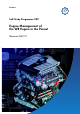
Service. Self-Study Programme 249 Engine Management of the W8 Engine in the Passat Motronic ME 7.1.
The Motronic engine management system of the W8 engine enables high power output with minimal fuel consumption through adaptation to all operating modes. The heart of the Motronic system is the electronic control unit (J220). It processes incoming signals and transmits adjustment commands for controlling the subsystems. At the same time, the control unit serves the diagnosis of subsystems and components. S249_001 For further information on the W8 engine, please refer to SSP 248 „The W Engine Concept“.
Table of Contents Introduction . . . . . . . . . . . . . . . . . . . . . . . . . . . . . . . . . . 4 System overview . . . . . . . . . . . . . . . . . . . . . . . . . . . . . 6 Subsystems . . . . . . . . . . . . . . . . . . . . . . . . . . . . . . . . . . 8 Sensors . . . . . . . . . . . . . . . . . . . . . . . . . . . . . . . . . . . . 20 Actuators . . . . . . . . . . . . . . . . . . . . . . . . . . . . . . . . . . . 28 Functional diagram . . . . . . . . . . . . . . . . . . . . . . . . . .
Introduction The Motronic ME 7.1.1 The regulation of the W8 engine is performed by the Motronic ME 7.1.1. The management system of the W8 engine is, in many respects, the same as that of the VR6-V4 engine. These are the tasks of the engine management system: - Optimisation of the fuel-air mixture for all operating modes - Reduction of fuel consumption - Regulation of combustion - Monitoring and regulation of exhaust emissions.
The engine control unit in the CAN data bus The engine control unit communicates with the control units in other vehicle systems. Data is exchanged through the CAN data bus, which joins the individual control units in a single system.
System overview Sensors G70 Air mass meter G42 Intake air temperature sender G28 Engine speed sender G62 Coolant temperature sender G83 Coolant temperature sender radiator outlet G39 Lambda probe G108 Lambda probe II Dash panel insert J285 G130 Lambda probe after catalyst G131 Lambda probe II after catalyst (control unit with display unit in dash panel insert) G40 Hall sender 1, G163 Hall sender 2 G300 Hall sender 3, G301 Hall sender 4 Radiator fan 2 G61 Knock sensor 1, G66 Knock sensor 2 G198 Knock se
Actuators J17 Fuel pump relay, G6 Fuel pump J 338 Throttle valve control part G186 Throttle valve drive N30 Injector, cylinder 1, N31 Injector, cylinder 2 N32 Injector, cylinder 3, N33 Injector, cylinder 4 N83 Injector, cylinder 5, N84 Injector, cylinder 6 N85 Injector, cylinder 7, N86 Injector, cylinder 8 N70 Ignition coil 1, N127 Ignition coil 2 N291 Ignition coil 3, N292 Ignition coil 4 N323 Ignition coil 5, N324 Ignition coil 6 N325 Ignition coil 7, N326 Ignition coil 8 N205Inlet camshaft timing a
Subsystems The fuel injection system Input signals for calculating injection periods ● ● ● ● ● ● ● ● Engine load signal from air mass meter Intake air temperature Signal from throttle valve control part Signal from engine speed sender Coolant temperature Signal from Lambda probes Signal from accelerator pedal module Signal from Hall senders 1 Fuel tank 2 Fuel pump 3 2 1 5 6 Filter 4 Fuel rail 5 Fuel pressure regulator 6 Injectors 7 Engine control unit 8 Accelerator pedal module 9 Air mass
The ignition system Input signals for calculating the ignition timing ● ● ● ● ● ● ● Signal from engine speed sender Engine load signal from air mass meter Signal from throttle valve control part Coolant temperature Signal from knock sensors Signal from Hall senders Signal from accelerator pedal module 1 Single-spark ignition coils with output stage 2 Engine control unit 3 4 5 6 7 8 3 Air mass meter 4 Engine speed sender 5 Temperature sender (G62) 9 6 Throttle valve control part 2 7 Knock sensor
Subsystems Knock control Unfavourable operating conditions can lead to self-ignition (pre-ignition knock). Consequently, the ignition timing must be adjusted. Input signals ● Signal from knock sensors ● Signal from Hall senders ● Engine temperature 1 Single-spark ignition coils with output stage 2 Engine control unit 3 Knock sensors 2 4 Hall senders 3 4 5 Spark plugs 1 5 3 4 5 1 4 3 3 S249_008 Each bank of the W8 engine is equipped with two knock sensors mounted on the crankcase.
Variable valve timing The task of variable valve timing is to set the best valve timing for the operating modes idle, maximum power and torque. Variable valve timing optimises the ratio between fresh air and exhaust gas. This is referred to as internal exhaust gas recirculation. The overlap angle, during which the inlet valve is already opening while the exhaust valve is not yet closed, determines the quantity of „recirculated“ exhaust gas.
Subsystems Stereo lambda regulation The task of the lambda regulation is to maintain a lambda value of 1 during combustion so that exhaust gases can be optimally cleaned in the catalyst.
The fuel tank ventilation system Input signals for fuel tank ventilation regulation ● ● ● ● ● Engine speed Engine load signal from air mass meter Engine speed Signal from lambda probes Signal from throttle valve control part 5 6 7 8 9 3 4 1 Fuel tank; 2 Activated charcoal filter 3 Solenoid valve for activated charcoal filter 4 Engine control unit 5 Air mass meter 6 Engine speed sender 7 Temperature sender at engine outlet 8 Lambda probes 9 Throttle valve control part 2 1 249_011
Subsystems The cruise control system (CCS) With the aid of the cruise control system, a vehicle speed above 30 km/h can be specified. This speed will then be maintained without driver intervention.
Electronic power control Input signals ● Signal from accelerator pedal module ● Additional signals 1 Throttle valve control part Additional signals 2 Engine control unit ● Cruise control system 3 Accelerator pedal module ● Air conditioning system 4 Electronic power control ● Lambda regulation (EPC) warning lamp ● Automatic gearbox 5 Ignition, ● ABS Fuel injection ● Power-assisted steering ● Alternator 3 2 1 5 4 S249_013 The driver’s input, i.e.
Subsystems The secondary air system Input signals ● ● ● ● Signal from lambda probes Coolant temperature Engine load signal from air mass meter Engine speed 7 8 11 3 2 1 6 4 1 Secondary air pump relay 2 Secondary air pump 3 Secondary air inlet valve 4 Combination valve 5 Catalyst 6 Engine control unit 7 Air mass meter 8 Temperature sender 2 at engine outlet 4 9 Pre-catalyst lambda probes 10 After-catalyst lambda probes 11 Engine speed sender 10 5 9 9 5 10 S249_014 The seco
Engine mounting regulation Input signals ● Signal from engine speed sender ● Vehicle speed 1 Electro-hydraulic engine 3 mounting solenoid valve 5 2 Engine mounting 4 3 Engine control unit 4 Engine speed sender 5 Vehicle speed To intake manifold 1 2 2 S249_015 The hydraulically damped engine mountings with electro-pneumatic actuation reduce the transmission of engine oscillation to the body over the entire engine speed range.
Subsystems Coolant temperature regulation Coolant temperature regulation enables the coolant temperature to be adapted to the current operating mode of the engine.
The regulated vacuum pump system (only for vehicles with automatic gearboxes) Input signals ● Signal from pressure sensor for brake servo 1 Relay 2 Electric vacuum pump 3 Engine control unit 4 Pressure sensor for brake servo 5 Anti-return valve 3 6 To intake valve 4 7 Brake servo 1 7 5 5 2 S249_017 6 Vehicles with an automatic gearbox are equipped with an electric vacuum pump.
Sensors Air mass meter G70 with intake air temperature sender G42 Air mass meter G70 with backflow recognition and intake air temperature sender G42 are integrated in one component which is located in the intake tract at the air filter housing. The air mass meter determines the mass of the inducted air and sender G42, the temperature.
Coolant temperature senders G62 and G83 The actual values of the coolant temperature are measured at two different points. Coolant temperature sender G62 is located on the engine block (at the coolant outlet) and coolant temperature sender G83 on the radiator outlet.
Sensors Lambda probes The broad-band lambda probes G39, G108 Broad-band lambda probe Each is located in the exhaust manifold of its specific bank upstream to the catalyst (pre-catalyst probe). With the wide-band lambda probe, the oxygen content in the exhaust gas can be determined over a wide measuring range. S249_023 The two-state lambda probes G130, G131 Each is located in the exhaust manifold of its specific bank downstream to the catalyst (after-catalyst probe).
Brake servo pressure sensor G294 (only for vehicles with automatic gearbox) The brake servo pressure sensor is located in the plenum chamber below the vacuum line to the brake servo. It transmits a voltage signal to the engine control unit. S249_027 Effects of signal failure If the signal fails, the engine control unit calculates the pressure in the brake servo on the basis of the input values for engine load, engine speed, throttle valve position and brake light switch, and actuates the vacuum pump.
Sensors Hall senders G40, G163, G300, G301 All Hall senders are located in the timing chain cover of the engine. They have the task of informing the engine control unit of the positions of the inlet and exhaust camshafts by sensing a quick-start sender wheel located on the respective camshaft.
Knock sensors G61, G66, G198, G199 The electronic regulation of ignition timing is based on cylinder-specific knock control. The W8 engine has two knock sensors on each bank, located on the crankcase. G198 G199 S249_033 S249_030 G61 G66 S249_032 S249_031 Use of signal Effects of signal failure The knock sensors indicate to the engine control unit when knocking combustion occurs. It initiates an ignition timing adjustment until the knocking ceases.
Sensors The accelerator pedal module The accelerator pedal module is located on the pedal cluster and consists of ● the accelerator pedal ● the accelerator pedal position sender G79 and ● the accelerator pedal position sender 2 G185. Both senders are sliding contact potentiometers located on a common shaft. Every change in the accelerator pedal position changes the resistance of the sliding contact potentiometers and consequently the voltage transmitted to the engine control unit.
Brake light switch F and brake pedal switch F47 The brake light switch and the brake pedal switch are located together in one component on the pedal cluster. Use of signal: S249_037 Both switches supply the engine control unit with the signal „brake operated“. This leads to the cruise control system being switched off. Clutch pedal switch F36 The clutch pedal switch is located on the pedal cluster.
Sensors / Actuators Throttle valve control part J338 The throttle valve control part is located on the intake manifold and has the task of providing the engine with the required quantity of air under all conditions. Throttle body Intake connection Throttle valve drive It differs from the control part installed in the VR6 engine in that the intake connection has a greater diameter. This is necessary because the W8 engine has a greater need for air due to its greater displacement.
Fuel pump G6 The fuel pump is installed directly in the fuel tank. With the aid of the pressure regulator, it creates a pressure of 4 bar in the fuel system. To supply the engine, fuel is delivered from the fuel pump G6 through the fuel filter to the fuel rail. G6 S249_039 S249_040 Effects of failure If the fuel pump fails, no fuel is delivered. The engine stops. In addition, fuel pump G23 is located in the additional fuel tank and a suction-jet pump in the fuel tank.
Actuators Injectors N30, N31, N32, N33, N83, N84, N85, N86 The injectors are actuated by the engine control unit according to the firing order. They are secured with retaining clips directly to a common fuel rail and inject atomised fuel immediately before the inlet valve. S249_042 Effects of failure S249_043 If individual injectors fail, fuel is not injected at that position. This means that the engine runs at reduced output. For further information, please refer to SSP 127 „VR 6 Engine“.
Inlet camshaft timing adjustment valves 1 N205 and 2 N208 and Exhaust camshaft timing adjustment valves 1 N318 and 2 N319 In the process, valves N205 and N208 are responsible for the continuous adjustment of the inlet camshafts and valves N318 and N319, for the adjustment of the exhaust camshafts. The exhaust camshaft adjusters can only be set to the end positions „advanced“ or „retarded“. The solenoid valves are integrated in the control housing of the camshaft adjuster.
Actuators Activated charcoal filter system solenoid valve 1 N80 Opening the solenoid valve empties the activated charcoal filter and directs the collected fuel vapour to combustion. Effects of signal failure If current is interrupted, the valve remains shut and tank ventilation cannot occur. S249_049 To intake manifold For further information, please refer to SSP 174 „Changes in the VR6 Engine“.
Combination valve S249_055 Vacuum from the secondary air inlet valve operates the combination valve, opening the path for air from the secondary air pump to the secondary air duct in the cylinder head. At the same time, the valve prevents hot exhaust gases from reaching the secondary air pump. S249_053 Secondary air pump V101 The secondary air pump transports fresh air for the secondary air system. S249_052 Effects of failure If the current supply is interrupted, no air is transported.
Actuators Water pump V36 The water pump V36 is located on the left side (in direction of travel) of the engine compartment on the suspension strut mounting. Depending on the coolant temperature at the radiator and engine outlets, the pump will be operated after the engine is shut off on the basis of a map. The water pump is responsible for circulating coolant so that the engine block cools uniformly.
Map-controlled engine cooling thermostat F265 S249_058 Resistance The thermostat is inserted in the upper part of the crankcase from above. The thermostat switches between the small and the large cooling circuits. The individual engine operating phases require different engine temperatures. The thermostat is actuated by the engine control unit according to the needs. A map is stored in the engine control unit to attain the desired temperature.
Actuators Function of engine mountings The engine oscillation on a bad road surface is damped by the flow of a liquid (glycol mixture) between chambers 1 and 2. The task of the damping is to reduce resonant engine oscillation due to uneven road surface. The damping is dependent on the form (length and diameter) of the spiral-shaped channel and is adapted to the particular engine in the vehicle.
Engine mounting - driving mode At a speed of about 5 km/h, the engine control unit cuts off current to the solenoid valve. The valve plate of the solenoid valve closes the connection to the intake manifold. Via the solenoid valve, atmospheric pressure reaches the positioning spring of the engine mounting. Due to the atmospheric pressure at the positioning spring, the connecting channel between chambers 1 and 2 closes.
Functional diagram Functional diagram Kl. 30 Kl.
Kl. 30 Brake lights Kl.
Functional diagram Kl. 30 Kl.
Kl. 30 Kl.
Service Self-diagnosis The engine control unit enables a broad self-diagnosis of all subsystems and electrical components. These vehicle diagnosis systems are used for communication: ● VAS 5051 ● VAS 5052 With the vehicle diagnosis, testing and information system VAS 5051, ● ● ● ● Vehicle self-diagnosis Testing Guided fault finding and Administration can be performed. VAS 5051 VAS 5052 Vehicle Diagnosis and Service Information System Version -GB- / V01.
With the vehicle diagnosis and service information system VAS 5052, ● Vehicle self-diagnosis ● Service Information System and ● Administration can be performed. VAS 5052 S249_081 The use of the vehicle diagnosis system VAS 5052 is explained in SSP 256 „VAS 5052“.
Service Read fault memory When faults occur in the system, they will be detected by self-diagnosis and stored in the fault memory. With function 02, the fault memory can be read using the vehicle diagnosis systems. The following components are monitored by self-diagnosis.
Erase fault memory This function erases the contents of the fault memory following „Read fault memory“. However, the readiness code and various adaptation values such as the camshaft and lambda adaptation values will also be erased. To ensure that the fault memory is properly erased, the ignition must be switched off once. Following „Erase fault memory“, one must check whether the camshafts have readapted themselves.
Test Your Knowledge 1. The engine control unit receives the signal for engine load from a. the lambda probes. b. the air mass meter. c. the accelerator pedal module. 2. Which tasks does the secondary air system perform? a. It elevates exhaust emissions during the cold start phase. b. It ensures that the engine operates with excess air. c. The secondary air system increases performance in the partial-load range. d. Secondary air injection brings the catalyst up to operating temperature more quickly. 3.
5. If a temperature sender fails a. the radiator fans go to emergency running mode. b. the engine stops. c. the control unit uses a substitute temperature stored in the engine control unit. 6. The electro-hydraulic engine mountings can change in their mounting characteristic. A pneumatic 3/2-way solenoid valve is actuated by the engine control unit. Which statements are true? a. Current is supplied to the solenoid valve at 5 km/h. b. Current is cut off to the solenoid valve at 5 km/h. c.
Notes 48
Notes 50
Answers 1.) b 2.) d 3.) c 4.) b 5.) a, c 6.) b, c 7.
249 For internal use only © VOLKSWAGEN AG, Wolfsburg All rights reserved. Technical specifications subject to change without notice 140.2810.68.20 Technical status 11/01 ❀ This paper was produced from non-chlorine-bleached pulp.