Battery Charging Centre ALC 8500-2 Expert Operating Instructions
GB Contents: 1 Introduction .................................................................................................................... 1.1 The essential performance features of the ALC 8500-2 Expert . ................................... 1.2 Proper use . .................................................................................................................... 2 Safety Notes ..................................................................................................................
1 Introduction Rechargeable cells, and rechargeable battery packs in particular, are a basic requirement for mobile equipment, and nowadays they have found their way into virtually all areas of daily life. Today’s consumers expect mobility, especially in the world of communication, and without suitable rechargeable energy storage devices this would all be unthinkable, as primary cells (dry cells) are too expensive to be a viable alternative for many applications.
Table 1: performance data of the ALC 8500-2 Expert Nominal battery capacity, channels 1 and 2.................................................. 200 mAh to 200 Ah Nominal battery capacity, channels 3 and 4.................................................... 40 mAh to 200 Ah Charge power, channels 1 and 2.........................................................................max. 40 VA total Discharge power, channels 1 and 2........................................................max.
1.2 Proper use The charger is designed for charging (fast and normal), discharging and trickle-charging batteries based on the following technologies: NiCd, NiMH, Lead-Acid, Lead-Gel, Li-Ion and Li-Po. The maximum charge current is 5 A, and the unit can charge batteries with a nominal voltage in the range 1.2 V to 24 V (NC, NiMH). No other type of use is permissible; any other usage invalidates the guarantee and negates our liability.
– If you are not sure about any aspect of the machine, do not use it. Consult our Service Department for advice. Caution! Before connecting any battery to the charger please check the pack for damage and signs of oxidation, damaged seals and leakage. Don’t attempt to recharge any battery in this condition; it is best simply to dispose of it in the appropriate manner, as printed in the disposal label on the pack.
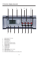
3 Controls, display elements 14 2 1. 2. 3. 4. 5. 6. 7. 8. 9. 10. 11. 12. 13. 14. 15. 16.
4 Charge processes, charge outputs During the charge process the micro-controller constantly monitors the course of the voltage at each charge output individually. A series of successive measured values is used to assess the charge curve. For best possible results from the charge process the ALC 8500-2 Expert constantly monitors the charge curve for the appropriate battery type with 14-bit accuracy. Reliable detection of the optimum charge cut-off point is particularly important.
The main display window always shows whether a particular channel is actively working, and which process is being carried out. A channel LED is also located above each pair of output sockets; the LED glows constantly when its associated channel is working actively. When the process is concluded, the LED lights up briefly every 1.5 seconds. If the process is terminated in an emergency situation, the LED flashes at a high rate.
However, these transfer resistances generally remain unchanged relative to each other. For this reason it is always worthwhile carrying out an optimisation process in any high-current application. This involves eliminating unnecessary connectors, and using short cables of generous cross-section wherever possible. All connectors should exhibit a large contact area and be a firm, secure fit.
7 Lead-acid activator (reviver) function The ALC 8500-2 Expert features a lead-acid activator function which can be selected when charging a lead-acid battery at channel 2. This function eliminates the problem of crystalline sulphate deposits on the plates of lead-acid batteries which have not been used for a long time, or are only ever discharged at low currents when in use. Lead-acid batteries are designed to provide a useful life of eight to ten years or more, provided that they are maintained properly.
8 Data logger The purpose of the data logger is to record complete charge / discharge processes, independently of a PC. The data logger is capable of simultaneously recording the charge / discharge process curves for all four channels, and the recorded data is retained in the charger’s flash memory even when the operating voltage is switched off.
The detailed information displayed is as follows: the battery technology (type) selected for the function currently running, the battery voltage, the charge current and the capacity of the selected channel. The bottom half of the screen continues to display the overall summary of all four channels. Channel not used Charge Charged (full) Discharge Discharged (empty) Waiting Pause Puls-Charge Error Fig.
10.3 Channel windows In addition to the main window, four channel windows are available which can be called up using the arrow buttons under the screen. When a channel window is called up, the whole screen is available for that channel. Fig. 4 shows the functions now available using the arrow buttons.
11 Main Menu Starting from the main window, a brief press of the “OK / Menu” button calls up the main menu (ALC 8500-2 Expert Main Menu). The lower part of the screen displays the message: “Main-Menu, ChanMenu?” (Fig. 7). If you wish, you can now use the arrow buttons or the jog dial to select further menus in the main menu, or press the “OK / Menu” button to move to the Channel menu where you can select the desired settings Fig. 7: The main menu and enter battery data for the individual charge channels.
12.3 Conf. Bat. (configuring batteries) If you select “No Name” at the “Battery” stage, you now have to configure the battery to be charged. When you call up the menu, the window shown in Fig. 11 appears. First you must confirm your selection with the “OK / Menu” button, then select the battery technology (type). Confirm your choice again, then enter the nominal capacity of the pack using the jog dial. To speed up data input you can edit the point to be changed (flashing) using Fig.
Fig. 17: Entering the charge / discharge interval Fig. 18: Function select menu 12.3.1 Charge rates C/20: the battery is charged (or discharged) at a very low current corresponding to one twentieth of its nominal capacity. C/10: at this setting the battery is charged (or discharged) at a current corresponding to one tenth of its nominal capacity. A charge factor of 1.4 is used, which means that a fully discharged NC or NiMH battery is charged for fourteen hours at this current.
12.4 Function When you call up the “Function” menu you see the display window shown in Fig. 19, with “Select Function” in the bottom half. Once again, you can use the jog dial or the arrow buttons to select the desired processing function; all the functions described in detail under 12.4.1 to 12.4.8 are available. The selected function is shown in the central area of the top half of the screen. Fig. 19: Selecting the desired function 12.4.
12.4.5 Refresh The Refresh function of the ALC 8500-2 Expert is primarily intended for use with defective or damaged batteries, most of which can be re-used after subjecting them to this program. This applies in particular to deep-discharged batteries, and packs stored for a long time, but also to batteries which exhibit a cell short, all of which are often usable again after this process has been completed.
After you have selected the processing function you wish to use, all the essential parameters for processing the battery pack are concluded, and are displayed on the screen when you confirm your selection by pressing the “OK / Menu” button briefly. Now press the “OK / Menu” button again to initiate the process. The program returns to the main menu; confirm once more with “Return”, and the screen displays the main window again.
The higher the internal resistance of the battery, the worse the voltage curve under load conditions, and the more dissipated power is converted into heat within the cell and at the parasitic transfer resistance points. At high currents parasitic resistances in the mOhm range can certainly cause considerable voltage losses at the motor or other consumer. The Ri function can also be used as a straightforward means of measuring internal resistance in the system as a whole. First set the Fig.
14. Conf. menu The configuration menu is a further sub-menu (Fig. 24) available from the Main Menu. This is where you access the menus for configuring the ALC 8500-2 Expert and the batteries stored in its internal database, as described in the next section. To reach the configuration menu select the “Conf.-Menu” sub-menu from the “Main Menu”, and confirm by pressing “OK / Menu”. The Conf.-Menu now offers the menu points listed in Fig. 25: Return? Database? C/D-Para? Fig.
14.1.3 Del. Bat. This function is used to erase batteries which are stored in the database but no longer required. Call up the database, select the battery to be erased using the jog dial or the arrow buttons, then confirm your selection (“OK / Menu” button) to erase the battery from the database. 14.1.4 Return To return to the Conf. Menu, press “Return”, then confirm by pressing the “OK / Menu” button. 14.2 C/D-Para The charge / discharge parameters are configured in the “C/D-Para” menu (Fig. 28).
CyCy NiMH Maximum cycle count for NiMH batteries in the “Cycle” function; variable in the range 2 to 20 cycles CyFo NC Maximum cycle count for NC batteries in the “Form” function; variable in the range 2 to 20 cycles CyFo NiMH Maximum cycle count for NiMH batteries in the “Form” function; variable in the range 2 to 20 cycles Restore If you select “Restore” and confirm it by pressing the “OK / Menu” button, all charge / discharge parameters are returned to the standard default values.
15 Display of charged-in / discharged capacity During the charge process the charged-in capacity is continuously updated and displayed directly on the screen. During the discharge process the same applies to the capacity discharged from the battery. After the conclusion of the process the capacity of the last completed action can be read off on the screen; with the exception of the Discharge process this will always be the charged-in capacity.
When a process is concluded and the function stopped, the data in the flash memory is retained indefinitely even when the device is switched off, but only until such time as you make changes to the corresponding charge channel. However, for data retention it is essential that the function be stopped before you switch the charger off, unless the process has already reached the “trickle charge” state.
18.7 Error messages The ALC 8500-2 Expert incorporates a comprehensive set of safety functions, and automatically halts the current process if any important parameter strays outside the permissible range. After an automatic forced shut-down the screen displays an exclamation mark (“!”) in the overall view (main window). If this happens, use the arrow buttons to switch to the appropriate charge channel, and you will see an indication of the reason for the enforced shut-down in the bottom half of the screen.
19 Maintenance, care Always disconnect the machine from the mains supply before cleaning it, using only a soft dry cloth. If the case gets very dirty the cloth can be slightly moistened. Remove all traces of moisture with a dry cloth before re-using the charger. Do not immerse the ALC 8500-2 Expert in water! Do not use solvent-based cleaning agents to clean the charger. If a fault occurs with the charger, do not open the case, as it contains no parts which you can repair or replace yourself.
20 Specification No. of charge channels:.......................................................................................................................... 4 Nominal battery voltage:...................................... Channels 1 + 2 max. 24 V, channels 3 + 4 max. 12 V Charge current:............................................ Channels 1 + 2 max. 5 A (charge power max. 40 VA total) Channels 3 + 4 max. 1 A total Discharge current:....................................................