
Instructions


Digital Storage Oscilloscope 7
miscompensated probes may lead to errors or faults in measurement. To adjust the
probe compensation, follow the steps below.
1. Set the Probe option attenuation in the channel menu to 10X. Set the switch on the
probe to 10X and connect the probe to Channel 1 on the oscilloscope. If you use the
probe hook-tip, ensure it is firmly inserted onto the probe. Attach the probe tip to the
PROBE COMP ~2V@1KHz connector and the reference lead to the PROBE COMP
Ground connector. Display the channel and then press the Auto Scale button.
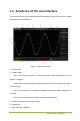
2. Check the shape of the displayed waveform.
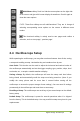
3. If necessary, use a nonmetallic screwdriver to adjust the variable capacity of your
probe until the shape of the waveform turns to be the same as the above figure.
Repeat this step as necessary. See the figure below for the way of adjustment.
1.5.4 Probe Attenuation Setting
Probes are of various attenuation factors which affect the vertical scale of the signal.
The Probe Check function is used to verify if the Probe attenuation option matches the
attenuation of the probe.
You can push a vertical menu button (such as the CH1 MENU button) and select the
Probe option that matches the attenuation factor of your probe.
Make sure that the Attenuation switch on the probe matches the Probe option in the
oscilloscope. Switch settings are 1X and 10X.
When the Attenuation switch is set to 1X, the probe limits the bandwidth of the
oscilloscope to 6MHz. To use the full bandwidth of the oscilloscope, be sure to set the
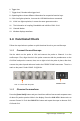
Compensated correctly
Overcompensated
Undercompensated