
User manual

Digital Storage Oscilloscope 37
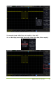
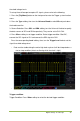
sources and SDA data sources. Below is the sequential chart of SPI bus.
1. Press the [Trig Menu] button on the front panel to enter the Trigger system function
menu.
2. Press the Type softkey, then turn the Universal Knob to select SPI and push down
the knob to confirm.
3. Source Selection: Press SCL and SDA softkey to specify the data sources of SCL
and SDA respectively. They can be set to CH1-CH4.
Note: Select channel with signal input as trigger source to obtain stable trigger.
4. Data Line Setting:
Press Data Width to set the number of bits of the serial data character string. The
serial data string can be specified to be from 4, 8, 16, 24, 32 bits long.
Press Data to set the value of the current bit from 0 to f.
Data Mask: 0-Mask, f-No Mask, 1~e mask some data.
5. Trigger Condition: Press Overtime softkey to set the timeout, the range is from 8 ns
to 10 s.
Timeout: the clock (SCL) signal need to maintain a certain idle time before the
oscilloscope searches for a trigger. The oscilloscope will trigger on when the data (SDA)
satisfying the trigger conditions is found.
6. Slope: Clock Edge: Press Slope softkey to select the desired clock edge.
Rising: sample the SDA data on the rising edge of the clock.
Falling: sample the SDA data on the falling edge of the clock.
7. When select SCL channel, press SCL and use Trigger Level knob to modify the
trigger level of the SCL channel. When select SDA channel, use Trigger Level knob to
modify the trigger level of the SDA channel.
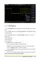
2.7.14 IIC Trigger
IIC (Inter-IC bus) signals setup consists of connecting the oscilloscope to the serial
data (SDA) line and the serial clock (SCL) line and then specifying the input signal