Dual-Channel Arbitrary Waveform Generator User Manual FG-30802T FG-31602T FG-32502T
Table of Contents 1. General Safety Requirement................................................................... 1 2. Safety Terms and Symbols....................................................................... 2 3. Quick start................................................................................................3 Front panel.................................................................................................................................. 3 Rear Panel............................
Frequency Modulation (FM)............................................................................................. 29 Phase Modulation (PM).................................................................................................... 31 Pulse Width Modulation (PWM)...................................................................................... 32 Amplitude shift keying (ASK).............................................................................................
Connect Directly................................................................................................................62 Connect through a Router................................................................................................ 63 6. Troubleshooting.....................................................................................65 7. Specification...........................................................................................66 8. Appendix.............................
1.General Safety Requirement 1. General Safety Requirement Before use, please read the following safety precautions to avoid any possible bodily injury and to prevent this product or any other connected products from damage. In order to avoid any contingent danger, ensure this product is only used within the range specified. Only the qualified technicians can implement the maintenance. To avoid Fire or Personal Injury: Use Proper Power Cord.
2.Safety Terms and Symbols 2. Safety Terms and Symbols Safety Terms Terms in this manual. The following terms may appear in this manual: Warning: Warning indicates the conditions or practices that could result in injury or loss of life. Caution : Caution indicates the conditions or practices that could result in damage to this product or other property. Terms on the product. The following terms may appear on this product: Danger: It indicates an injury or hazard may immediately happen.
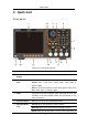
3.Quick start 3. Quick start Front panel Figure 3- 1 Front Panel overview 1 Display Area Display user interface (8-inch capacitive touch screen) 2 Menu Selection Button Includes 6 buttons to select the corresponding menu softkey 3 Mode Button Area Modulation (Mod): Output modulation waveform Sweep: Scan a sine wave, square wave, ramp wave or arbitrary wave Burst: A burst that produces a sine wave, square wave, ramp wave, pulse wave, or arbitrary wave.
3.Quick start power-on parameters; save or read the settings file. Utility: Set the auxiliary system function Store: Save/recall arbitrary waveform data Help: To get context help for any front panel button or menu softkey, press the button and then press the button for which you need help. 7 Numerical Keypad Input the parameter 8 CH2 Button Area CH2 key: Enter the waveform interface and select the CH2 channel (the backlight of the button lights up).
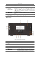
3.Quick start lights up. 15 Waveform Selection Area Including: sine , square , ramp , pulse , noise , arbitrary wave , harmonic waves . When one waveform is selected, the corresponding backlight will be lit. 16 USB Interface Connect to an external USB Host device, such as a USB flash drive. 17 Power Button Turn on/off the waveform generator Rear Panel Figure 3- 2 Rear Panel Overview 1 Retractable Handle 2 Vents 3 Power Input Socket AC power input interface.
3.Quick start 7 USB Device Interface Used to connect a USB type B controller. The PC can be connected to communicate with the signal generator through the host computer software. 8 Keyhole A safety lock (please buy it yourself) can be used to lock the instrument in a fixed position to secure the instrument. 9 10MHz In/Out/Counter(Reference clock input / output / frequency meter input) connector The default is to receive the frequency meter input signal.
3.Quick start User Interface Figure 3- 3 User Interface 1 Display channel name and channel status 2 Current waveform or current mode 3 Trigger source. Internal: internal modulation or internal trigger source External: external modulation or external trigger source Manual: manual trigger source 4 Load, High Z indicates high resistance 5 This icon is lit when the network is connected through the LAN interface. This icon is lit when connected to the USB Host via the USB DEVICE 6 interface.
3.Quick start 15 Frequency/cycle, depending on the right highlighted menu item Use Build-in Help (1) To get help on any front panel button or menu softkey, press the front panel Help function button first, then press the button you need help. (2) Press the Help function key again to exit the help interface.
4.Panel Operation 4. Panel Operation Channel Setting Select the channel for configuration Before configuring waveform parameters, you must select the channel you want to configure. Press CH1 or CH2 to select the corresponding channel, and the corresponding channel area in the user interface will light up Turn On/Off Channel Output Press the front panel CH1 On/Off or CH2 On/Off button to turn the output of the corresponding channel on/off.
4.Panel Operation Output Sine Wave Press , the screen displays the user interface of the sine wave. By operating the sine wave menu on the right side of the screen, you can set the output waveform parameters of the sine wave. The sine wave menu includes: frequency/period, amplitude/high level, offset/low level, and start phase. The menu can be operated by the menu selection button on the right.
4.Panel Operation select the unit of the parameter. Press the Cancel softkey to cancel the current input parameter value. Figure 4- 2: Use the numeric keypad to set the frequency Set the amplitude Press the Amplitude/High Level softkey to confirm whether the Amplitude menu item is highlighted; if not, press the Ampl/High button to switch to Amplitude. In parameter 2 of Figure 5-1, the parameter value of the amplitude appears as a blinking cursor. Use the knob or numeric keypad to set the desired value.
4.Panel Operation parameter 3 of Figure 5-1, a low-level parameter value appears as a blinking cursor. Use the knob or numeric keypad to set the desired value. Set the start phase Press the Start Phase softkey to confirm whether the Start Phase menu item is highlighted; if not, press the Start Phase key. In parameter 4 of Figure 5-1, the parameter value of the starting phase appears as a blinking cursor.
4.Panel Operation Output Ramp Wave Press , the screen displays the user interface of the ramp wave. By operating the ramp menu on the right side of the screen, you can set the output waveform parameters of the ramp wave. The ramp menu includes: frequency/period, amplitude/high level, offset/low level, symmetry. For the setting frequency/period, amplitude/high level, offset/low level, and starting phase, please refer to Output Sine Wave on page 10.
4.Panel Operation display the symmetrical value of the input, press the X soft key to delete the last digit, press the ← soft key to cancel the input, and press the Enter softkey to indicate the default input. Figure 4- 5: Set the symmetry of ramp wave Output Pulse Wave Press , the screen displays the user interface of the pulse wave. By operating the pulse wave menu on the right side of the screen, the output waveform parameters of the pulse wave can be set.
4.
4.Panel Operation Glossary Pulse Width PW is an abbreviation for pulse width and is divided into positive pulse width and negative pulse width. The positive pulse width is the time interval from 50% of the rising edge to 50% of the adjacent falling edge. The negative pulse width is the time interval from 50% of the falling edge to 50% of the adjacent rising edge. The pulse width is determined by the period and duty cycle of the signal. The calculation formula is pulse width = period * duty cycle.
4.Panel Operation Set the pulse width/duty cycle Press the Pulse Width/Duty Cycle softkey to select the Pulse Width menu item. As shown in Figure 5-7, parameter 1 displays the current value of the pulse width. Press the Pulse Width/Duty Cycle button to display the duty cycle.
4.Panel Operation Set the rising/falling time Press the rise time / fall time soft key to select the "rise time / fall time" menu item, as shown in Figure 5-6, parameter 6 shows the current value of the rise/fall time; press the rise time / fall time key to switch between the current display. Parameter value.
4.Panel Operation Figure 4- 8: noise wave user interface Output Arbitrary Wave Press , the screen displays the user interface of the arbitrary wave. By operating the arbitrary wave menu on the right side of the screen, the output waveform parameters of the arbitrary wave can be set. Arbitrary wave menus include: frequency/period, amplitude/high level, offset/low level, start phase, built-in waveform.
4.Panel Operation Figure 4- 9: Arbitrary wave user interface Choose build-in waves There are 152 types of waveforms built into the system, the number of waveform points is 8192 points, and the highest upper limit frequency is 15MHz.
4.Panel Operation (3) Turn the knob to select the desired waveform, for example, select Airy. Press the OK soft key to enter the Airy function.
4.
4.
4.
4.Panel Operation TV signal TV Voice signal Voice Segement Modulation AM Sinusoidal segmented AM wave FM Sinusoidal segmented FM wave PM Sinusoidal segmented PM wave PWM Pulse width segmented PWM wave Output Harmonic Wave Press to display the harmonic user interface. You can set the harmonic output waveform parameters by operating the harmonic menu on the right side of the screen.
4.Panel Operation Press the Harmonic Type softkey menu and the instrument outputs the fundamental and even harmonics. Odd harmonic Press the Harmonic Type softkey menu and the instrument outputs the fundamental and odd harmonics. Order harmonic Press the Harmonic Type softkey menu and the instrument outputs the fundamental and harmonics in sequence. customize Press the Harmonic Type softkey to customize the number of times the harmonics are output. The maximum number of times is 16.
4.Panel Operation Figure 4- 10 harmonic wave user interface Output the modulated waves After pressing the Mod function key, press the F1 key to select the modulation type to output the modulated waveform.
4.Panel Operation Figure 4- 11: Amplitude modulation user interface How to set the parameters of amplitude modulation (1) After pressing the Mod function key, press the Modulation type soft key, use the knob to select, the modulation type is AM, press the OK soft key. (2) Press to display the waveform and parameters of the current carrier. You can change the parameters of the carrier. For details, please refer to Output Sine Wave on page 10. Press or Mod to return to the modulation mode interface.
4.Panel Operation Glossary AM frequency: the frequency of the modulation waveform. Modulation Depth:The range of amplitude variations of the output modulation waveform. At 0% modulation, the output amplitude is half of the set amplitude. At 100% modulation, the output amplitude is equal to the specified value. For external sources, the AM depth is controlled by the signal level on the Ext Mod In connector. +1 V corresponds to the currently selected depth of 100%.
4.Panel Operation can change the parameters of the carrier. For details, please refer to Output Sine Wave on page 10. Press or Mod to return to the modulation mode interface. (3) Press Source to select the source. If External is selected, connect the external signal source to the Ext Mod In interface on the rear panel and skip to step (5). If you select Internal, continue with the following steps. (4) Press Modulation Waveform to select the modulation waveform type.
4.Panel Operation Phase Modulation (PM) The output modulation waveform consists of a carrier wave and a modulated wave. The carrier wave can be a sine wave, a square wave, a ramp wave, or an arbitrary wave. In phase modulation, the phase of the carrier varies with the instantaneous voltage of the modulation waveform.
4.Panel Operation (5) Press the Phase Modulation Frequency softkey to set the phase modulation frequency. The range is from 2 mHz to 100 kHz (for internal sources only). (6) Press Phase Deviation to set the phase deviation, which is the offset of the phase, ranging from 0° to 180°. Pulse Width Modulation (PWM) The output modulation waveform consists of a carrier wave and a modulated wave.
4.Panel Operation (4) Press Source to select the source. If External is selected, connect the external signal source to the Ext Mod In interface on the rear panel and skip to step (6). If you select Internal, continue with the following steps. (5) Press Modulation Waveform to select the modulation waveform. You can select Sine, Square, Ramp, Noise, or Arb. (6) Press the PWM Rate softkey to set the PWM rate, which can be set from 2 mHz to 100 kHz (for internal sources only).
4.Panel Operation (1) After pressing the Mod function key, press the Modulation type soft key, use the knob to select, the modulation type is ASK, press the Enter soft key. (2) Press to display the waveform and parameters of the current carrier. You can change the parameters of the carrier. For details, please refer to Output Sine Wave on page 10. Press or Mod to return to the modulation mode interface. (3) Press Source to select the source.
4.Panel Operation Phase Shift Keying (PSK) The output modulation waveform consists of a carrier wave and a modulated wave. The carrier wave can be a sine wave, a square wave, a ramp wave, or an arbitrary wave. In phase modulation, the phase of the carrier varies with the instantaneous voltage of the modulation waveform.
4.Panel Operation when input logic high level. When the slope is "negative", the opposite is true. (4) Press the PSK softkey to set the PSK rate, which can be set from 2 mHz to 1 MHz (for internal sources only). (5) Press Phase Deviation to set the phase deviation. The range is from 0° to 360°. The default is 0°.
4.Panel Operation Frequency Shift Keying (FSK) Using frequency shift keying modulation, the output frequency is shifted between two preset frequency values (carrier frequency and hopping frequency). The frequency at which the output moves between the two frequencies is determined by the internal frequency generator (internal source) or the signal level (external source) on the rear panel Ext Trig/Burst/Fsk In interface. The carrier wave can be a sine wave, a square wave, a ramp wave, or an arbitrary wave.
4.Panel Operation output the carrier frequency when input logic low level, and output the frequency hopping frequency when input logic high level. When the slope is "negative", the opposite is true. (4) Press the FSK Rate softkey to set the FSK rate, which can be set from 2 mHz to 1 MHz (for internal sources only). (5) Press the Frequency Hopping softkey to set the frequency hopping, which is the alternating frequency.
4.Panel Operation (2) Press to display the waveform and parameters of the current carrier. You can change the parameters of the carrier. For details, please refer to Output Sine Wave on page 10. Press or Mod to return to the modulation mode interface. (3) Press the FSK Rate softkey to set the 3FSK rate, which can be set from 2 mHz to 1 MHz. (4) Press the Frequency Hopping 1 Frequency Hopping 2 softkey to select the setting frequency hopping, which is the alternating frequency.
4.Panel Operation (1) After pressing the Mod function key, press the modulation type soft key, use the knob to select, the modulation type is 4FSK, press the enter key. The carrier waveform can be selected as needed. The following is a sine wave. (2) Press to display the waveform and parameters of the current carrier. You can change the parameters of the carrier. For details, please refer to Output Sine Wave on page 10. Press or Mod to return to the modulation mode interface.
4.Panel Operation Steps to set frequency shift keying modulation (1) After pressing the Mod function key, press the modulation type soft key, use the knob to select the modulation type as BPSK, and press the ENTER key. The carrier waveform can be selected as needed. The following is a sine wave. (2) Press to display the waveform and parameters of the current carrier. You can change the parameters of the carrier. For details, please refer to Output Sine Wave on page 10.
4.Panel Operation Steps to set frequency shift keying modulation (1) After pressing the Mod function key, press the Modulation type soft key, use the knob to select the modulation type as OSK, and press the enter key. The carrier waveform can be selected as needed. The following is a sine wave. (2) Press to display the waveform and parameters of the current carrier. You can change the parameters of the carrier. For details, please refer to Output Sine Wave on page 10.
4.Panel Operation Output the sweep frequency (Sweep) In the sweep mode, the frequency is output from the start frequency to the end frequency according to the sweep type change frequency within the specified sweep time. Sweeping can only be performed using sine, square, ramp or arbitrary waves. Figure 4- 22: Sweep mode user interface Steps to set the scan mode (1) In the sine wave, square wave, ramp wave or arbitrary wave interface, press the Sweep function key to enter the scan mode.
4.Panel Operation (5) Press the Start Frequency / Center Frequency softkey to select the start frequency or center frequency and set the corresponding value, as shown in Figure 1. (6) Press the End Frequency/Frequency Range softkey to select the end frequency or frequency range and set the corresponding value. See Figure 1 for details.
4.Panel Operation Set N cycle burst Figure 4- 23: N cycle burst user interface (1) In the sine wave, rectangular wave, ramp wave, pulse wave or arbitrary waveform interface, press the Burst function key to burst. (2) Press , , , or to select the waveform function. For example, when selecting a sine wave, press to display the waveform and parameters, and change the parameters. For details, please refer to Output Sine Wave on page 10, and then press to return to the burst mode interface.
4.Panel Operation waveform is output until a trigger event is received. Note: In Burst mode, the upper limit of the carrier frequency is half of the maximum frequency of the original carrier. Taking a sine wave as an example, the maximum carrier frequency is 200MHz. Press to set the carrier to 200MHz. Then press the Burst softkey menu, then press or Burst to display the original carrier frequency to 100MHz.
4.Panel Operation Figure 4- 24: gated burst user interface (1) In the sine wave, square wave, ramp wave, pulse wave or arbitrary waveform interface, press the Burst function key. (2) Press 、 、 、 or to select the waveform function. For example, when selecting a sine wave, press to display the waveform and parameters, and change the parameters. For details, please refer to Output Sine Wave on page 10.
4.Panel Operation For low frequency large signals or signals with slow rising edges, low sensitivity is selected and the measurement results are more accurate. Press the HF Suppression softkey to toggle ON or OFF high frequency rejection. High-frequency rejection can be used to filter high-frequency components when measuring low-frequency signals, improving measurement accuracy.
4.Panel Operation Screen Saver If there is no operation during the set screen saver time, the screen enters the protection mode (the screen display is turned off, that is, the black screen). Press any key to redisplay the operation interface. (1) Press the Utility softkey, select Display Settings, and press the Screen Saver softkey to select the On/Off screen saver. (2) When the screen saver is turned on, the screen saver time can be set.
4.Panel Operation two channels. This signal is output from the front panel [Sync] connector. (1) Sync Switch Enable or disable the sync signal on the [Sync] connector. Press Utility to set CH1 sync/CH2 sync and select “On” or “Off” sync signal output. The default is "on", which sends the sync signal to the [Sync] connector. The output level on the [Sync] connector is a logic low when the sync signal is turned off.
4.Panel Operation level of the part under test. The load impedance settings provided are only for the convenience of the user to match the display voltage to the desired load. The step to set the CH1 or CH2 load value is as follows: (1) Press the Utility function button to select the CH1/2 setting. Press CH1 Load to select CH1 load, or press CH2 Load to select CH2 load; press again to switch to high impedance or *ohm ("*" represents a value).
4.Panel Operation other three nnn ranges from 0 to 255. It is recommended to ask your network administrator for an available IP address. Press Gateway and select Gateway. Use the numeric keypad and knob keys to enter the desired gateway address. The default gateway format is nnn.nnn.nnn.nnn. The first nnn ranges from 1 to 223 (except 127), and the other three nnn ranges from 0 to 255. It is recommended to consult your network administrator for an available IP address.
4.Panel Operation clock source, and then press the soft key to switch. Internal/External Warning: The clock source defaults to the internal clock source. When an external clock source is required, this function is switched to the outside. At this time, the clock source forcibly outputs the output. When the clock source output selection is turned on, the clock source must be switched to internal, and the frequency meter function stops after the clock output is turned on.
4.Panel Operation menu is “Factory Settings” to press the “Reset” soft key for factory setting. ). The factory default parameter values are as follows Output Configuration CH1 signal output switch Factory Setting OFF CH2 signal output switch OFF Function Sine Frequency 1 kHz Amplitude/offset 1 Vpp / 0 Vdc Waveform Configuration Frequency Factory Setting 1.000kHz Period 1.000ms Amplitude 1.000Vpp Offset 0.
4.Panel Operation Modulation depth 100% Source Internal Frequency modulation 100.000Hz frequency Frequency offset 100.000Hz Phase modulation frequency 100.000Hz Phase deviation 0deg PWM rate 100.000Hz Duty cycle deviation 0.0% ASK rate 100.000Hz ASK amplitude 1.000Vpp PSK rate 100.000Hz PSK phase deviation 0deg FSK rate 100.000Hz Frequency hopping 100.000Hz Frequency hopping 1 100.000Hz Frequency hopping 2 100.000Hz Frequency hopping 3 100.000Hz Code rate 100.
4.Panel Operation Trigger interval 1.000s Burst mode N cycle Number of cycles 1 Trigger source Internal Slope Positive Polarity Positive Counter Coupling Factory Setting Sensitivity Low High frequency suppression ON Trigger level 0.
4.Panel Operation Accessibility Factory Setting Backlight 100% Screen saver turn on Screen saver time 30Minute Separator Space CH1 synchronization shut down CH2 synchronization shut down CH1 load 50ohm CH2 load 50ohm USB device USBTMC IP address 192.168.1.99 Gateway 192.168.1.1 Subnet mask 255.255.255.
4.Panel Operation similar to the step. (3) Select a template: Press the Template softkey to select blank, sine, square, ramp, and noise. (4) Edit Waveform Point: Press to edit the waveform point to enter the Edit Waveform Point menu. Select the number of points and enter the number of the point you want to set. Select the voltage and enter the voltage value to be set at this point. Repeat this step to set all the points you want to set. Press Store to enter the file system interface.
4.Panel Operation Save Current Arbitrary Wave (1) Press the button to enter the Arbitrary Wave menu and configure the waveform parameters. (2) Press the front panel Store function key to enter the file system. If you want to save the current arbitrary waveform to the built-in memory, select INTER and press to enter the soft key. Turn the knob to select one of the USER files (EditMemory cannot be selected) and press the Save softkey. (The file size is displayed on the right side of the USER file.
4.Panel Operation To call up the waveform file in the internal memory, select INTER under the memory selection interface and press to enter the soft key. Turn the knob to select a file and press to call up the softkey. If the reading is successful, the screen will prompt “File Read Successful”. Note: The file size is displayed on the right side of the file. If 0B is displayed, the file is empty.
4.Panel Operation USB storage device. Up to 16 instrument settings can be saved in the instrument's internal memory. To save more settings, use a USB storage device. The settings file saved to the USB storage device uses the extension CFG. The saved settings can be restored from files in the internal memory or USB storage device. Operation Steps: Press the front panel Preset function key to enter the preset menu, and press the Save/Read Settings soft key to enter the memory selection interface.
5.Communicate with PC 5. Communicate with PC Supports communication with a computer via a USB port or a LAN port. Using the Waveform Editor software installed on the computer, the signal generator can be operated on the computer to control the output of the signal generator. Here's how to connect to a computer. First, install the Waveform Editor software on the CD-ROM on your computer. Then, there are several connection options to choose from.
5.Communicate with PC any value from 0 to 4000. However, since ports below 2000 are often occupied, it is recommended to set it to 2000 or higher. Here, it is set to "3000". Figure 5- 1 Setting the network parameters of the host computer (4) Set the network parameters of the signal generator. In the signal generator, press Utility → I/O Setup → Network setting to enter the submenu. Set the IP address and port to the IP and port in the PC software port settings in step (3).
5.Communicate with PC (4) Set the network parameters of the signal generator. In the signal generator, press Utility → I/O Setup → Network setting to enter the submenu. Set the IP address and port to the IP and port in the PC software port settings in step (3). The gateway settings need to be the same as the gateway settings of the router. After the shutdown and restart, if the data can be obtained normally in the PC software, the connection is successful.
6.Troubleshooting 6. Troubleshooting 1. If the instrument is still black and there is no display when you press the power switch, please follow the steps below: Check if the power connector is connected. Check that the voltage selector is in the correct gear position. Check that the fuse at the power connector meets the specified type and rating and is blown (can be opened with a flat-blade screwdriver). After completing the above checks, restart the instrument.
7.Specification 7. Specification All specifications apply to this product unless otherwise stated. The signal generator must be operated continuously for more than 30 minutes at the specified operating temperature to meet these specifications. In addition to the specifications marked with the word "Typical", the specifications used are guaranteed.
7.Specification Amplitude accuracy Amplitude resolution DC offset range (High resistance,open circuit) DC offset range DC offset accuracy Offset resolution Output Impedance 1mVpp to 10Vpp (≤ 40MHz) 1mVpp to 5Vpp (≤80MHz) 50 Ω 1mVpp to 2.5Vpp (≤120MHz) 1mVpp to 1Vpp (≤250MHz) ±(1% of setting + 1 mVpp) (Typical value 1kHz sine, 0V offset) 1 mVpp or 4 digits ±(10 Vpk – Amplitude Vpp/2) ±(5 Vpk – Amplitude Vpp/2) ±(1 % of |setting| + 1 mV + amplitude Vpp * 0.
7.Specification Duty cycle Rise and fall time Overshoot Jitter Noise Types Bandwidth (-3dB) Arbiratry wave Bandwidth 0.3% to 99.7% ≥7ns < 3% 300ps + 100ppm Waveform length 2 to 1M points Sampling rate < = 312M (at frequency <25kHz) 1.
7.
7.
7.
7.Specification Input level range Lock time Lock range External clock output Frequency Impedance Amplitude Sync Output Level Maximum frequency 100 mVp-p to 3.3 Vp-p <1s 10 MHz ± 9 kHz 10 MHz 50 Ω, DC coupling 1.
8.Appendix 8. Appendix Appendix A: Accessories A power cord that meets the standards of the country where you are located A USB communication cable A CD A Safety hintsheet Two BNC/Q9 lines Appendix B: Maintenance and cleaning General maintenance Do not store or place the instrument where the LCD monitor will be exposed to direct sunlight for long periods of time. Cautious: Do not allow sprays, liquids, and solvents to get on the instrument to avoid damaging the instrument.