
Instructions


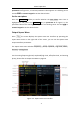


Table Of Contents
- 1.General Safety Requirement
- 2.Safety Terms and Symbols
- 3.Quick start
- 4.Panel Operation
- Channel Setting
- Waveform Setting
- Output the modulated waves
- Hexadecimal frequency shift keying (3FSK)
- Quaternary frequency shift keying (4FSK)
- Binary phase shift keying (BPSK)
- Oscillating keying (OSK)
- Output the sweep frequency (Sweep)
- Output the burst (Burst)
- Counter
- Utility function setting
- Edit the Arbitrary Wave (Edit)
- File system (Store)
- Save/recall instrument settings (Preset)
- Use build-in help (Help)
- 5.Communicate with PC
- 6.Troubleshooting
- 7.Specification
- 8.Appendix

3
.
Quick start
7
User Interface
Figure 3- 3 User Interface
1
Display channel name and channel status
2
Current waveform or current mode
3
Trigger source.
Internal: internal modulation or internal trigger source
External: external modulation or external trigger source
Manual: manual trigger source
4
Load, High Z indicates high resistance
5
This icon is lit when the network is connected through the LAN
interface.
6
This icon is lit when connected to the USB Host via the USB DEVICE
interface.
7
When the instrument detects the USB flash drive, the icon lights.
8
Current menu name
9
Current waveform or mode setting menu
10
Frequency meter brief information, displays the frequency value,
period and the duty value
11
Display a schematic of the current waveform
12
Display the current starting phase
13
Offset / low level, depending on the right highlighted menu item
14
Amplitude / high level, depending on the right highlighted menu item