
Instructions


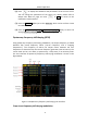


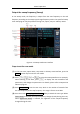


Table Of Contents
- 1.General Safety Requirement
- 2.Safety Terms and Symbols
- 3.Quick start
- 4.Panel Operation
- Channel Setting
- Waveform Setting
- Output the modulated waves
- Hexadecimal frequency shift keying (3FSK)
- Quaternary frequency shift keying (4FSK)
- Binary phase shift keying (BPSK)
- Oscillating keying (OSK)
- Output the sweep frequency (Sweep)
- Output the burst (Burst)
- Counter
- Utility function setting
- Edit the Arbitrary Wave (Edit)
- File system (Store)
- Save/recall instrument settings (Preset)
- Use build-in help (Help)
- 5.Communicate with PC
- 6.Troubleshooting
- 7.Specification
- 8.Appendix

4
.
Panel Operation
41
Steps to set frequency shift keying modulation
(1) After pressing the Mod function key, press the modulation type soft key, use
the knob to select the modulation type as BPSK, and press the ENTER key.
The carrier waveform can be selected as needed. The following is a sine wave.
(2) Press to display the waveform and parameters of the current carrier.
You can change the parameters of the carrier. For details, please refer to
Output Sine Wave on page 10. Press or Mod to return to the
modulation mode interface.
(3) Press Code Rate to set the code rate. The range is from 2 mHz to 1 MHz.
(4) Press Phase Deviation to select the phase deviation. The range is from 0° to
360°.
(5) Press Data Source to select the setting data source, including (01 code, 10
code, PN15 code, PN21 code).
Oscillating keying (OSK)
The output modulation waveform consists of a carrier wave and a modulated wave.
The carrier can only be a sine wave. In phase modulation, the phase of the carrier
varies with the keying frequency of the modulated waveform. The user interface for
the oscillating keying modulation is shown below.
Figure 4- 21 Oscillating keying user interface