
Instructions


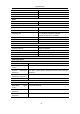

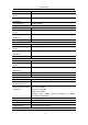


Table Of Contents
- 1.General Safety Requirement
- 2.Safety Terms and Symbols
- 3.Quick start
- 4.Panel Operation
- Channel Setting
- Waveform Setting
- Output the modulated waves
- Hexadecimal frequency shift keying (3FSK)
- Quaternary frequency shift keying (4FSK)
- Binary phase shift keying (BPSK)
- Oscillating keying (OSK)
- Output the sweep frequency (Sweep)
- Output the burst (Burst)
- Counter
- Utility function setting
- Edit the Arbitrary Wave (Edit)
- File system (Store)
- Save/recall instrument settings (Preset)
- Use build-in help (Help)
- 5.Communicate with PC
- 6.Troubleshooting
- 7.Specification
- 8.Appendix

7
.
Specification
71
Waveform
Sine wave, square wave, ramp wave, pulse wave and
arbitrary wave
Types
Count (1 to 50,000 cycles), unlimited, gated
Trigger source
Internal, external, manual
Carrier frequency
2mHz to 100MHz
Internal cycle
10 ns to 500 s (Min = Cycles * Period)
Gate source
External trigger
Counter Specification
Measurement
function
Frequency, period, positive pulse width, negative pulse
width, duty cycle
Frequency Range
Single channel: 100 mHz to 200 MHz
Frequency resolution
7 digits
Coupling method
AC, DC
Voltage range and sensitivity (non-modulated signal)
DC coupling
DC offset range
±1.5 V
100 mHz to 100 MHz
250 mVp-p - 5 Vp-p (AC+DC)
100 MHz to 200 MHz
400 mVp-p - 5 Vp-p (AC+DC)
AC coupling
1 Hz to 100 MHz
250 mVp-p - 5 Vp-p
p
100 MHz to 200 MHz
400 mVp-p - 5 Vp-p
Pulse width and duty
cycle measurement
1 Hz to 10 MHz (100 mVpp to 5 Vpp)
Input resistance
1 MΩ
Sensitivity
Can set high, medium and low three files
Trigger level range
±2.5 V
Channel coupling
1 Hz to 10 MHz (100 mVpp to 5 Vpp)
Amplitude lock, frequency lock, channel copy
Input/Output
Communication Interface
USB Host, USB Device, LAN
External modulation input
Input frequency range
DC-20 kHz
Input level range
± 1 V full scale
Input resistance
10 kΩ typical value
External trigger input
Level
TTL-compatible
Slope
Rise/fall optional
Pulse Width
>100 ns
External clock input (frequency meter input)
External clock input
(frequency meter input)
impedance
1MΩ DC coupled